
Service Manual
Page 3
...document entitled Service Handbook is also available for quick response to the user's needs. CANON PC720174017501770 REV.0 AUG. 1994 PRINTED IN JAPAN omput AU JAPON) In CHAPTER 4, "MECHANICAL SYSTEM," the copier's mechanical system is discussed as to its operation are given. All service persons are ...Information Bulletins, for troubleshooting problems in the field. INTRODUCTION This Service Manual contains the basic facts and figures about the plain paper copier PC720/740/750/770, and is compiled to serve as a handy reference for each step. CHAPTER 2 "COPYING PROCESS" deals with the...
...document entitled Service Handbook is also available for quick response to the user's needs. CANON PC720174017501770 REV.0 AUG. 1994 PRINTED IN JAPAN omput AU JAPON) In CHAPTER 4, "MECHANICAL SYSTEM," the copier's mechanical system is discussed as to its operation are given. All service persons are ...Information Bulletins, for troubleshooting problems in the field. INTRODUCTION This Service Manual contains the basic facts and figures about the plain paper copier PC720/740/750/770, and is compiled to serve as a handy reference for each step. CHAPTER 2 "COPYING PROCESS" deals with the...
Service Manual
Page 5
... 1-8 CHAPTER 2 COPYING PROCESS I. EXPOSURE SYSTEM 3-11 VII. SELF DIAGNOSIS 3-71 V. EXTERNALS 4-1 V. SPECIFICATIONS 1-1 III. FEATURES II. UNPACKING AND INSTALLATION 5-1 III. PICK-UP/FEEDING SYSTEM 3-36 VIII. CANON PC7201740,11501170 REV.O AUG. 1994 PRINTED IN JAPAN (IMPRIME AU JAPON) IMAGE FORMATION 2-1 II. CHARGING, DEVELOPING, II. DRIVE SYSTEM 4-5 AND CLEANING SYSTEMS 4-28 III. RELOCATING...
... 1-8 CHAPTER 2 COPYING PROCESS I. EXPOSURE SYSTEM 3-11 VII. SELF DIAGNOSIS 3-71 V. EXTERNALS 4-1 V. SPECIFICATIONS 1-1 III. FEATURES II. UNPACKING AND INSTALLATION 5-1 III. PICK-UP/FEEDING SYSTEM 3-36 VIII. CANON PC7201740,11501170 REV.O AUG. 1994 PRINTED IN JAPAN (IMPRIME AU JAPON) IMAGE FORMATION 2-1 II. CHARGING, DEVELOPING, II. DRIVE SYSTEM 4-5 AND CLEANING SYSTEMS 4-28 III. RELOCATING...
Service Manual
Page 9
... • The black toner cartridge may be selected. 2. Extra touches to make jam removal easy. using overlay mode, copies may be used (manual). 6. CANON PC7201740/7501770 REV.0 AUG.1994 PRINTED IN JAPAN fMPRIME AU JAPAN) 1 - 1 I. Integrated cartridge for the environment. • The use of sizes between...may be replaced with zooming. • In addition to business card may be given an extra finish. 7. Separate top unit. • The copier's top unit may simply replace the cartridge and perform simple cleaning work to 1/000 of ozone; average of 0.01 ppm or less, maximum of ...
... • The black toner cartridge may be selected. 2. Extra touches to make jam removal easy. using overlay mode, copies may be used (manual). 6. CANON PC7201740/7501770 REV.0 AUG.1994 PRINTED IN JAPAN fMPRIME AU JAPAN) 1 - 1 I. Integrated cartridge for the environment. • The use of sizes between...may be replaced with zooming. • In addition to business card may be given an extra finish. 7. Separate top unit. • The copier's top unit may simply replace the cartridge and perform simple cleaning work to 1/000 of ozone; average of 0.01 ppm or less, maximum of ...
Service Manual
Page 19
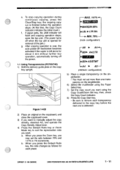
...Paper Select key. 7) Set the copy count you want using the Copy Count/Zoom Set key; CANON PC72017407501770 REV.0 AUG.1994 PRINTED IN JAPAN (IMPRIME AU JAPON) 1 - 11 open the top ...alone for about 5 min without further key operation, automatically turning off mechanism becomes activated if the copier is finished before the next one transparency on the singlefeeder. • You must not set the ...want . After copying operation is over, the auto power-off the power. 1.1 Using Transparencies (PC720/740) 1) Shift the delivery guide plate on the copyboard, and close the copyboard cover. 3) ...
...Paper Select key. 7) Set the copy count you want using the Copy Count/Zoom Set key; CANON PC72017407501770 REV.0 AUG.1994 PRINTED IN JAPAN (IMPRIME AU JAPON) 1 - 11 open the top ...alone for about 5 min without further key operation, automatically turning off mechanism becomes activated if the copier is finished before the next one transparency on the singlefeeder. • You must not set the ...want . After copying operation is over, the auto power-off the power. 1.1 Using Transparencies (PC720/740) 1) Shift the delivery guide plate on the copyboard, and close the copyboard cover. 3) ...

Service Manual
Page 23
...is copy paper. Figure 1-410 4) Pull out any . GENERAL DESCRIPTIONNM C. To remove, pull the paper slowly out of copies. If there is a jam. CANON PC720/T401759/770 REV.O AUG.1994 PRINTEDIN JAPANRout AU JAPONI 1 - 15 Removing Jams The Jam indicator flashes to tear it has torn. 1) Check the multifeeder for... a jam. C) Make sure that the cassette is properly set in the cassette, go off, and the copier will make the remaining number of the multifeeder. 2) Open the right cover, and check if there is out of paper from inside the machine. 0 ...
...is copy paper. Figure 1-410 4) Pull out any . GENERAL DESCRIPTIONNM C. To remove, pull the paper slowly out of copies. If there is a jam. CANON PC720/T401759/770 REV.O AUG.1994 PRINTEDIN JAPANRout AU JAPONI 1 - 15 Removing Jams The Jam indicator flashes to tear it has torn. 1) Check the multifeeder for... a jam. C) Make sure that the cassette is properly set in the cassette, go off, and the copier will make the remaining number of the multifeeder. 2) Open the right cover, and check if there is out of paper from inside the machine. 0 ...
Service Manual
Page 24
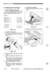
hod of the copier. 0 7I ,sue 0 Figure 1-415 Figure 1-413 2) Set the cartridge in Figure 1-410. 2. see Figure 1-409. It ;e read this ME 'ith its tun 1. Replacing the Cartridge 1) Shift up the open/close lever to the instructions under "2. CANON PC720840r/501770 REV.OAUG.1994 PRINTEDIN JAPAN0MPRIMEAU ...CANONINC. If the copy image has returned to normal, • Advise the user that, although he/she may continue to run out of .lre copier, its capabili• ng this manua ACAUTIO - : In this manii' procedure AGES with this Ft if, personal in Figure 1-412 Go through ...
hod of the copier. 0 7I ,sue 0 Figure 1-415 Figure 1-413 2) Set the cartridge in Figure 1-410. 2. see Figure 1-409. It ;e read this ME 'ith its tun 1. Replacing the Cartridge 1) Shift up the open/close lever to the instructions under "2. CANON PC720840r/501770 REV.OAUG.1994 PRINTEDIN JAPAN0MPRIMEAU ...CANONINC. If the copy image has returned to normal, • Advise the user that, although he/she may continue to run out of .lre copier, its capabili• ng this manua ACAUTIO - : In this manii' procedure AGES with this Ft if, personal in Figure 1-412 Go through ...
Service Manual
Page 25
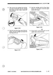
Figure 1-418 6) Press down on the mark on the copier's top to close the body. Figure 1-417 Figure 1-419 COPYRIGHT © 1994 CANON INC. then, rotate it about 50 cm). GENERAL DESCRIPTION 3) Take out the new cartridge from its bag, and hold it straight out toward the front (... the cartridge with the Open label facing up, and insert it into the copier slowly until it stops. 0 7// Figure 1-416 4) Peel the end of the Open seal of the cartridge, and pull it horizontally with the warning label facing up; CANON PCT20/7401150M0 RE© AUG.1994 PRINTEDIN JAPAN twat AUJAPON) 1 - 17...
Figure 1-418 6) Press down on the mark on the copier's top to close the body. Figure 1-417 Figure 1-419 COPYRIGHT © 1994 CANON INC. then, rotate it about 50 cm). GENERAL DESCRIPTION 3) Take out the new cartridge from its bag, and hold it straight out toward the front (... the cartridge with the Open label facing up, and insert it into the copier slowly until it stops. 0 7// Figure 1-416 4) Peel the end of the Open seal of the cartridge, and pull it horizontally with the warning label facing up; CANON PCT20/7401150M0 RE© AUG.1994 PRINTEDIN JAPAN twat AUJAPON) 1 - 17...
Service Manual
Page 31
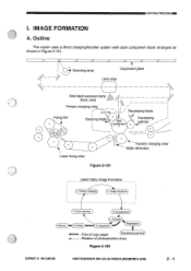
...) Delivery 6. Transfer 5. IMAGE FORMATION A. Separation Registration : Flow of copy paper (Cassette/manual feed) : Rotation of photosensitive drum Figure 2-102 COPYRIGHT © t994 CANON INC. COPYING PROCESS MI I. Outline The copier uses a direct charging/transfer system with each component block arranged as shown in Figure 2-101. /7 7/ 7/ 7/ 7/ + /7 /7 Z Scanning lamp Copyboard glass Lens array Side...
...) Delivery 6. Transfer 5. IMAGE FORMATION A. Separation Registration : Flow of copy paper (Cassette/manual feed) : Rotation of photosensitive drum Figure 2-102 COPYRIGHT © t994 CANON INC. COPYING PROCESS MI I. Outline The copier uses a direct charging/transfer system with each component block arranged as shown in Figure 2-101. /7 7/ 7/ 7/ 7/ + /7 /7 Z Scanning lamp Copyboard glass Lens array Side...
Service Manual
Page 32
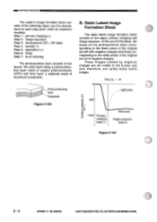
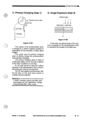
CANON PC7201140750= REV.O AUG.1994 PRINTED IN JAPAN (IMPRIME AU JAPON) These images created by negative charges are not visible to the white areas of the ... the following steps; Time (t) 0 Light area -500 Surface potential (V) -.r------ -1000 Primary charging (step 1) Dark area Image exposure (step 2) Figure 2-104 2 - 2 COPYRIGHT 1994 CANON INC. INN COPYING PROCESS The copier's image formation block consists of tow steps: primary charging and image exposure. At the end of this block, the areas on the photosensitive...
CANON PC7201140750= REV.O AUG.1994 PRINTED IN JAPAN (IMPRIME AU JAPON) These images created by negative charges are not visible to the white areas of the ... the following steps; Time (t) 0 Light area -500 Surface potential (V) -.r------ -1000 Primary charging (step 1) Dark area Image exposure (step 2) Figure 2-104 2 - 2 COPYRIGHT 1994 CANON INC. INN COPYING PROCESS The copier's image formation block consists of tow steps: primary charging and image exposure. At the end of this block, the areas on the photosensitive...
Service Manual
Page 33
...copier uses its primary charging roller to maintain primary potential. The primary charging roller is charged to a uniform negative potential in the light area. Reference: A direct charging system provides such advantages as low application voltage and generates little, if any, ozone. COPYRIGHT © 1994 CANON ... The DC bias applied simultaneously with the AC bias, on the other hand, serves to directly charge the photosensitive drum (primary charging). CANON PC720/740/150M0 REV.O AUG.1994 PRINTED IN JAPAN pmplatt AU JAPON) 2 - 3 Figure 2-106 In this step, the optical image of...
...copier uses its primary charging roller to maintain primary potential. The primary charging roller is charged to a uniform negative potential in the light area. Reference: A direct charging system provides such advantages as low application voltage and generates little, if any, ozone. COPYRIGHT © 1994 CANON ... The DC bias applied simultaneously with the AC bias, on the other hand, serves to directly charge the photosensitive drum (primary charging). CANON PC720/740/150M0 REV.O AUG.1994 PRINTED IN JAPAN pmplatt AU JAPON) 2 - 3 Figure 2-106 In this step, the optical image of...
Service Manual
Page 34
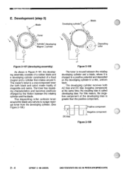
.../0 REV.O AUG.1994 PRINTED IN JAPAN (IMPRIME AU JAPON) DC bias Positive component Negative component Figure 2-109 2 - 4 COPYRIGHT © 1994 CANON INC. The copier's toner is called developing bias. For this reason, the negative component of the developing bias is charged to a positive potential and deposited on the developing ...
.../0 REV.O AUG.1994 PRINTED IN JAPAN (IMPRIME AU JAPON) DC bias Positive component Negative component Figure 2-109 2 - 4 COPYRIGHT © 1994 CANON INC. The copier's toner is called developing bias. For this reason, the negative component of the developing bias is charged to a positive potential and deposited on the developing ...

Service Manual
Page 35
... paper is retained by the photosensitive drum surface potential and the developing bias (negative component). ging. The copier uses a roller transfer system, which has the following advantages when compared with an increased tendency toward fog- F. CANON PC7201740/750,710 REV.0 AUG.1994 PRINTED IN JAPAN ompnimt AU JAPON) 2 - 5 A DC bias affects copy...
... paper is retained by the photosensitive drum surface potential and the developing bias (negative component). ging. The copier uses a roller transfer system, which has the following advantages when compared with an increased tendency toward fog- F. CANON PC7201740/750,710 REV.0 AUG.1994 PRINTED IN JAPAN ompnimt AU JAPON) 2 - 5 A DC bias affects copy...
Service Manual
Page 36
...the heater is controlled to the film-this design eliminates the need for warm-up time. CANON PC720,740/750i770 REY.0 AUG.1994 PRINTEDIN JAPAN DIARIME AU JAPON) To prevent such a problem, the copier applies a positive voltage to the separation static eliminator to the paper while the copy paper... moves through the fixing film and the pressure roller. The fixing film has a seamless construction and is why the copier's fixing assembly does not have a cleaning mechanism. The fixing heater is separated from the photosensitive drum using the rigidity of the fixing ...
...the heater is controlled to the film-this design eliminates the need for warm-up time. CANON PC720,740/750i770 REY.0 AUG.1994 PRINTEDIN JAPAN DIARIME AU JAPON) To prevent such a problem, the copier applies a positive voltage to the separation static eliminator to the paper while the copy paper... moves through the fixing film and the pressure roller. The fixing film has a seamless construction and is why the copier's fixing assembly does not have a cleaning mechanism. The fixing heater is separated from the photosensitive drum using the rigidity of the fixing ...
Service Manual
Page 42
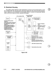
... Delivery paper detection • Film displacement detection • Cartridge color detection • Cassette detection • Singlefeeder pick-up detection (PC720/740) Q101 CPU +5V +24V 4 Composite power supply PCB Q90O H Scanning lamp Fixing heater CPU Highvoltage circuit Contact PCB •.../lens drive motor Figure 3-102 3- 2 COPYRIGHT © 1994 CANONINC. CANON PC72017050/770 REV.O AUG.1994 PRINTEDIN JAPANRout AU JAPON) =OPERATIONS AND TIMING B. Electrical Circuitry The copier's major electrical control mechanisms are driven by the microprocessor on the DC controller...
... Delivery paper detection • Film displacement detection • Cartridge color detection • Cassette detection • Singlefeeder pick-up detection (PC720/740) Q101 CPU +5V +24V 4 Composite power supply PCB Q90O H Scanning lamp Fixing heater CPU Highvoltage circuit Contact PCB •.../lens drive motor Figure 3-102 3- 2 COPYRIGHT © 1994 CANONINC. CANON PC72017050/770 REV.O AUG.1994 PRINTEDIN JAPANRout AU JAPON) =OPERATIONS AND TIMING B. Electrical Circuitry The copier's major electrical control mechanisms are driven by the microprocessor on the DC controller...

Service Manual
Page 57
... DC controller PCB fluorescent lamp driver High-voltage circuit 4 O900 Microprocessor Composite power supply PCB Figure 3-301 COPYRIGHT 1994 CANON INC. CANON PC720114017501770 RE0.0 AUG.1994 PRINTED IN JAPAN (IMPRIME AU JAPAN) 3 - 17 OPERATIONS AND TIMINGISM III. Copyboard glass... \ \Scanning lamp Intensity sensor AE sensor Lens Blank exposure lamp Primary charging rollerj; Outline The copier's image formation system performs the following ...
... DC controller PCB fluorescent lamp driver High-voltage circuit 4 O900 Microprocessor Composite power supply PCB Figure 3-301 COPYRIGHT 1994 CANON INC. CANON PC720114017501770 RE0.0 AUG.1994 PRINTED IN JAPAN (IMPRIME AU JAPAN) 3 - 17 OPERATIONS AND TIMINGISM III. Copyboard glass... \ \Scanning lamp Intensity sensor AE sensor Lens Blank exposure lamp Primary charging rollerj; Outline The copier's image formation system performs the following ...

Service Manual
Page 59
...ambient temperature is a fluorescent lamp. OPERATIONS AND TIMING= C. In consideration of these characteristics of the fluorescent lamp has stabilized. The copier does not start copying operation until the intensity of the scanning lamp. Pre-heat transformer (T401) Pre-heat voltage control circuit VR101... lamp driver Q900 FLON* icroprocessor Intensity signal FLPRHT DC controller PCB Composite power supply PCB Figure 3-304 COPYRIGHT © 1994 CANON INC. Outline Figure 3-304 shows the circuit that it is equipped with an intensity sensor so that the originals may be ...
...ambient temperature is a fluorescent lamp. OPERATIONS AND TIMING= C. In consideration of these characteristics of the fluorescent lamp has stabilized. The copier does not start copying operation until the intensity of the scanning lamp. Pre-heat transformer (T401) Pre-heat voltage control circuit VR101... lamp driver Q900 FLON* icroprocessor Intensity signal FLPRHT DC controller PCB Composite power supply PCB Figure 3-304 COPYRIGHT © 1994 CANON INC. Outline Figure 3-304 shows the circuit that it is equipped with an intensity sensor so that the originals may be ...
Service Manual
Page 63
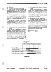
CANON PC720/740/750/770 REV.O AUG.1994 PRINTED IN JAPAN omput AU JAPON) 3 - 23 MWAIOPERATIONS AND ...) Primary charging roller DC bias Primary charging roller AC bias P e-heatn -400V -625V -400V Figure 3-307 COPYRIGHT O 1994 CANON INC. b. Turning On and Off the DC/AC Bias When the Copy Start key is controlled to a specific voltage by varying...the DC bias voltage to whether or not copy images are being formed. Switching the DC Bias Voltage Level The copier switches the level of voltage taken. Controlling the DC Bias to a Specific Voltage The DC bias is pressed, the...
CANON PC720/740/750/770 REV.O AUG.1994 PRINTED IN JAPAN omput AU JAPON) 3 - 23 MWAIOPERATIONS AND ...) Primary charging roller DC bias Primary charging roller AC bias P e-heatn -400V -625V -400V Figure 3-307 COPYRIGHT O 1994 CANON INC. b. Turning On and Off the DC/AC Bias When the Copy Start key is controlled to a specific voltage by varying...the DC bias voltage to whether or not copy images are being formed. Switching the DC Bias Voltage Level The copier switches the level of voltage taken. Controlling the DC Bias to a Specific Voltage The DC bias is pressed, the...

Service Manual
Page 66
CANON PC72017401750/770 REV.O AUG.19M PRINTEDIN JAPAN pout AU JAPON) Controlling the Voltage Level of the DC Bias to Suit the Copy Density Setting The copier varies the DC bias control signal (DCBPWM) according to the settings shown below to vary the DC component voltage, thereby controlling ...(SW101) on the DC controller PCB may be set to correct foggy images caused by changes in automatic mode. 3 - 26 COPYRIGHT @ 1994 CANON INC. The density correction switch (SW101) functions when the density is adjusted in manual mode or during automatic density adjustment mode. 0 .miera cts ...
CANON PC72017401750/770 REV.O AUG.19M PRINTEDIN JAPAN pout AU JAPON) Controlling the Voltage Level of the DC Bias to Suit the Copy Density Setting The copier varies the DC bias control signal (DCBPWM) according to the settings shown below to vary the DC component voltage, thereby controlling ...(SW101) on the DC controller PCB may be set to correct foggy images caused by changes in automatic mode. 3 - 26 COPYRIGHT @ 1994 CANON INC. The density correction switch (SW101) functions when the density is adjusted in manual mode or during automatic density adjustment mode. 0 .miera cts ...
Service Manual
Page 68
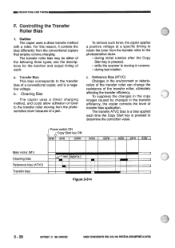
... (ATVC) Transfer bias sec (approx.) U Figure 3-314 3 - 28 COPYRIGHT © 1994 CANON INC. Reference Bias (ATVC) Changes in the transfer efficiency, the copier corrects the level of a jam. b. CANON PC720/74000770 REV.O AUG.1994 PRINTED IN JAPAN pmpFeat AU JAPAN) For this reason, it controls the ... initial rotation after the Copy Start key is pressed. • while the scanner is a negative voltage. To remove such toner, the copier applies a positive voltage at a specific timing to return the toner from the transfer roller to determine the correction value. The transfer ATVC ...
... (ATVC) Transfer bias sec (approx.) U Figure 3-314 3 - 28 COPYRIGHT © 1994 CANON INC. Reference Bias (ATVC) Changes in the transfer efficiency, the copier corrects the level of a jam. b. CANON PC720/74000770 REV.O AUG.1994 PRINTED IN JAPAN pmpFeat AU JAPAN) For this reason, it controls the ... initial rotation after the Copy Start key is pressed. • while the scanner is a negative voltage. To remove such toner, the copier applies a positive voltage at a specific timing to return the toner from the transfer roller to determine the correction value. The transfer ATVC ...

Service Manual
Page 70
...composite power supply PCB. The current detection circuit detects the current flowing through the transformer/rectifier circuit. 3 - 30 COPYRIGHT © 1994 CANON CANON PC72011401150= RBA AUG.1994 PRINTED IN JAPAN (IMPRNE AU JAPONI The microprocessor on the composite power supply PCB, on the other hand, ...compensate for the changes in the transfer efficiency caused by changes in any of copy paper. After Starting Copying The copier automatically corrects the application voltage during initial rotation after starting copying (ATVC) • after a press on signal and, at all ...
...composite power supply PCB. The current detection circuit detects the current flowing through the transformer/rectifier circuit. 3 - 30 COPYRIGHT © 1994 CANON CANON PC72011401150= RBA AUG.1994 PRINTED IN JAPAN (IMPRNE AU JAPONI The microprocessor on the composite power supply PCB, on the other hand, ...compensate for the changes in the transfer efficiency caused by changes in any of copy paper. After Starting Copying The copier automatically corrects the application voltage during initial rotation after starting copying (ATVC) • after a press on signal and, at all ...


