Service Manual
Page 7
... 1.1.2.3 Handling of the Laser Assembly ...1- 6 1.1.2.4 Safety of the Toner ...1- 6 1.1.2.5 Fire Attention...1- 6 1.1.2.6 Points no Note when Replacing / Disposing the Lithium Battery 1- 7 1.1.3 Product Specifications ...1- 7 1.1.3.1 Host Machine Specifications...1- 7 1.1.3.2 ADF Specifications...1- 8 1.1.3.3 FAX Specifications...1- 8 1.1.4 Function List ...1- 9 1.1.4.1 Scanning Range ...1- 9 1.1.4.2 Recording Range (Copy) ...1- 10 1.1.4.3 Recording Range (Reception) ...1- 10 1.1.4.4 Recording Range (Printer) ...1- 11 1.1.4.5 Operation Environment of the Printer Driver...1- 11 1.1.4.6 Network...
... 1.1.2.3 Handling of the Laser Assembly ...1- 6 1.1.2.4 Safety of the Toner ...1- 6 1.1.2.5 Fire Attention...1- 6 1.1.2.6 Points no Note when Replacing / Disposing the Lithium Battery 1- 7 1.1.3 Product Specifications ...1- 7 1.1.3.1 Host Machine Specifications...1- 7 1.1.3.2 ADF Specifications...1- 8 1.1.3.3 FAX Specifications...1- 8 1.1.4 Function List ...1- 9 1.1.4.1 Scanning Range ...1- 9 1.1.4.2 Recording Range (Copy) ...1- 10 1.1.4.3 Recording Range (Reception) ...1- 10 1.1.4.4 Recording Range (Printer) ...1- 11 1.1.4.5 Operation Environment of the Printer Driver...1- 11 1.1.4.6 Network...
Service Manual
Page 17
......1-6 1.1.2.3 Handling of the Laser Assembly...1-6 1.1.2.4 Safety of the Toner...1-6 1.1.2.5 Fire Attention ...1-6 1.1.2.6 Points no Note when Replacing / Disposing the Lithium Battery ...1-7 1.1.3 Product Specifications ...1-7 1.1.3.1 Host Machine Specifications...1-7 1.1.3.2 ADF Specifications ...1-8 1.1.3.3 FAX Specifications ...1-8 1.1.4 Function List ...1-9 1.1.4.1 Scanning Range...1-9 1.1.4.2 Recording Range (Copy)...1-10 1.1.4.3 Recording Range (Reception) ...1-10 1.1.4.4 Recording Range (Printer) ...1-11 1.1.4.5 Operation Environment of the Printer Driver ...1-11 1.1.4.6 Network...
......1-6 1.1.2.3 Handling of the Laser Assembly...1-6 1.1.2.4 Safety of the Toner...1-6 1.1.2.5 Fire Attention ...1-6 1.1.2.6 Points no Note when Replacing / Disposing the Lithium Battery ...1-7 1.1.3 Product Specifications ...1-7 1.1.3.1 Host Machine Specifications...1-7 1.1.3.2 ADF Specifications ...1-8 1.1.3.3 FAX Specifications ...1-8 1.1.4 Function List ...1-9 1.1.4.1 Scanning Range...1-9 1.1.4.2 Recording Range (Copy)...1-10 1.1.4.3 Recording Range (Reception) ...1-10 1.1.4.4 Recording Range (Printer) ...1-11 1.1.4.5 Operation Environment of the Printer Driver ...1-11 1.1.4.6 Network...

Service Manual
Page 35
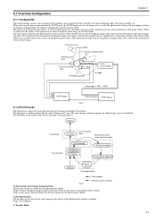
... this host machine are mainly composed of the 7 blocks: System Control System, Scanning Control System, Printer Control System, Laser Scanner System, Image Formation System, Fixing System, Pickup/Feeding System. System Control System Scanning Control System Laser / Scanner System Printer Control System Image Formation System Fixing System Pickup / Feeding System F-2-1 2.2 Basic Sequence 2.2.1 Basic Operation Sequence...
... this host machine are mainly composed of the 7 blocks: System Control System, Scanning Control System, Printer Control System, Laser Scanner System, Image Formation System, Fixing System, Pickup/Feeding System. System Control System Scanning Control System Laser / Scanner System Printer Control System Image Formation System Fixing System Pickup / Feeding System F-2-1 2.2 Basic Sequence 2.2.1 Basic Operation Sequence...
Service Manual
Page 69
...transfer charging roller. Fixing Drum cleaning block Electrostatic latent image formation block 7. The latent image formed on papers by the printer. Primary charging 2. When receiving the print command from the SCNT board, the DCNT board activates the main motor to visualize ...Step 3: Development 3) Transfer block 6-1 Laser beam exposure Pick-up 3. Delivery Fixing block 6. Drum cleaning Transfer block 5. 6.1 Overview/Configuration Chapter 6 6.1.1 Configuration 0016-1839 The...
...transfer charging roller. Fixing Drum cleaning block Electrostatic latent image formation block 7. The latent image formed on papers by the printer. Primary charging 2. When receiving the print command from the SCNT board, the DCNT board activates the main motor to visualize ...Step 3: Development 3) Transfer block 6-1 Laser beam exposure Pick-up 3. Delivery Fixing block 6. Drum cleaning Transfer block 5. 6.1 Overview/Configuration Chapter 6 6.1.1 Configuration 0016-1839 The...

Service Manual
Page 82
... 7.5.1.1 Preparation for Removing Separation Pad 0016-5042 1) Remove the front cover. 2) Remove the right cover. 3) Remove the left cover. 4) Remove the DCNT board. 5) Remove the laser scanner unit. 7.5.1.2 Removing Main Motor 1) Remove the 2 screws [1], and remove the main motor [2]. Do not touch the roller with bare hands. 0016-5040 0016-5041... Separation Pad 0016-5044 1) Remove the 2 screws [1], and remove the separation pad [2]. F-7-8 F-7-6 7.5.3 Pickup Roller 7.5.3.1 Removing Pickup Roller 0016-5045 1) Open the control panel [1]. 2) Open the printer cover [2].
... 7.5.1.1 Preparation for Removing Separation Pad 0016-5042 1) Remove the front cover. 2) Remove the right cover. 3) Remove the left cover. 4) Remove the DCNT board. 5) Remove the laser scanner unit. 7.5.1.2 Removing Main Motor 1) Remove the 2 screws [1], and remove the main motor [2]. Do not touch the roller with bare hands. 0016-5040 0016-5041... Separation Pad 0016-5044 1) Remove the 2 screws [1], and remove the separation pad [2]. F-7-8 F-7-6 7.5.3 Pickup Roller 7.5.3.1 Removing Pickup Roller 0016-5045 1) Open the control panel [1]. 2) Open the printer cover [2].
Service Manual
Page 131
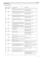
... DC controller PCB. Replace the main motor. - Replace the DC controller PCB. Replace the image processor PCB. Erroneous communication with the printer at startup). - Replace the image processor PCB. Check the connector of the fixing film unit. - Low temperature during startup control. ...Replace the DC controller PCB. - Check the connector of the fixing film unit. - Replace the laser scanner unit. - PCL ROM write/read error The write/read of the printer (Check whether initialization is faulty. inside of the fixing film unit. - Replace the DC controller ...
... DC controller PCB. Replace the main motor. - Replace the DC controller PCB. Replace the image processor PCB. Erroneous communication with the printer at startup). - Replace the image processor PCB. Check the connector of the fixing film unit. - Low temperature during startup control. ...Replace the DC controller PCB. - Check the connector of the fixing film unit. - Replace the laser scanner unit. - PCL ROM write/read error The write/read of the printer (Check whether initialization is faulty. inside of the fixing film unit. - Replace the DC controller ...


