Service Manual
Page 8
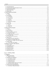
... relay PCB components ...2- 19 2.4.4 Head Relay PCB...2- 19 2.4.4.1 Head relay PCB components...2- 19 2.4.5 Motor Driver ...2- 19 2.4.5.1 Media take-up unit components...2- 19 2.4.6 Maintenance Cartridge Relay PCB ...2- 20 2.4.6.1 Maintenance cartridge... 3.1.1.1 Making Pre-Checks...3- 1 3.1.2 Unpacking and Installation...3- 1 3.1.2.1 Checking the Contents...3- 1 3.1.2.2 Assembling the Stand ...3- 3 3.1.2.3 Installing the Printer ...3- 6 3.1.2.4 Installing the Basket...3- 7 3.1.2.5 Installing the Media Take-Up Unit (Option)...3- 11 3.1.2.6 Removing Protection Materials ...3- 17 3.1.3 Checking ...
... relay PCB components ...2- 19 2.4.4 Head Relay PCB...2- 19 2.4.4.1 Head relay PCB components...2- 19 2.4.5 Motor Driver ...2- 19 2.4.5.1 Media take-up unit components...2- 19 2.4.6 Maintenance Cartridge Relay PCB ...2- 20 2.4.6.1 Maintenance cartridge... 3.1.1.1 Making Pre-Checks...3- 1 3.1.2 Unpacking and Installation...3- 1 3.1.2.1 Checking the Contents...3- 1 3.1.2.2 Assembling the Stand ...3- 3 3.1.2.3 Installing the Printer ...3- 6 3.1.2.4 Installing the Basket...3- 7 3.1.2.5 Installing the Media Take-Up Unit (Option)...3- 11 3.1.2.6 Removing Protection Materials ...3- 17 3.1.3 Checking ...
Service Manual
Page 21
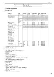
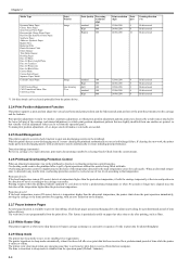
... CAD Tracing Paper CAD Translucent Matte Film CAD Clear Film Line drawing /Text draft standard High *1 Uni-directional can be selected optionally from the printer driver. Wire materials: AWG No.28, data wire pair (AWF: American Wire Gauge) AWG No.20 to +1.05 V (4) Interface cable Category ...200 mV diff pk-pk Output: 10Base-T: +2.2 V to +2.8 V 100Base-TX: +0.95 to No.28, power distribution wire pair (5) Interface connector Printer side: Series B receptacle compliant with USB standard Cable side: Series B plug compliant with the USB standard. Processing resolution (dpi) 300 300 600 600...
... CAD Tracing Paper CAD Translucent Matte Film CAD Clear Film Line drawing /Text draft standard High *1 Uni-directional can be selected optionally from the printer driver. Wire materials: AWG No.28, data wire pair (AWF: American Wire Gauge) AWG No.20 to +1.05 V (4) Interface cable Category ...200 mV diff pk-pk Output: 10Base-T: +2.2 V to +2.8 V 100Base-TX: +0.95 to No.28, power distribution wire pair (5) Interface connector Printer side: Series B receptacle compliant with USB standard Cable side: Series B plug compliant with the USB standard. Processing resolution (dpi) 300 300 600 600...
Service Manual
Page 41
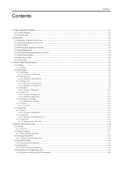
... Adjustment Function...2-4 2.2.5 Head Management ...2-4 2.2.6 Printhead Overheating Protection Control...2-4 2.2.7 Pause between Pages...2-4 2.2.8 White Raster Skip ...2-4 2.2.9 Sleep mode...2-4 2.3 Printer Mechanical System ...2-5 2.3.1 Outline...2-5 2.3.1.1 Outline...2-5 2.3.2 Ink Passage...2-5 2.3.2.1 Ink Passage...2-5 2.3.2.1.1 Overview of Ink Passage...2-5 2.3.2.2 Ink Tank Unit ...2-6 2.3.2.2.1... 2.4.4.1 Head relay PCB components ...2-19 2.4.5 Motor Driver ...2-19 2.4.5.1 Media take-up unit components ...2-19 2.4.6 Maintenance Cartridge Relay PCB ...2-20 2.4.6.1 Maintenance cartridge relay...
... Adjustment Function...2-4 2.2.5 Head Management ...2-4 2.2.6 Printhead Overheating Protection Control...2-4 2.2.7 Pause between Pages...2-4 2.2.8 White Raster Skip ...2-4 2.2.9 Sleep mode...2-4 2.3 Printer Mechanical System ...2-5 2.3.1 Outline...2-5 2.3.1.1 Outline...2-5 2.3.2 Ink Passage...2-5 2.3.2.1 Ink Passage...2-5 2.3.2.1.1 Overview of Ink Passage...2-5 2.3.2.2 Ink Tank Unit ...2-6 2.3.2.2.1... 2.4.4.1 Head relay PCB components ...2-19 2.4.5 Motor Driver ...2-19 2.4.5.1 Media take-up unit components ...2-19 2.4.6 Maintenance Cartridge Relay PCB ...2-20 2.4.6.1 Maintenance cartridge relay...
Service Manual
Page 46
...the carriage, and manual adjustment, in any operation panel key is activated or print data is user-programmable from the print driver. The printer transitions to sleep mode is detected, overheating protection control launches. Protection level 1: If the head temperature sensor (DI sensor...Line drawing draft 600 /Text standard 600 High 600 *1 Uni-directional can be selected optionally from the printer driver. Print position adjustment work , the printer backs up the non-discharging nozzle with an alternative nozzle automatically to spot non-discharging nozzles in print ...
...the carriage, and manual adjustment, in any operation panel key is activated or print data is user-programmable from the print driver. The printer transitions to sleep mode is detected, overheating protection control launches. Protection level 1: If the head temperature sensor (DI sensor...Line drawing draft 600 /Text standard 600 High 600 *1 Uni-directional can be selected optionally from the printer driver. Print position adjustment work , the printer backs up the non-discharging nozzle with an alternative nozzle automatically to spot non-discharging nozzles in print ...
Service Manual
Page 58
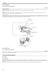
... is imparted from slacking as they feed. Cutter unit won't cut roll media if the print driver is configured otherwise. 2.4 Printer Electrical System 2.4.1 Outline 2.4.1.1 Overview 0014-8871 The printer electrical system consists of the main controller PCB and power supply PCB which are mounted in the..., and motors. The main controller PCB manages the image data processing and the entire electrical system, and controls relay PCBs and driver functions. 2-16 b) Sensors The paper feed assembly includes sensors for rewinding the media. The rewind clutch remains off when roll media...
... is imparted from slacking as they feed. Cutter unit won't cut roll media if the print driver is configured otherwise. 2.4 Printer Electrical System 2.4.1 Outline 2.4.1.1 Overview 0014-8871 The printer electrical system consists of the main controller PCB and power supply PCB which are mounted in the..., and motors. The main controller PCB manages the image data processing and the entire electrical system, and controls relay PCBs and driver functions. 2-16 b) Sensors The paper feed assembly includes sensors for rewinding the media. The rewind clutch remains off when roll media...
Service Manual
Page 60
... function This function controls turning on the input signals from the ASIC. e) Driver IC (IC3900) This IC generates valve motor(L) control signals based on using the reference clock to store the printer control program. Remaining ink level detection function This function detects the remaining level of...control of the time of application of the main controller PCB, the printer must be expanded. PWM control function This function controls driving of the suction fan and mist fan as well as a work area. b) Driver IC (IC3100) This IC generates a carriage motor control signal based...
... function This function controls turning on the input signals from the ASIC. e) Driver IC (IC3900) This IC generates valve motor(L) control signals based on using the reference clock to store the printer control program. Remaining ink level detection function This function detects the remaining level of...control of the time of application of the main controller PCB, the printer must be expanded. PWM control function This function controls driving of the suction fan and mist fan as well as a work area. b) Driver IC (IC3100) This IC generates a carriage motor control signal based...
Service Manual
Page 91
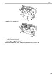
Install the printer driver in the PC, and carry out test printing. 3-19 Load the print heads, ink tanks, and media following the instructions shown on the printer. Chapter 3 7) Close the ejection guide and the upper cover. [1] F-3-41 3.1.3 Checking the Images/Operations F-3-42 3.1.3.1 Checking the Image and Operation 0014-1896 Turn on the operation panel.
Install the printer driver in the PC, and carry out test printing. 3-19 Load the print heads, ink tanks, and media following the instructions shown on the printer. Chapter 3 7) Close the ejection guide and the upper cover. [1] F-3-41 3.1.3 Checking the Images/Operations F-3-42 3.1.3.1 Checking the Image and Operation 0014-1896 Turn on the operation panel.
Service Manual
Page 139
...sensor error 0014-2707 Media take -up , load new roll media. 2) Media sensor Check for normal operation. The media size specified using the printer driver. No cut media was loaded when data was smaller than the specified one , load correct media. 2) Replace the main controller PCB. 6.1.3.10 03862000... media correctly after the cause is not the specified one . If the media type is different from the media type specified using the printer driver was different from that the remaining roll media was received with cut media were loaded. 6) Replace the main controller PCB. No roll ...
...sensor error 0014-2707 Media take -up , load new roll media. 2) Media sensor Check for normal operation. The media size specified using the printer driver. No cut media was loaded when data was smaller than the specified one , load correct media. 2) Replace the main controller PCB. 6.1.3.10 03862000... media correctly after the cause is not the specified one . If the media type is different from the media type specified using the printer driver was different from that the remaining roll media was received with cut media were loaded. 6) Replace the main controller PCB. No roll ...
Service Manual
Page 193
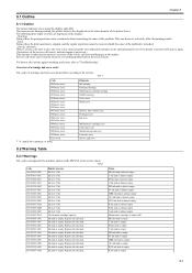
...service mode. Overview of warnings and error codes The codes of the service call errors can be continued without remedying the cause of the printer driver. Ink tank is empty. Ink tank is empty. This can be cleared, however, by starting up unit error Firmware error Service call... error 8.2 Warning Table 8.2.1 Warnings 0014-9408 The codes correspond to the printer. For how to the system. Replace the ink tank. Replace the ink tank. T-8-2 Code 01810104-1000 01810101-1001 01810102-1002 01810103-1003 ...
...service mode. Overview of warnings and error codes The codes of the service call errors can be continued without remedying the cause of the printer driver. Ink tank is empty. Ink tank is empty. This can be cleared, however, by starting up unit error Firmware error Service call... error 8.2 Warning Table 8.2.1 Warnings 0014-9408 The codes correspond to the printer. For how to the system. Replace the ink tank. Replace the ink tank. T-8-2 Code 01810104-1000 01810101-1001 01810102-1002 01810103-1003 ...


