0871LH1 Freezing Rain Sensor
Page 1
INSTRUCTION MANUAL 0871LH1 Freezing Rain Sensor November 2012 Copyright © 2007 Campbell Scientific (Canada)Corp.
INSTRUCTION MANUAL 0871LH1 Freezing Rain Sensor November 2012 Copyright © 2007 Campbell Scientific (Canada)Corp.
0871LH1 Freezing Rain Sensor
Page 4
... 1.2 Watchdog/Reset Circuit...24 1.3 Serial EEPROM...24 1.4 Probe Oscillator ...24 1.5 Heater Control ...24 1.6 Drive Coil...25 1.7 Feedback Coil ...25 1.8 Heater...25 1.9 DC Power Supply ...25 1.10 Status Output ...25 1.11 Ice Signal Output ...25 2 Qualification Capabilities ...26 3 Input/Output Specification ...27 3.1 Input/Output Pin Designations 27 TABLE OF FIGURES Figure 1 MSO Circuit Sectional View...3 Figure 2 MSO Circuit Schematic ...3 Figure 3 Ice Detector...5 Figure 4 Mounting (part number 0871LH1 MNT)...6 Figure 5 General Hook-up Diagram...
... 1.2 Watchdog/Reset Circuit...24 1.3 Serial EEPROM...24 1.4 Probe Oscillator ...24 1.5 Heater Control ...24 1.6 Drive Coil...25 1.7 Feedback Coil ...25 1.8 Heater...25 1.9 DC Power Supply ...25 1.10 Status Output ...25 1.11 Ice Signal Output ...25 2 Qualification Capabilities ...26 3 Input/Output Specification ...27 3.1 Input/Output Pin Designations 27 TABLE OF FIGURES Figure 1 MSO Circuit Sectional View...3 Figure 2 MSO Circuit Schematic ...3 Figure 3 Ice Detector...5 Figure 4 Mounting (part number 0871LH1 MNT)...6 Figure 5 General Hook-up Diagram...
0871LH1 Freezing Rain Sensor
Page 5
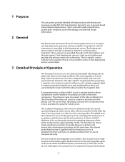
... applied until the frequency rises to a predetermined set point plus an additional delay factor to the operator that an icing condition exists so that detects the presence of icing condition. At the same time, the internal probe heater power is used to indicate to ...detailed design information. Once de-iced, the sensing probe cools within a few seconds and is used on the sensing probe. These outputs are provided through an RS-422 interface and discrete outputs. 1 Purpose 2 General This document provides detailed information about the Rosemount Aerospace model 0871LH1 Freezing ...
... applied until the frequency rises to a predetermined set point plus an additional delay factor to the operator that an icing condition exists so that detects the presence of icing condition. At the same time, the internal probe heater power is used to indicate to ...detailed design information. Once de-iced, the sensing probe cools within a few seconds and is used on the sensing probe. These outputs are provided through an RS-422 interface and discrete outputs. 1 Purpose 2 General This document provides detailed information about the Rosemount Aerospace model 0871LH1 Freezing ...
0871LH1 Freezing Rain Sensor
Page 7
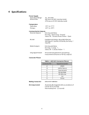
... - 0, Status Failure - 1 Icing Signal Period: 60 second activation from start of icing measurement (Discrete or RS-422 outputs) Connector Pinout Table 1. 0871LH1 Connector Pinout Connector Pin Signal Description A 24VDC B 24VDC Return C Case Ground D RS-422 High E RS-422 Low F Ice G Status Mating Connector: MS27473T10B99SN De-icing Control Automatically triggered with accumulation of 0.5mm of ice on probe Max heating time - 25 seconds 4
... - 0, Status Failure - 1 Icing Signal Period: 60 second activation from start of icing measurement (Discrete or RS-422 outputs) Connector Pinout Table 1. 0871LH1 Connector Pinout Connector Pin Signal Description A 24VDC B 24VDC Return C Case Ground D RS-422 High E RS-422 Low F Ice G Status Mating Connector: MS27473T10B99SN De-icing Control Automatically triggered with accumulation of 0.5mm of ice on probe Max heating time - 25 seconds 4
0871LH1 Freezing Rain Sensor
Page 9
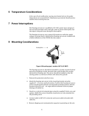
... and lock washers. Attach to DO-160C power input category Z. Remove shipping cover and protective cap prior to verify the supply voltage. The unit will remember status through a 200 ms power interruption, but the output string will cease during the interruption. Attach the freezing rain sensor to bracket with cable ties. 5. Connect cable to 0871LH1 connector and secure cable to the mounting bracket using the supplied...
... and lock washers. Attach to DO-160C power input category Z. Remove shipping cover and protective cap prior to verify the supply voltage. The unit will remember status through a 200 ms power interruption, but the output string will cease during the interruption. Attach the freezing rain sensor to bracket with cable ties. 5. Connect cable to 0871LH1 connector and secure cable to the mounting bracket using the supplied...
0871LH1 Freezing Rain Sensor
Page 10
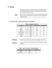
... Output Description Ice Status RS422 A RS422 B Power Reference Case GND 5V Power Shield Table 2. Power Connections to properly install the C2673 power supply. Isolate wires that are not connected as they will depend on the required communication outputs of your application. If you require the use of the RS422 output, then refer to section 9.2. Datalogger Connections Pin Colour CR3000/CR1000 F Blue C1 G Yellow C2 D White N/C E Brown N/C B Black...
... Output Description Ice Status RS422 A RS422 B Power Reference Case GND 5V Power Shield Table 2. Power Connections to properly install the C2673 power supply. Isolate wires that are not connected as they will depend on the required communication outputs of your application. If you require the use of the RS422 output, then refer to section 9.2. Datalogger Connections Pin Colour CR3000/CR1000 F Blue C1 G Yellow C2 D White N/C E Brown N/C B Black...

0871LH1 Freezing Rain Sensor
Page 11
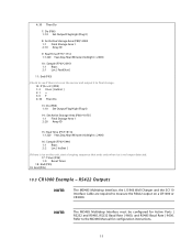
MD485 F Blue G Yellow D White E Brown B Black C Green Purple Clear N/C N/C RS485 A RS485 B N/C N/C N/C N/C Sensor - Description Ice Status RS422 A RS422 B Power Reference Case GND 5V Power Shield Table 4. CR1000/CR3000 N/C N/C N/C N/C G G G G 8 Datalogger Connections Pin Colour Sensor - Figure 5 General Hook-up Diagram 9.2 0871LH1CBL-L Wiring for configuration instructions. Refer to the MD485 Manual for RS422 Output NOTE: The MD485 Multidrop Interface, the L15966 Wall Charger and the SC110 Interface Cable are...
MD485 F Blue G Yellow D White E Brown B Black C Green Purple Clear N/C N/C RS485 A RS485 B N/C N/C N/C N/C Sensor - Description Ice Status RS422 A RS422 B Power Reference Case GND 5V Power Shield Table 4. CR1000/CR3000 N/C N/C N/C N/C G G G G 8 Datalogger Connections Pin Colour Sensor - Figure 5 General Hook-up Diagram 9.2 0871LH1CBL-L Wiring for configuration instructions. Refer to the MD485 Manual for RS422 Output NOTE: The MD485 Multidrop Interface, the L15966 Wall Charger and the SC110 Interface Cable are...
0871LH1 Freezing Rain Sensor
Page 12
... events and changes to ground. Table 6. Discrete Outputs Monitor the discrete outputs of the 0871LH1 for the datalogger to receive data from the 0871LH1, 'ports 1 & 2 must be configured as they may cause problems if shorted to the sensor status. NOTE: If the application requires the monitoring of the discrete outputs the 5Vdc connection must be made. Data tables are not connected as inputs. Table...
... events and changes to ground. Table 6. Discrete Outputs Monitor the discrete outputs of the 0871LH1 for the datalogger to receive data from the 0871LH1, 'ports 1 & 2 must be configured as they may cause problems if shorted to the sensor status. NOTE: If the application requires the monitoring of the discrete outputs the 5Vdc connection must be made. Data tables are not connected as inputs. Table...

0871LH1 Freezing Rain Sensor
Page 13
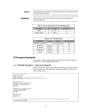
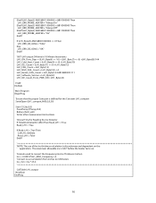
Scan (5,Sec,0,0) 'Start timer to corrdinate monitoring of the ports and store to input locations for icing and status. If yes, the sensor signals the icing event, heats the probe, and resets counter. 'If no, the sensor signals no ice and resets ...code is stored to the Sensor Status data table. 'Only fault status data is detected then store the record to monitor Control Ports 1 & 2 every 61 seconds 2: If (XF) (P89) 1: 3 X Loc [ Timer ] 2: 3 >= 3: 61 F 4: 30 Then Do 3: Set Port(s) (P20) 1: 9999 C8..C5 = nc/nc/nc/nc 2: 9988 C4..C1 = nc/nc/input/input ;Read the status of ice signal output...
Scan (5,Sec,0,0) 'Start timer to corrdinate monitoring of the ports and store to input locations for icing and status. If yes, the sensor signals the icing event, heats the probe, and resets counter. 'If no, the sensor signals no ice and resets ...code is stored to the Sensor Status data table. 'Only fault status data is detected then store the record to monitor Control Ports 1 & 2 every 61 seconds 2: If (XF) (P89) 1: 3 X Loc [ Timer ] 2: 3 >= 3: 61 F 4: 30 Then Do 3: Set Port(s) (P20) 1: 9999 C8..C5 = nc/nc/nc/nc 2: 9988 C4..C1 = nc/nc/input/input ;Read the status of ice signal output...
0871LH1 Freezing Rain Sensor
Page 14
...Manual for Active Ports | RS232 and RS485, RS232 Baud Rate | 9600, and RS485 Baud Rate | 9600. Refer to final storage. 12: If (XF) (P89) 1: 2 X Loc [ IceStat ] 2: 1 = 3: 0 F 4: 30 Then Do 13: Do (P86) 1: 10 Set Output Flag High (Flag 0) 14: Set Active Storage Area (P80)^10755 1: 1 Final Storage Area 1 2: 20 Array ID 15: Real Time.... 17: Timer (P26) 1: 0 Reset Timer 18: End (P95) 19: End (P95) 10.3 CR1000 Example - RS422 Outputs NOTE: The MD485 Multidrop Interface, the L15966 Wall Charger and the SC110 Interface Cable are required to measure the RS422 output on the unit, start a looping ...
...Manual for Active Ports | RS232 and RS485, RS232 Baud Rate | 9600, and RS485 Baud Rate | 9600. Refer to final storage. 12: If (XF) (P89) 1: 2 X Loc [ IceStat ] 2: 1 = 3: 0 F 4: 30 Then Do 13: Do (P86) 1: 10 Set Output Flag High (Flag 0) 14: Set Active Storage Area (P80)^10755 1: 1 Final Storage Area 1 2: 20 Array ID 15: Real Time.... 17: Timer (P26) 1: 0 Reset Timer 18: End (P95) 19: End (P95) 10.3 CR1000 Example - RS422 Outputs NOTE: The MD485 Multidrop Interface, the L15966 Wall Charger and the SC110 Interface Cable are required to measure the RS422 output on the unit, start a looping ...
0871LH1 Freezing Rain Sensor
Page 16
...(1,Ice,IEEE4) Sample (1,Ice_mm,IEEE4) EndTable 'This Subroutine Sets all values to a Defaut Error State if Serial Communications do not work Sub LH1_Error_State LH1_Probe_Heater_State = "NAN" LH1_Ice_Output = "NAN" ...Mode. 9600 BAUD for RS-232 and RS-485 Sub LH1_GetData Dim Stay_In_Loop As Boolean Dim CheckForBlankTime As Boolean Dim LoopCounter Dim Old_Byte_Count As Float Dim TimeSinceLastByte As Float Dim LH1_Raw_In_Buff As String * 50 SerialFlush (LH1_comport) 'Obtain the current byte count Old_Byte_Count = SerialInChk (LH1_comport) 'Initializations reset and start the timer Timer...
...(1,Ice,IEEE4) Sample (1,Ice_mm,IEEE4) EndTable 'This Subroutine Sets all values to a Defaut Error State if Serial Communications do not work Sub LH1_Error_State LH1_Probe_Heater_State = "NAN" LH1_Ice_Output = "NAN" ...Mode. 9600 BAUD for RS-232 and RS-485 Sub LH1_GetData Dim Stay_In_Loop As Boolean Dim CheckForBlankTime As Boolean Dim LoopCounter Dim Old_Byte_Count As Float Dim TimeSinceLastByte As Float Dim LH1_Raw_In_Buff As String * 50 SerialFlush (LH1_comport) 'Obtain the current byte count Old_Byte_Count = SerialInChk (LH1_comport) 'Initializations reset and start the timer Timer...
0871LH1 Freezing Rain Sensor
Page 19
ElseIf (LH1_Byte(5) AND &B011000000) = &B01000000 Then LH1_ERR_PROBE_HEATER = "Always On" ElseIf (LH1_Byte(5) AND &B011000000) = &B10000000 Then LH1_ERR_PROBE_HEATER = "Always Off" ElseIf (LH1_Byte(5) AND &B011000000) = &B11000000 Then LH1_ERR_PROBE_HEATER = "On" EndIf If (LH1_Byte(5) AND &B001000000) 0 Then LH1_ERR_DE_ICING = "FAIL" Else LH1_ERR_DE_ICING = "OK" EndIf '0871LH1 output ON time in 10 Minute Increments LH1_ON_Time_Days = ((LH1_Byte(6)
ElseIf (LH1_Byte(5) AND &B011000000) = &B01000000 Then LH1_ERR_PROBE_HEATER = "Always On" ElseIf (LH1_Byte(5) AND &B011000000) = &B10000000 Then LH1_ERR_PROBE_HEATER = "Always Off" ElseIf (LH1_Byte(5) AND &B011000000) = &B11000000 Then LH1_ERR_PROBE_HEATER = "On" EndIf If (LH1_Byte(5) AND &B001000000) 0 Then LH1_ERR_DE_ICING = "FAIL" Else LH1_ERR_DE_ICING = "OK" EndIf '0871LH1 output ON time in 10 Minute Increments LH1_ON_Time_Days = ((LH1_Byte(6)
0871LH1 Freezing Rain Sensor
Page 20
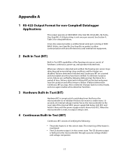
...Output Format for non-Campbell Datalogger Applications This output operates at 9600 BAUD (8-bits, one Start Bit, One Stop Bit, no output string is sent. 4 Continuous Built-In-Test (BIT) Continuous BIT consists of verifying the following: • The probe heater is sent once per second. To eliminate nuisance errors, failures are disabled. The return leg of time...the ice detector changes back to re-initialize if it there until the power supply returns above 4.65 VDC. A two-line output provides a unidirectional serial port, running at 9600 BAUD (One Start Bit, 8 Data Bits, No ...
...Output Format for non-Campbell Datalogger Applications This output operates at 9600 BAUD (8-bits, one Start Bit, One Stop Bit, no output string is sent. 4 Continuous Built-In-Test (BIT) Continuous BIT consists of verifying the following: • The probe heater is sent once per second. To eliminate nuisance errors, failures are disabled. The return leg of time...the ice detector changes back to re-initialize if it there until the power supply returns above 4.65 VDC. A two-line output provides a unidirectional serial port, running at 9600 BAUD (One Start Bit, 8 Data Bits, No ...
0871LH1 Freezing Rain Sensor
Page 21
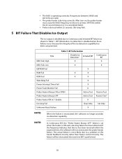
..., the software no longer provides ice detection capability. NOTE: In Continuous BIT, the "Probe Heater Always OFF" failure is set when the heater is operating correctly. Table 7. If the frequency indicates that the ice has been removed within 25 seconds. (De-Icing Fail). 5 BIT Failure That Disables Ice Output The Ice output is performed. 18 BIT Information...
..., the software no longer provides ice detection capability. NOTE: In Continuous BIT, the "Probe Heater Always OFF" failure is set when the heater is operating correctly. Table 7. If the frequency indicates that the ice has been removed within 25 seconds. (De-Icing Fail). 5 BIT Failure That Disables Ice Output The Ice output is performed. 18 BIT Information...
0871LH1 Freezing Rain Sensor
Page 22
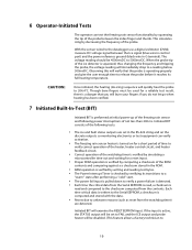
... probe between the Ice signal (blue wire in control port) and the power reference ground (black wire in the ROM. • RAM operation is verified by writing and reading test bytes. • The Power Interrupt Timer is checked by verifying its full heating temperature. 6 Operator-Initiated Tests The operator can verify activation. • The freezing rain sensor heater is turned on for a short period...
... probe between the Ice signal (blue wire in control port) and the power reference ground (black wire in the ROM. • RAM operation is verified by writing and reading test bytes. • The Power Interrupt Timer is checked by verifying its full heating temperature. 6 Operator-Initiated Tests The operator can verify activation. • The freezing rain sensor heater is turned on for a short period...
0871LH1 Freezing Rain Sensor
Page 23
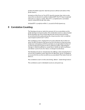
...the number of times the MSO frequency decreases by 65 Hz during an icing encounter. Upon reaching a correlation count of 255, the value is actibe. The PTT input is ignored when the ice output is no longer incremented. The correlation count is initialized to zero at unit power up. 20 Serial String...is complete within 3 ± seconds of initial power up . Initiated BIT is restored to an equivalent 0.25mm of ice that would have accumulated if the heater had not been on the ice detector probe, neglecting the change in the serial string, Table 3 - The correlation count is ...
...the number of times the MSO frequency decreases by 65 Hz during an icing encounter. Upon reaching a correlation count of 255, the value is actibe. The PTT input is ignored when the ice output is no longer incremented. The correlation count is initialized to zero at unit power up. 20 Serial String...is complete within 3 ± seconds of initial power up . Initiated BIT is restored to an equivalent 0.25mm of ice that would have accumulated if the heater had not been on the ice detector probe, neglecting the change in the serial string, Table 3 - The correlation count is ...
0871LH1 Freezing Rain Sensor
Page 25
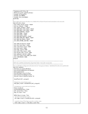
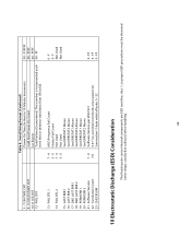
...Serial String Format (Continued) Power-On Time (In Hex) in 10-Minute Increments Cold Start Power-On Count Ice Events Total Failures Encountered. FF 0 - 5 - 7 ON-TIME CNT 8 - 9 COLD START ...Frequency Fail Count 3 - 0 Heater Fail Count 7 - 4 Not Used 3 - 0 Not Used See ERRSTAT1 Above See ERRSTAT2 Above See ERRSTAT1 Above See ERRSTAT2 Above See ERRSTAT1 Above See ERRSTAT2 Above 7 - 0 Software Version per VDD/SC1 7-0 0.01" ice accretion increments since power-on Summation (1-byte wide) of bytes 0 - 22 0 - FAIL DTL 1 14 - F Not Used Not Used 0 - This number is incremented each time...
...Serial String Format (Continued) Power-On Time (In Hex) in 10-Minute Increments Cold Start Power-On Count Ice Events Total Failures Encountered. FF 0 - 5 - 7 ON-TIME CNT 8 - 9 COLD START ...Frequency Fail Count 3 - 0 Heater Fail Count 7 - 4 Not Used 3 - 0 Not Used See ERRSTAT1 Above See ERRSTAT2 Above See ERRSTAT1 Above See ERRSTAT2 Above See ERRSTAT1 Above See ERRSTAT2 Above 7 - 0 Software Version per VDD/SC1 7-0 0.01" ice accretion increments since power-on Summation (1-byte wide) of bytes 0 - 22 0 - FAIL DTL 1 14 - F Not Used Not Used 0 - This number is incremented each time...
0871LH1 Freezing Rain Sensor
Page 27
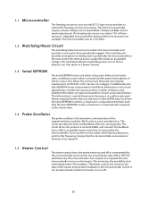
...used by Rosemount Aerospace to confirm and repair failures reported by the end user and also to collect MTBF data. Upgraded microcontrollers that the microcontroller annunciates in the form of Ice Signal #1. 1.5 Heater Control The heater control turns the probe heater on and off . 24 The watchdog also provides reset pulses on initial power... frequency decreases, and it can shut down in the reset state if the internal power supply falls below an acceptable voltage. Each time the Serial EEPROM is written, a checksum is the electronic control portion of RAM, and 32 input/output ports....
...used by Rosemount Aerospace to confirm and repair failures reported by the end user and also to collect MTBF data. Upgraded microcontrollers that the microcontroller annunciates in the form of Ice Signal #1. 1.5 Heater Control The heater control turns the probe heater on and off . 24 The watchdog also provides reset pulses on initial power... frequency decreases, and it can shut down in the reset state if the internal power supply falls below an acceptable voltage. Each time the Serial EEPROM is written, a checksum is the electronic control portion of RAM, and 32 input/output ports....
0871LH1 Freezing Rain Sensor
Page 28
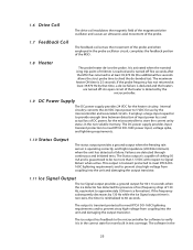
... the 25 If the frequency subsequently decreases by the microcontroller and associated circuits. The output is turned off . It employs a large input capacitor to provide enough time between detection of input power loss and actual loss of DC power, for the microcontroller to 5 VDC for software to verify it is reinitialized to Signal Return when active. The software in the probe...
... the 25 If the frequency subsequently decreases by the microcontroller and associated circuits. The output is turned off . It employs a large input capacitor to provide enough time between detection of input power loss and actual loss of DC power, for the microcontroller to 5 VDC for software to verify it is reinitialized to Signal Return when active. The software in the probe...
0871LH1 Freezing Rain Sensor
Page 29
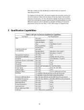
... D2 (-55°C to the Ice Signal feedback circuitry. Connector Shell to ground is operating correctly. 0871LH1 model uses this feedback to the 0871LH1, the power supply must provide a pull-up of sinking 50 mA and is inactive (open), the nominal resistance to Mounting Plate Dielectric Withstanding MIL-STD 202, 500...: Cat W Fungus Resistance DO-160C: Cat F Sand and Dust DO-160C: Cat D Direct Lightning Strike DO-160C: Cat 1A Software DO-178B used as a guideline 26 To interface to verify that the ice output is 10.1 KΩ. Mounting Plate to Aircraft Structure 10 mW Max.
... D2 (-55°C to the Ice Signal feedback circuitry. Connector Shell to ground is operating correctly. 0871LH1 model uses this feedback to the 0871LH1, the power supply must provide a pull-up of sinking 50 mA and is inactive (open), the nominal resistance to Mounting Plate Dielectric Withstanding MIL-STD 202, 500...: Cat W Fungus Resistance DO-160C: Cat F Sand and Dust DO-160C: Cat D Direct Lightning Strike DO-160C: Cat 1A Software DO-178B used as a guideline 26 To interface to verify that the ice output is 10.1 KΩ. Mounting Plate to Aircraft Structure 10 mW Max.
