
Parts Manual - English
Page 4
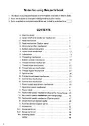
.... Power table 41 V1. Parts are circled by a dotted line L____] . Lubrication 15 H. Control box mechanism 31 R2. Feed mechanism 5 C2. Power supply equipment mechanism 39 T. Machine body 1 B. Feed mechanism (Option parts) 7 Ii Work clamp lifter mechanism 9 E. Lower shaft mechanism 13 G. Thread take-up mechanism 25 N. Accessories 53 Gal . Foot switch pedal mechanism (Except for using this parts book 1. Auxiliary device (Option parts) 51 Z. Parts supplied as complete assemblies are subject to changes...
.... Power table 41 V1. Parts are circled by a dotted line L____] . Lubrication 15 H. Control box mechanism 31 R2. Feed mechanism 5 C2. Power supply equipment mechanism 39 T. Machine body 1 B. Feed mechanism (Option parts) 7 Ii Work clamp lifter mechanism 9 E. Lower shaft mechanism 13 G. Thread take-up mechanism 25 N. Accessories 53 Gal . Foot switch pedal mechanism (Except for using this parts book 1. Auxiliary device (Option parts) 51 Z. Parts supplied as complete assemblies are subject to changes...

Parts Manual - English
Page 59
... SHANK BUTTON CLAMP BRACKET BUTTON CLAMP, A BUTTON CLAMP, B SCREW, PAN SM3.57-40X8 WASHER BUTTON PRESSER STUD SPRING SET SCREW COLLAR SCREW, PAN SM3.57-40X7 BUTTON PRESSER ARM SET SCREW, (CP) SM4.76 BUTTON PRESSER SET SCREW, (CP) SM4.37-40X8 BUTTON PRESSER ARM LIFTER BUTTON PRESSER ARM LIFTER STUD SET SCREW, SOCKET (CP) SM4.37 FEED PLATE BASE FEED PLATE, ;SHANK BUTTON SCREW, SM4.76 NUT, 2 SM4.76 WASHER, PLAIN SM4.76 CLOTH RECEIVER, S SCREW, BIND SM3.57-40X5 MOVABLE KNIFE ASSY, LL NEEDLE ASSY, TQX7 (#16) SHUTTLE RACE THREAD GUIDE NEEDLE HOLE PLATE, E THREAD GUIDE, B ;N-BAR SCREW...
... SHANK BUTTON CLAMP BRACKET BUTTON CLAMP, A BUTTON CLAMP, B SCREW, PAN SM3.57-40X8 WASHER BUTTON PRESSER STUD SPRING SET SCREW COLLAR SCREW, PAN SM3.57-40X7 BUTTON PRESSER ARM SET SCREW, (CP) SM4.76 BUTTON PRESSER SET SCREW, (CP) SM4.37-40X8 BUTTON PRESSER ARM LIFTER BUTTON PRESSER ARM LIFTER STUD SET SCREW, SOCKET (CP) SM4.37 FEED PLATE BASE FEED PLATE, ;SHANK BUTTON SCREW, SM4.76 NUT, 2 SM4.76 WASHER, PLAIN SM4.76 CLOTH RECEIVER, S SCREW, BIND SM3.57-40X5 MOVABLE KNIFE ASSY, LL NEEDLE ASSY, TQX7 (#16) SHUTTLE RACE THREAD GUIDE NEEDLE HOLE PLATE, E THREAD GUIDE, B ;N-BAR SCREW...
Instruction Manual - English
Page 3
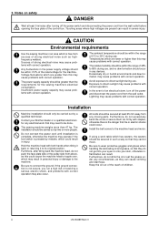
... not connect the power cord until installation is complete, otherwise the machine may operate if the foot switch is not secure, you run a high risk of the control box. Furthmore, after turning off the power and disconnect the power cord from the wall outlet before opening the face plate of receiving a serious electric shock, and problems with correct operation may need to wear protective goggles...
... not connect the power cord until installation is complete, otherwise the machine may operate if the foot switch is not secure, you run a high risk of the control box. Furthmore, after turning off the power and disconnect the power cord from the wall outlet before opening the face plate of receiving a serious electric shock, and problems with correct operation may need to wear protective goggles...
Instruction Manual - English
Page 4
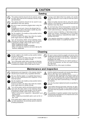
... needle up stop position before using a work table which might cause the needle to the needle up stop position before turning on when carrying out some adjustment, be absolutely sure to re-install them to break. If the machine develops a problem, contact your nearest Brother dealer or a qualified technician. Be sure to break. Turn off the power switch at the following times, otherwise the machine may operate if the foot...
... needle up stop position before using a work table which might cause the needle to the needle up stop position before turning on when carrying out some adjustment, be absolutely sure to re-install them to break. If the machine develops a problem, contact your nearest Brother dealer or a qualified technician. Be sure to break. Turn off the power switch at the following times, otherwise the machine may operate if the foot...
Instruction Manual - English
Page 5
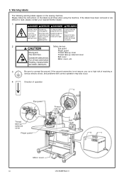
... switch before opening this cover. Thread take -up solenoid cover Operate with correct operation may cause injury. Please follow the instructions on the sewing machine. If the labels have been removed or are difficult to connect the ground. Turn off main switch and wait 5 minutes before Belt cover Motor cover, etc. threading, changing bobbin and needle, cleaning etc. 3 Be sure to read, please contact your nearest Brother dealer. 1 Hazardous...
... switch before opening this cover. Thread take -up solenoid cover Operate with correct operation may cause injury. Please follow the instructions on the sewing machine. If the labels have been removed or are difficult to connect the ground. Turn off main switch and wait 5 minutes before Belt cover Motor cover, etc. threading, changing bobbin and needle, cleaning etc. 3 Be sure to read, please contact your nearest Brother dealer. 1 Hazardous...
Instruction Manual - English
Page 6
... 9-6. Adjusting the driver needle guard ..... 31 10-4. SPECIFICATIONS 02 2-1. Power table 6 3-2. Installing the cushions 9 3-8. Installing the button tray 15 3-20. CORRECT USE 21 7-1. DIP switches inside the control box 42 12-4. Using the cycle sewing function ........ 47 14.TABLE OF ERROR CODES 49 15.GAUGE PARTS LIST 51 16.TROUBLESHOOTING 52 17.OPTIONAL PARTS 55 LK3-B438E Mark II Installing the machine head 10 3-9. Installing the belt cover 14 3-16. Inserting the button 25 7-8. Adjustment by the accessory spring 25 8. Adjusting the...
... 9-6. Adjusting the driver needle guard ..... 31 10-4. SPECIFICATIONS 02 2-1. Power table 6 3-2. Installing the cushions 9 3-8. Installing the button tray 15 3-20. CORRECT USE 21 7-1. DIP switches inside the control box 42 12-4. Using the cycle sewing function ........ 47 14.TABLE OF ERROR CODES 49 15.GAUGE PARTS LIST 51 16.TROUBLESHOOTING 52 17.OPTIONAL PARTS 55 LK3-B438E Mark II Installing the machine head 10 3-9. Installing the belt cover 14 3-16. Inserting the button 25 7-8. Adjustment by the accessory spring 25 8. Adjusting the...

Instruction Manual - English
Page 8
... needle lock stitch Maximum sewing speed 2,500rpm Maximum pattern size 0 - 6.4 × 0 - 6.4 mm Needle TQ × 1#12 Dimensions of buttons that can be added is within 10,000.) Motor Three-phase 400W induction motor Weights Machine head: 47kg, Operation panel: 0.6kg, Control box: 9 - 19kg (depending on destination) Power source Single-phase 220 - 230V 3-phase 220, 380, 400, 415V Maximum electric power consumption; 600VA LK3-B438E Mark II 2 Total number of stitches...
... needle lock stitch Maximum sewing speed 2,500rpm Maximum pattern size 0 - 6.4 × 0 - 6.4 mm Needle TQ × 1#12 Dimensions of buttons that can be added is within 10,000.) Motor Three-phase 400W induction motor Weights Machine head: 47kg, Operation panel: 0.6kg, Control box: 9 - 19kg (depending on destination) Power source Single-phase 220 - 230V 3-phase 220, 380, 400, 415V Maximum electric power consumption; 600VA LK3-B438E Mark II 2 Total number of stitches...

Instruction Manual - English
Page 10
of Standard Standard stitches sewing length X sewing width Y 19 17 8-7 1 23 30 10-9 1 27 18 6-6 1 20 19 8-8 1 24 3.4mm 3.4mm 31 10-10 1 28 45 *3 20 *3 32 ...using the programs. * 2 Do not use the button lifter spring. * 3 Thread is trimmed after sewing of crossover stitches 1 No. of threads 6-5 2 . Program No. of button holes 16 Sewing pattern No. LK3-B438E Mark II 4 To continue sewing to be sewn. No. SPECIFICATIONS No. of the first side is no crossover thread to the end, keep the foot switch depressed until sewing of the other side starts...
of Standard Standard stitches sewing length X sewing width Y 19 17 8-7 1 23 30 10-9 1 27 18 6-6 1 20 19 8-8 1 24 3.4mm 3.4mm 31 10-10 1 28 45 *3 20 *3 32 ...using the programs. * 2 Do not use the button lifter spring. * 3 Thread is trimmed after sewing of crossover stitches 1 No. of threads 6-5 2 . Program No. of button holes 16 Sewing pattern No. LK3-B438E Mark II 4 To continue sewing to be sewn. No. SPECIFICATIONS No. of the first side is no crossover thread to the end, keep the foot switch depressed until sewing of the other side starts...

Instruction Manual - English
Page 20
... i, bolt o, spring washer !0 and flat washer !1 as shown in Figure A. ♦If foot switch support plate B !3 is used , for example, if it is removed. 2. LK3-B438E Mark II 14 If the foot switch is used in a back-to the belt cover. 3-16. Loosen the two screws w of the upper cover q and the two screws r of the control box q. 2. Install the foot switch e to the work table leg, move the foot switch...
... i, bolt o, spring washer !0 and flat washer !1 as shown in Figure A. ♦If foot switch support plate B !3 is used , for example, if it is removed. 2. LK3-B438E Mark II 14 If the foot switch is used in a back-to the belt cover. 3-16. Loosen the two screws w of the upper cover q and the two screws r of the control box q. 2. Install the foot switch e to the work table leg, move the foot switch...

Instruction Manual - English
Page 28
... button is com- WIND switch w after a set screw t and pull the bobbin presser q outward. bin winder thread tension stud w clockwise; WIND switch w. 5. CORRECT USE 7-4 . Turn on the power switch. (The POWER indicator on . 6. Winding the lower thread CAUTION Do not touch or place anything against any of the bobbin capacity ) has been wound on the operation panel will automatically return to its original position after the machine starts operating. If you release the foot...
... button is com- WIND switch w after a set screw t and pull the bobbin presser q outward. bin winder thread tension stud w clockwise; WIND switch w. 5. CORRECT USE 7-4 . Turn on the power switch. (The POWER indicator on . 6. Winding the lower thread CAUTION Do not touch or place anything against any of the bobbin capacity ) has been wound on the operation panel will automatically return to its original position after the machine starts operating. If you release the foot...

Instruction Manual - English
Page 29
... lever is not used. 23 LK3-B438E Mark II Turn the tension nut q(main tension) to open it out proximately 30 mm of the arrow when the thread is held. Replacing the bobbin case and threading the thread CAUTION Turn off the power switch before removing and replacing the bobbin case, otherwise the machine may operate if the foot switch is depressed by its own weight while the thread end coming out of upper thread...
... lever is not used. 23 LK3-B438E Mark II Turn the tension nut q(main tension) to open it out proximately 30 mm of the arrow when the thread is held. Replacing the bobbin case and threading the thread CAUTION Turn off the power switch before removing and replacing the bobbin case, otherwise the machine may operate if the foot switch is depressed by its own weight while the thread end coming out of upper thread...

Instruction Manual - English
Page 32
... material, release the foot switch. Insert the button to the button holder. (Refer to the machine. LK3-B438E Mark II 26 SEWING 8. Inserting the button".) 4. Depress the foot switch to the 1st step, the button clamp will flash in injury. • Threading • When replacing the needle • When not using the machine and when leaving the machine unattended. When the foot switch is pressed to shift the position of the moving...
... material, release the foot switch. Insert the button to the button holder. (Refer to the machine. LK3-B438E Mark II 26 SEWING 8. Inserting the button".) 4. Depress the foot switch to the 1st step, the button clamp will flash in injury. • Threading • When replacing the needle • When not using the machine and when leaving the machine unattended. When the foot switch is pressed to shift the position of the moving...

Instruction Manual - English
Page 44
... memory setting. Press the SELECT switch q until the Y-SCALE indicator w illuminates. 3. While pressing the TEST switch e, press the RESET switch r. 4. In such cases, carry out the following procedure to the normal condition. 10-15. Turn on the power. This will be shown in the table above. 5. STANDARD ADJUSTMENTS B430E ɹɹɹSeries POWER P PROGRAM NO. LK3-B438E Mark...
... memory setting. Press the SELECT switch q until the Y-SCALE indicator w illuminates. 3. While pressing the TEST switch e, press the RESET switch r. 4. In such cases, carry out the following procedure to the normal condition. 10-15. Turn on the power. This will be shown in the table above. 5. STANDARD ADJUSTMENTS B430E ɹɹɹSeries POWER P PROGRAM NO. LK3-B438E Mark...
Instruction Manual - English
Page 51
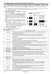
... used for checking feeding operation.) memo-0F After sewing is set will be sewn in the display window will change from 30 to 4F BOBBIN.WIND SELECT will be lifted. (The button clamp rises at the final stitch to enable the quick taking out of the sewing frame.) - - When the BOBBIN. The sewing start point via mechanical home position. 13. NOTE: After changing the memory switch settings, press the power...
... used for checking feeding operation.) memo-0F After sewing is set will be sewn in the display window will change from 30 to 4F BOBBIN.WIND SELECT will be lifted. (The button clamp rises at the final stitch to enable the quick taking out of the sewing frame.) - - When the BOBBIN. The sewing start point via mechanical home position. 13. NOTE: After changing the memory switch settings, press the power...
Instruction Manual - English
Page 55
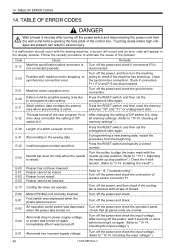
... settings".) E-40 Length of the problem. Foot switch was depressed when the power was turned on again immediately after turning off the power, wait 3 seconds or more before opening the face plate of presser sensor connector P1. Stitch pattern data overlaps the sewing area when area limiting is not raised. E-50 E-60 E-61 E-62 E-63 E-70 E-80 E-81 E-82 Needle bar does not stop position...
... settings".) E-40 Length of the problem. Foot switch was depressed when the power was turned on again immediately after turning off the power, wait 3 seconds or more before opening the face plate of presser sensor connector P1. Stitch pattern data overlaps the sewing area when area limiting is not raised. E-50 E-60 E-61 E-62 E-63 E-70 E-80 E-81 E-82 Needle bar does not stop position...

Instruction Manual - English
Page 58
...-up lever stroke. Button clamp lift amount is obstructing the needle. 16. LK3-B438E Mark II 52 Distance between button clamp and top of needle plate within 17 mm. Link return spring is incorrect. Thread winding amount Adjust the position of the thread 36 wiper. Clearance beween thread wiper and needle tip Thread wiper position Adjust the height of the thread wiper. 36 Adjust the operating distance of the bobbin presser. 22 Stitches being skipped at the sewing start. Hook...
...-up lever stroke. Button clamp lift amount is obstructing the needle. 16. LK3-B438E Mark II 52 Distance between button clamp and top of needle plate within 17 mm. Link return spring is incorrect. Thread winding amount Adjust the position of the thread 36 wiper. Clearance beween thread wiper and needle tip Thread wiper position Adjust the height of the thread wiper. 36 Adjust the operating distance of the bobbin presser. 22 Stitches being skipped at the sewing start. Hook...

Instruction Manual - English
Page 59
...installed incorrectly. Lower thread tension Damage Needle clearance Needle bar lift amount Clearance between needle and rotary hook tip is too strong. Refer to "6 CHECKING THE 20 SEWING PATTERN". Needle and thread Use the correct needle for the needle. 21 Adjust the tension and height of needle hole plate or bobbin care are incorrect. TROUBLESHOOTING Problem Cause Check Remedy Page Upper thread breaks. Thread melting (synthetic thread) Thread and needle Thread take-up spring tension and height Damage or burring Thread edge Adjust the upper thread tension. 23 Install...
...installed incorrectly. Lower thread tension Damage Needle clearance Needle bar lift amount Clearance between needle and rotary hook tip is too strong. Refer to "6 CHECKING THE 20 SEWING PATTERN". Needle and thread Use the correct needle for the needle. 21 Adjust the tension and height of needle hole plate or bobbin care are incorrect. TROUBLESHOOTING Problem Cause Check Remedy Page Upper thread breaks. Thread melting (synthetic thread) Thread and needle Thread take-up spring tension and height Damage or burring Thread edge Adjust the upper thread tension. 23 Install...

Instruction Manual - English
Page 60
... 23 Upper thread is too weak. Needle down setting LK3-B438E Mark II Adjust the lower thread tension. 23 Adjust the tension and height of the 24 thread take -up spring. Upper thread tension Adjust the upper thread tension. 23 Lower thread tension is too long. Poor seam finish on reverse side of the shuttle race 31 thread guide. Button breaks. Incorrect needle and rotary hook timing. Upper thread is blunt. Adjust the position of material. Adjust the needle bar lift amount. 30 Adjust the position of the shuttle race 31 thread guide. Lower thread tension Thread...
... 23 Upper thread is too weak. Needle down setting LK3-B438E Mark II Adjust the lower thread tension. 23 Adjust the tension and height of the 24 thread take -up spring. Upper thread tension Adjust the upper thread tension. 23 Lower thread tension is too long. Poor seam finish on reverse side of the shuttle race 31 thread guide. Button breaks. Incorrect needle and rotary hook timing. Upper thread is blunt. Adjust the position of material. Adjust the needle bar lift amount. 30 Adjust the position of the shuttle race 31 thread guide. Lower thread tension Thread...
Hand Book - English
Page 1
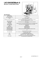
stitch number Work clamp lifter Hook Wiper device Thread trimmer device Thread take-up device Data storage method No. of cycle programs No. electric power consumption; 600VA 2000.7 LK3−B438E Mark II 1/9 of user programs No. Total number of stitches of button that can be sewn Button clamp height Feed mechanism Stitch length No. LK3-B438EMark II Electronic Lockstitch Button Sewer Specifications Stitch formation Max. of 20 mm or more.) Space between the...
stitch number Work clamp lifter Hook Wiper device Thread trimmer device Thread take-up device Data storage method No. of cycle programs No. electric power consumption; 600VA 2000.7 LK3−B438E Mark II 1/9 of user programs No. Total number of stitches of button that can be sewn Button clamp height Feed mechanism Stitch length No. LK3-B438EMark II Electronic Lockstitch Button Sewer Specifications Stitch formation Max. of 20 mm or more.) Space between the...

Hand Book - English
Page 7
...-40 × 7 Button presser arm Set screw, (CP) SM4.76 Button presser Set screw, (CP) SM4.37-40 × 8 Button presser arm lifter Button presser arm lifter stud Set screw, socket (CP) SM4.37 Feed plate base Feed plate, ;shank button Screw, SM4.76 Nut, 2 SM4.76 Washer, plain SM4.76 Cloth receiver, S Screw, bind SM3.57-40 × 5 Movable knife assy, LL Needle assy, TQ × 7 (#16) Shuttle race thread guide Needle hole plate, E Thread guide, B ;Needle bar Screw, w/socket SM4.37 Cloth receiver, M Part code Q'ty 156440...
...-40 × 7 Button presser arm Set screw, (CP) SM4.76 Button presser Set screw, (CP) SM4.37-40 × 8 Button presser arm lifter Button presser arm lifter stud Set screw, socket (CP) SM4.37 Feed plate base Feed plate, ;shank button Screw, SM4.76 Nut, 2 SM4.76 Washer, plain SM4.76 Cloth receiver, S Screw, bind SM3.57-40 × 5 Movable knife assy, LL Needle assy, TQ × 7 (#16) Shuttle race thread guide Needle hole plate, E Thread guide, B ;Needle bar Screw, w/socket SM4.37 Cloth receiver, M Part code Q'ty 156440...


