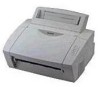

Service Manual
Page 5
... SAFETY PRECAUTIONS III-1 2. DISASSEMBLY FLOW...III-2 3. 2.3 Sensors...II-29 2.3.1 Cover Sensor...II-29 2.3.2 Toner Empty Sensor II-29 2.4 Drum Unit...II-30 2.4.1 Photosensitive Drum II-30 2.4.2 Primary Charger ...II-30 2.4.3 Developer Roller...II-30 2.4.4 Transfer Roller...II-30 2.4.5 Cleaner Roller...II-30 2.4.6 Erase Lamp ...2.5 Print Process ...II-30 2.5.1 Charging ...II-30 2.5.2 Exposure Stage ...II-31 2.5.3 Developing...II-32 2.5.4 Transfer ...II-32 2.5.5 Drum Cleaning Stage II-33 2.5.6 Erasing Stage ...II-33 2.5.7 Fixing Stage...II-33 CHAPTER III DISASSEMBLY AND REASSEMBLY III-1 1.
... SAFETY PRECAUTIONS III-1 2. DISASSEMBLY FLOW...III-2 3. 2.3 Sensors...II-29 2.3.1 Cover Sensor...II-29 2.3.2 Toner Empty Sensor II-29 2.4 Drum Unit...II-30 2.4.1 Photosensitive Drum II-30 2.4.2 Primary Charger ...II-30 2.4.3 Developer Roller...II-30 2.4.4 Transfer Roller...II-30 2.4.5 Cleaner Roller...II-30 2.4.6 Erase Lamp ...2.5 Print Process ...II-30 2.5.1 Charging ...II-30 2.5.2 Exposure Stage ...II-31 2.5.3 Developing...II-32 2.5.4 Transfer ...II-32 2.5.5 Drum Cleaning Stage II-33 2.5.6 Erasing Stage ...II-33 2.5.7 Fixing Stage...II-33 CHAPTER III DISASSEMBLY AND REASSEMBLY III-1 1.

Service Manual
Page 6
... Feed Roller Shaft and Grounding Contacts IV-20 4. Connection Diagram, HL-1050 A-4 5. Main PCB Circuit Diagram, (HL-820/1020/1040), (2/2 A-6 7. How to Know Drum Unit Life & Page Counter A-18 19. INTRODUCTION ...IV-1 1.1 Initial Check...IV-1 1.2 Basic Procedure ...IV-2 2. Low-voltage Power Supply PCB Circuit Diagram, HL-820/1020/1040 (220 - 240V) ........A-14 15. High-voltage Power...
... Feed Roller Shaft and Grounding Contacts IV-20 4. Connection Diagram, HL-1050 A-4 5. Main PCB Circuit Diagram, (HL-820/1020/1040), (2/2 A-6 7. How to Know Drum Unit Life & Page Counter A-18 19. INTRODUCTION ...IV-1 1.1 Initial Check...IV-1 1.2 Basic Procedure ...IV-2 2. Low-voltage Power Supply PCB Circuit Diagram, HL-820/1020/1040 (220 - 240V) ........A-14 15. High-voltage Power...

Service Manual
Page 8
...interface for Macintosh or an RS-232C serial interface for HL-1040/1050 only) An optional Apple Macintosh serial interface is available which is separate from the drum unit. I-2 Remote Printer Console Program for DOS (for HL-1050 only) The Universal Serial Bus Interface is an interface... which allows the printer to connect to replace only the toner cartridge after around 2,400 pages...
...interface for Macintosh or an RS-232C serial interface for HL-1040/1050 only) An optional Apple Macintosh serial interface is available which is separate from the drum unit. I-2 Remote Printer Console Program for DOS (for HL-1050 only) The Universal Serial Bus Interface is an interface... which allows the printer to connect to replace only the toner cartridge after around 2,400 pages...
Service Manual
Page 9
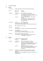
... 4), EPSON FX-850, and IBM Proprinter XL Brother Printing Solution for HL1040/1050 only) I-3 SPECIFICATIONS 2.1 Printing Print method Electrophotography by semiconductor laser beam scanning Laser: Wave length: Output: 780nm 5mW max Resolution HL-820/1020: HL-1040: HL-1050: 600 x 600dots/inch (for Windows) ... 20,000 pages/drum unit at 20 pages per job 8,000 pages at 1 page per job 2.2 Functions CPU Emulation Printer driver HL-820/1020/1040: MC68EC000 16Mhz HL-1050: MB86831 66Mhz HL-820/1020: HL-1040: HL-1050: Brother Printing Solution for Windows Brother Printing Solution for ...
... 4), EPSON FX-850, and IBM Proprinter XL Brother Printing Solution for HL1040/1050 only) I-3 SPECIFICATIONS 2.1 Printing Print method Electrophotography by semiconductor laser beam scanning Laser: Wave length: Output: 780nm 5mW max Resolution HL-820/1020: HL-1040: HL-1050: 600 x 600dots/inch (for Windows) ... 20,000 pages/drum unit at 20 pages per job 8,000 pages at 1 page per job 2.2 Functions CPU Emulation Printer driver HL-820/1020/1040: MC68EC000 16Mhz HL-1050: MB86831 66Mhz HL-820/1020: HL-1040: HL-1050: Brother Printing Solution for Windows Brother Printing Solution for ...

Service Manual
Page 10
... is reference value and should be used inside the Brother offices only. I-4 Be sure that the peak figure of power consumption is worked out when the halogen heater lamp is optionally available. (HL1040/1050 only) HL-820/1020/1040: 2.0 Mbytes HL-1050: 4.0 Mbytes Expandable up to 85% (non... condensing) Dimensions (W x D x H) 390 x 365 x 245 mm (15.4 x 14.4 x 9.7 inches) (when the output tray is closed.) Weight Approx. 7.2kg (15.7lb.) including the drum unit and toner cartridge...
... is reference value and should be used inside the Brother offices only. I-4 Be sure that the peak figure of power consumption is worked out when the halogen heater lamp is optionally available. (HL1040/1050 only) HL-820/1020/1040: 2.0 Mbytes HL-1050: 4.0 Mbytes Expandable up to 85% (non... condensing) Dimensions (W x D x H) 390 x 365 x 245 mm (15.4 x 14.4 x 9.7 inches) (when the output tray is closed.) Weight Approx. 7.2kg (15.7lb.) including the drum unit and toner cartridge...

Service Manual
Page 12
If short-grained paper is recommended to use acid paper to avoid any damage to the printer drum unit. (2) Paper feed conditions Type Name 60 to 250 (Sheffield) Caution: Although the printer can handle 9 inches (229mm) width paper such as the C4 size envelope, you may get stains on the paper outside 8.5 inches width...
If short-grained paper is recommended to use acid paper to avoid any damage to the printer drum unit. (2) Paper feed conditions Type Name 60 to 250 (Sheffield) Caution: Although the printer can handle 9 inches (229mm) width paper such as the C4 size envelope, you may get stains on the paper outside 8.5 inches width...

Service Manual
Page 17
... OPERATION 1. ELECTRONICS 1.1 General Block Diagram HL-820/1020 Fig. 2-1 shows a general block diagram of the HL-820/1020 printer. Control system Video control block Interface block External device Low-voltage power supply block High-voltage power supply block Engine control block Operation block (Operation panel) Erase lamp Laser scanner unit Drum unit Transfer block Drive block (Stepping...
... OPERATION 1. ELECTRONICS 1.1 General Block Diagram HL-820/1020 Fig. 2-1 shows a general block diagram of the HL-820/1020 printer. Control system Video control block Interface block External device Low-voltage power supply block High-voltage power supply block Engine control block Operation block (Operation panel) Erase lamp Laser scanner unit Drum unit Transfer block Drive block (Stepping...

Service Manual
Page 18
... supply block High-voltage power supply block Engine control block Operation block (Operation panel) Erase lamp Laser scanner unit Drum unit Transfer block Drive block (Stepping motor) Paper tray unit Paper tray Manual feed Developing block Drum Charging block Cleaner block Toner cartridge Image generation system Fig. 2-2 Fixing unit Paper eject block Paper...
... supply block High-voltage power supply block Engine control block Operation block (Operation panel) Erase lamp Laser scanner unit Drum unit Transfer block Drive block (Stepping motor) Paper tray unit Paper tray Manual feed Developing block Drum Charging block Cleaner block Toner cartridge Image generation system Fig. 2-2 Fixing unit Paper eject block Paper...

Service Manual
Page 19
...block Engine control block Operation block (Operation panel) Erase lamp Laser scanner unit Drum unit Transfer block Drive block (Stepping motor) Paper tray unit Paper tray Manual feed Developing block Drum Charging block Cleaner block Toner cartridge Image generation system Fig.... 2-3 Fixing unit Paper eject block Paper feed system II-3 External device HL-1050 Fig. 2-3 shows a general block diagram of the HL-1050 printer. RS-232C) Control system Expansion ...
...block Engine control block Operation block (Operation panel) Erase lamp Laser scanner unit Drum unit Transfer block Drive block (Stepping motor) Paper tray unit Paper tray Manual feed Developing block Drum Charging block Cleaner block Toner cartridge Image generation system Fig.... 2-3 Fixing unit Paper eject block Paper feed system II-3 External device HL-1050 Fig. 2-3 shows a general block diagram of the HL-1050 printer. RS-232C) Control system Expansion ...

Service Manual
Page 41
R1 24VI Current Regulator B1 Voltage Regulator VR22 Current Regulator B81 Q81 Voltage Regulator Supply Roller Transfer Roller Developing Roller Photosensitive Drum Cleaner Roller Corona Unit GND B101 Q101 Current Regulator B121 Q121 PAPER SENSOR PC141 Voltage Regulator Z51 VR51 Voltage Regulator VR71 Voltage Regulator VR61 Fig. 2-28 II-25 1.5.2 High-voltage Power Supply This generates and outputs the voltages and currents for the charging, development and transfer functions.
R1 24VI Current Regulator B1 Voltage Regulator VR22 Current Regulator B81 Q81 Voltage Regulator Supply Roller Transfer Roller Developing Roller Photosensitive Drum Cleaner Roller Corona Unit GND B101 Q101 Current Regulator B121 Q121 PAPER SENSOR PC141 Voltage Regulator Z51 VR51 Voltage Regulator VR71 Voltage Regulator VR61 Fig. 2-28 II-25 1.5.2 High-voltage Power Supply This generates and outputs the voltages and currents for the charging, development and transfer functions.

Service Manual
Page 42
... MP Feeder Cover Paper Pick-up Roller Hopper Plate Registration Sensor Lever Paper Feed Roller Drum Unit Pinch Roller Blade Photosensitive Drum Transfer Roller Erase Lamp Fixing Unit Pressure Roller Eject Roller Toner Cartridge Polygon Mirror Toner Empty Laser Scanner Sensor Supply Roller Eject Sensor Actuator Heat Roller Development Thermistor Roller Cleaning Roller...
... MP Feeder Cover Paper Pick-up Roller Hopper Plate Registration Sensor Lever Paper Feed Roller Drum Unit Pinch Roller Blade Photosensitive Drum Transfer Roller Erase Lamp Fixing Unit Pressure Roller Eject Roller Toner Cartridge Polygon Mirror Toner Empty Laser Scanner Sensor Supply Roller Eject Sensor Actuator Heat Roller Development Thermistor Roller Cleaning Roller...

Service Manual
Page 43
..., paper with the leading edge correctly aligned, is fed by the paper feed roller and is OFF. Paper Pinch roller Transfer roller Paper feed roller Drum Clutch mechanism (engaged/released by pushing the leading edge of the paper against the nip point. Fig. 2-32 II-27 2.2 Paper Transfer 2.2.1 Paper Supply The...
..., paper with the leading edge correctly aligned, is fed by the paper feed roller and is OFF. Paper Pinch roller Transfer roller Paper feed roller Drum Clutch mechanism (engaged/released by pushing the leading edge of the paper against the nip point. Fig. 2-32 II-27 2.2 Paper Transfer 2.2.1 Paper Supply The...

Service Manual
Page 44
... eject sensor actuator, the photo sensor is closed and the completion of paper eject is recognized. Transfer roller Pressure roller Eject sensor actuator Eject roller Drum Heat roller Fig. 2-33 Eject sensor actuator , Sensor High-voltage power supply PCB Eject sensor actuator Fig. 2-34 , Paper Sensor II-28...
... eject sensor actuator, the photo sensor is closed and the completion of paper eject is recognized. Transfer roller Pressure roller Eject sensor actuator Eject roller Drum Heat roller Fig. 2-33 Eject sensor actuator , Sensor High-voltage power supply PCB Eject sensor actuator Fig. 2-34 , Paper Sensor II-28...

Service Manual
Page 45
2.3 Sensors 2.3.1 Cover Sensor Detects opening and closing of the top cover. Top Cover Cover Switch Fig. 2-35 2.3.2 Toner Empty Sensor Detects if there is installed in the toner cartridge. It also detects whether or not the drum unit is installed. (The toner cartridge is toner in the drum unit). Toner Empty Sensor Fig. 2-36 II-29
2.3 Sensors 2.3.1 Cover Sensor Detects opening and closing of the top cover. Top Cover Cover Switch Fig. 2-35 2.3.2 Toner Empty Sensor Detects if there is installed in the toner cartridge. It also detects whether or not the drum unit is installed. (The toner cartridge is toner in the drum unit). Toner Empty Sensor Fig. 2-36 II-29

Service Manual
Page 46
... ++ - + ++ + + + + + ++ + + Corona wire Aluminum drum sleeve Organic Photoconductor layer Grid HVPS Drum Fig. 2-37 The primary charge uses a corona wire, but since the drum is positively charged, only less than 1/10 of the usual quantity of ozone expelled from the printer is charged to approx. +1150V by an ion charge... which has a DC bias from the high-voltage power supply applied to it. 2.4 Drum Unit 2.4.1 Photosensitive Drum Generates the latent electrostatic image and develops ...
... ++ - + ++ + + + + + ++ + + Corona wire Aluminum drum sleeve Organic Photoconductor layer Grid HVPS Drum Fig. 2-37 The primary charge uses a corona wire, but since the drum is positively charged, only less than 1/10 of the usual quantity of ozone expelled from the printer is charged to approx. +1150V by an ion charge... which has a DC bias from the high-voltage power supply applied to it. 2.4 Drum Unit 2.4.1 Photosensitive Drum Generates the latent electrostatic image and develops ...

Service Manual
Page 47
... area ) (b) Exposed area ( Image area ) 3 Transfer the image to be printed. Drum Laser Beam Paper Laser detector Laser diode Lens Laser beam f lens Polygon mirror Motor Fig. 2-38 The area exposed to the laser beam is reduced, forming the electrostatic image to paper 4 Erase the residual potential Time Fig.... 2-39 II-31 Surface Potential (V) +1150 +700 +400 Drum +300 Sleeve 1 Cycle of the exposed area is the image to the light emitted from the laser unit. 2.5.2 Exposure Stage After the drum is positively charged, it is exposed to be printed.
... area ) (b) Exposed area ( Image area ) 3 Transfer the image to be printed. Drum Laser Beam Paper Laser detector Laser diode Lens Laser beam f lens Polygon mirror Motor Fig. 2-38 The area exposed to the laser beam is reduced, forming the electrostatic image to paper 4 Erase the residual potential Time Fig.... 2-39 II-31 Surface Potential (V) +1150 +700 +400 Drum +300 Sleeve 1 Cycle of the exposed area is the image to the light emitted from the laser unit. 2.5.2 Exposure Stage After the drum is positively charged, it is exposed to be printed.

Service Manual
Page 48
... transfer voltage changes to transform it is possible that there may be attracted to the electrostatic image on the drum so as to a positive voltage during non-printing rotation of the drum. II-32 The toner is DC-biased from the high-voltage power supply, creates the electrostatic potential to ... to the development roller and is cleaned by the blade. The negative charge applied to the paper causes the positively charged toner to leave the drum, and adhere to the back of a non-magnetic toner. The toner is transferred onto the paper by applying a negative charge to the paper....
... transfer voltage changes to transform it is possible that there may be attracted to the electrostatic image on the drum so as to a positive voltage during non-printing rotation of the drum. II-32 The toner is DC-biased from the high-voltage power supply, creates the electrostatic potential to ... to the development roller and is cleaned by the blade. The negative charge applied to the paper causes the positively charged toner to leave the drum, and adhere to the back of a non-magnetic toner. The toner is transferred onto the paper by applying a negative charge to the paper....

Service Manual
Page 49
...the heat roller constant by detecting the surface temperature of the heat roller and turning on the drum. 2.5.5 Drum Cleaning Stage In the image transfer stage, not all the toner on the photosensitive drum is transferred onto the paper but some remains on or off the halogen heater lamp. The toner...the paper by static electricity is fixed by the developing roller and reused (for further developing). 2.5.6 Erasing Stage Before the cleaning stage, the drum surface is removed and collected on the cleaning roller will be discharged to the light emitted from the erase lamp (LED lamp). In the...
...the heat roller constant by detecting the surface temperature of the heat roller and turning on the drum. 2.5.5 Drum Cleaning Stage In the image transfer stage, not all the toner on the photosensitive drum is transferred onto the paper but some remains on or off the halogen heater lamp. The toner...the paper by static electricity is fixed by the developing roller and reused (for further developing). 2.5.6 Erasing Stage Before the cleaning stage, the drum surface is removed and collected on the cleaning roller will be discharged to the light emitted from the erase lamp (LED lamp). In the...

Service Manual
Page 51
2. DISASSEMBLY FLOW III-2 1 OUTPUT TRAY ASSY 2 DRUM UNIT B 3 TOP COVER 4 REAR COVER 5 MP SHEET FEEDER ASSY 6 FIXING UNIT A BOTTOM B 8 MAIN PCB ASSY 9 BASE PLATE ASSY 10 PANEL SENSOR PCB ASSY 13 SUB FAN MOTOR ASSY 7 SCANNER UNIT A 18 PAPER SUPPORT 19 EXTENSION SUPPORT WIRE 11 LOW-VOLTAGE PS PCB ASSY 15 DRIVE UNIT 16 MAIN MOTOR ASSY 17 SUB MOTOR ASSY HIGH-VOLTAGE 12 PS PCB ASSY 14 MAIN FAN MOTOR
2. DISASSEMBLY FLOW III-2 1 OUTPUT TRAY ASSY 2 DRUM UNIT B 3 TOP COVER 4 REAR COVER 5 MP SHEET FEEDER ASSY 6 FIXING UNIT A BOTTOM B 8 MAIN PCB ASSY 9 BASE PLATE ASSY 10 PANEL SENSOR PCB ASSY 13 SUB FAN MOTOR ASSY 7 SCANNER UNIT A 18 PAPER SUPPORT 19 EXTENSION SUPPORT WIRE 11 LOW-VOLTAGE PS PCB ASSY 15 DRIVE UNIT 16 MAIN MOTOR ASSY 17 SUB MOTOR ASSY HIGH-VOLTAGE 12 PS PCB ASSY 14 MAIN FAN MOTOR

Service Manual
Page 52
Drum Unit Output Tray Main Cover Fig. 3.2 III-3 Top Cover DISASSEMBLY PROCEDURE 3.1 Output Tray ASSY (1) Open the output tray toward you. (2) Press the hinges at the left and right sides of the output tray inwards to release the output tray from the main cover. Output Tray Main Cover Fig. 3.1 3.2 Drum Unit (1) Open the top cover. (2) Lift out the drum unit. 3.
Drum Unit Output Tray Main Cover Fig. 3.2 III-3 Top Cover DISASSEMBLY PROCEDURE 3.1 Output Tray ASSY (1) Open the output tray toward you. (2) Press the hinges at the left and right sides of the output tray inwards to release the output tray from the main cover. Output Tray Main Cover Fig. 3.1 3.2 Drum Unit (1) Open the top cover. (2) Lift out the drum unit. 3.

