Users Manual - English
Page 44
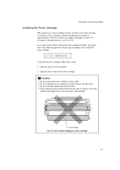
...toner cartridge on the printer without the toner cartridge installed, the display shows the following operator call message to prompt you turn on its end or turn it up to install the toner cartridge. 14 NO CARTRIDGE To install the toner cartridge, follow these steps: 1. Drum Shutter Fig. 2-10... Don'ts When Handling the Toner Cartridge 2-7 Open the bag to print. Open the top cover of the printer. 2. If you to approximately 9,000 A4 or letter-size single-sided pages at level...
...toner cartridge on the printer without the toner cartridge installed, the display shows the following operator call message to prompt you turn on its end or turn it up to install the toner cartridge. 14 NO CARTRIDGE To install the toner cartridge, follow these steps: 1. Drum Shutter Fig. 2-10... Don'ts When Handling the Toner Cartridge 2-7 Open the bag to print. Open the top cover of the printer. 2. If you to approximately 9,000 A4 or letter-size single-sided pages at level...

Users Manual - English
Page 215
... with the customer. s LABELS AND OVERHEAD TRANSPARENCIES The printer will print on most type of labels and transparencies designed for the quality and performance of a particular envelope because envelope properties are subject to the drum or rollers and cause jams and print quality problems.... PRINTER. Label and transparency sheets should have an adhesive that are rough, highly textured, or deeply embossed. 8. Envelopes which do not lie flat or that is acrylicbased since such material is more stable at the high temperatures in the User's Guide. Envelopes made with a laser printer....
... with the customer. s LABELS AND OVERHEAD TRANSPARENCIES The printer will print on most type of labels and transparencies designed for the quality and performance of a particular envelope because envelope properties are subject to the drum or rollers and cause jams and print quality problems.... PRINTER. Label and transparency sheets should have an adhesive that are rough, highly textured, or deeply embossed. 8. Envelopes which do not lie flat or that is acrylicbased since such material is more stable at the high temperatures in the User's Guide. Envelopes made with a laser printer....

Users Manual - English
Page 284
... 4−37 computer 2−15 continue mode 4−49 continue switch 4−67 control panel 2−3 copy switch 4−81 D data lamp 4−5 display 4−2 drum shutter 2−7 duplex mode 4−80 duplex unit 1−20, 3−10, 5−13 E economy switch 4−73 emulation 1−15 emulation mode 3−1, 4−...
... 4−37 computer 2−15 continue mode 4−49 continue switch 4−67 control panel 2−3 copy switch 4−81 D data lamp 4−5 display 4−2 drum shutter 2−7 duplex mode 4−80 duplex unit 1−20, 3−10, 5−13 E economy switch 4−73 emulation 1−15 emulation mode 3−1, 4−...
Service Manual
Page 4
...-6 3.2 2 Developing stage ...II-8 3.2 3 Transfer stage ...II-9 3.2 4 Fixing stage...II-10 3.2 5 Drum cleaning stage II-10 3.3 Operation ...II-11 4. PARTS OF THE PRINTER I-8 4.1 External Views ...I-8 4.2 Cross Sectional View ...I -1 1. Basic Sequence of Unsealed EP-ED HC Cartridges I... Paper Jam Detection...II-15 i BASIC OPERATIONS II-1 1.1. Mechanical Configuration...II-1 1.2. LASER/SCANNER SYSTEM II-4 3. CONTENTS CHAPTER I GENERAL I -9 5. SPECIFICATIONS I -7 4. SAFETY INFORMATION I-6 3.1 Laser Safety (110 - 120V Model only I-6 3.2 CDRH Regulations (110 - 120V Model only I-7 3.3 ...
...-6 3.2 2 Developing stage ...II-8 3.2 3 Transfer stage ...II-9 3.2 4 Fixing stage...II-10 3.2 5 Drum cleaning stage II-10 3.3 Operation ...II-11 4. PARTS OF THE PRINTER I-8 4.1 External Views ...I-8 4.2 Cross Sectional View ...I -1 1. Basic Sequence of Unsealed EP-ED HC Cartridges I... Paper Jam Detection...II-15 i BASIC OPERATIONS II-1 1.1. Mechanical Configuration...II-1 1.2. LASER/SCANNER SYSTEM II-4 3. CONTENTS CHAPTER I GENERAL I -9 5. SPECIFICATIONS I -7 4. SAFETY INFORMATION I-6 3.1 Laser Safety (110 - 120V Model only I-6 3.2 CDRH Regulations (110 - 120V Model only I-7 3.3 ...

Service Manual
Page 8
...need of the printer are directly detachable, and they require no adjustment after reassembly. 2. The internally-storable, front-loading paper cassette enables you to carry. E. The printer is designed into a single assembly called an "EP-ED HC cartridge". Laser beam safety ... high-speed, non-impact (low-noise) printer is easy with print component units which are combined into the printer. Maintenance is based on electrophotography, electronics and laser technology. FEATURES A. The charging roller, developing cylinder, photosensitive drum and cleaner of service call. CHAPTER I...
...need of the printer are directly detachable, and they require no adjustment after reassembly. 2. The internally-storable, front-loading paper cassette enables you to carry. E. The printer is designed into a single assembly called an "EP-ED HC cartridge". Laser beam safety ... high-speed, non-impact (low-noise) printer is easy with print component units which are combined into the printer. Maintenance is based on electrophotography, electronics and laser technology. FEATURES A. The charging roller, developing cylinder, photosensitive drum and cleaner of service call. CHAPTER I...

Service Manual
Page 9
...A5, ISO B6, A6 and approx. 20 envelopes. (8) Printing system Photosensitive drum Charging Exposure Development Paper feed Image transfer Separation Fixing Toner supply Life expectancy OPC Charging Roller Laser scanning system Toner projection development system Cassette or manual feed Roller method Natural(utilizing... a small drum radius), Static charge eliminator Heated fixing roller Included in the ...
...A5, ISO B6, A6 and approx. 20 envelopes. (8) Printing system Photosensitive drum Charging Exposure Development Paper feed Image transfer Separation Fixing Toner supply Life expectancy OPC Charging Roller Laser scanning system Toner projection development system Cassette or manual feed Roller method Natural(utilizing... a small drum radius), Static charge eliminator Heated fixing roller Included in the ...

Service Manual
Page 16
4.2 Cross Sectional View 2 3 4 1 6 5 7 14 13 12 11 8 10 9 1 Control panel 2 EP-ED HC cartridge 3 Photosensitive drum 4 Laser unit 5 Transfer unit 6 Face-down tray 7 Print-delivery path 8 Fixing unit 9 Low-voltage power supply assy 10 High-voltage power supply assy 11 Paper cassette (Tray 1) 12 Pick-up rollers 13 MP tray 14 Registration rollers Figure 1.5 I-9
4.2 Cross Sectional View 2 3 4 1 6 5 7 14 13 12 11 8 10 9 1 Control panel 2 EP-ED HC cartridge 3 Photosensitive drum 4 Laser unit 5 Transfer unit 6 Face-down tray 7 Print-delivery path 8 Fixing unit 9 Low-voltage power supply assy 10 High-voltage power supply assy 11 Paper cassette (Tray 1) 12 Pick-up rollers 13 MP tray 14 Registration rollers Figure 1.5 I-9

Service Manual
Page 17
... user, therefore, should be fully informed about the correct storage and handling of Unsealed EP-ED HC Cartridges Each EP-ED HC cartridge contains a photosensitive drum that has an organic photoconductor (OPC) which deteriorates when exposed to direct sunlight or near an air conditioner outlet). 3) Avoid dusty places or places exposed...
... user, therefore, should be fully informed about the correct storage and handling of Unsealed EP-ED HC Cartridges Each EP-ED HC cartridge contains a photosensitive drum that has an organic photoconductor (OPC) which deteriorates when exposed to direct sunlight or near an air conditioner outlet). 3) Avoid dusty places or places exposed...

Service Manual
Page 18
BASIC OPERATIONS 1.1 Mechanical Configuration The printer functions can be divided into four blocks: the laser system, the image formation system, the paper pick-up/feed system and the control system. solid thin arrows ( ) ...(2 slots) Optional I/O (MIO) Main PCB Delivery rollers Fixing unit Feeder External Device Control panel CONTROL SYSTEM IMAGE FORMATION SYSTEM Cleaning unit Photosensitive drum Developing unit Laser unit LASER SYSTEM Transfer separation unit MP tray PAPER PICK-UP/FEED SYSTEM Figure 2.1 Tray 1 Tray 2 (Option) II-1 Striped conduits ( ) indicate...
BASIC OPERATIONS 1.1 Mechanical Configuration The printer functions can be divided into four blocks: the laser system, the image formation system, the paper pick-up/feed system and the control system. solid thin arrows ( ) ...(2 slots) Optional I/O (MIO) Main PCB Delivery rollers Fixing unit Feeder External Device Control panel CONTROL SYSTEM IMAGE FORMATION SYSTEM Cleaning unit Photosensitive drum Developing unit Laser unit LASER SYSTEM Transfer separation unit MP tray PAPER PICK-UP/FEED SYSTEM Figure 2.1 Tray 1 Tray 2 (Option) II-1 Striped conduits ( ) indicate...

Service Manual
Page 19
...output from the main PCB, and the laser unit motor is controlled by the main motor, the paper feed motor and the laser unit motor. Figure 2.2 II-2 1.2 Main Drive The power necessary for driving the printer is supplied by the laser unit motor drive signal (SDRIVE) output from... the main PCB. Main motor Main motor drive signal (MDRIVE) Main PCB Drum gear Photosensitive drum Fixing unit Paper delivery rollers Paper feed motor Paper feed motor...
...output from the main PCB, and the laser unit motor is controlled by the main motor, the paper feed motor and the laser unit motor. Figure 2.2 II-2 1.2 Main Drive The power necessary for driving the printer is supplied by the laser unit motor drive signal (SDRIVE) output from... the main PCB. Main motor Main motor drive signal (MDRIVE) Main PCB Drum gear Photosensitive drum Fixing unit Paper delivery rollers Paper feed motor Paper feed motor...

Service Manual
Page 21
... lens and then brought to the laser unit. LASER SYSTEM To external device Main PCB SBD DATA VOFF Laser unit driver Collimator lens Cylindrical lens Scanning mirror Optical sensor Laser unit motor Focusing lenses Beam detect mirror Reflective mirror Photosensitive drum Figure 2.4 In response to the ... mirror. As the scanning mirror rotates at a constant speed, the laser beam scans the photosensitive drum at a constant speed. II-4 As the photosensitive drum rotates at a constant speed and the laser beam scans the drum, an images is reflected by DATA. 2. The path of the...
... lens and then brought to the laser unit. LASER SYSTEM To external device Main PCB SBD DATA VOFF Laser unit driver Collimator lens Cylindrical lens Scanning mirror Optical sensor Laser unit motor Focusing lenses Beam detect mirror Reflective mirror Photosensitive drum Figure 2.4 In response to the ... mirror. As the scanning mirror rotates at a constant speed, the laser beam scans the photosensitive drum at a constant speed. II-4 As the photosensitive drum rotates at a constant speed and the laser beam scans the drum, an images is reflected by DATA. 2. The path of the...

Service Manual
Page 22
... 2.6 1. The outer layer of the drum consists of the printer. Electrostatic latent image formation stage Step 1 Primary charge (-) Step 2 Scanning exposure 2. 3. Laser beam Primary charging roller Blade Cartridge Cleaning blade Photosensitive drum Static charge eliminator Developing cylinder Paper Transfer ...a TVDO signal, forms a toner image on the photosensitive drum. IMAGE FORMATION SYSTEM 3.1 Outline The image formation system is transferred onto the paper by the printer has a seamless photosensitive drum with the structure shown in Figure 2.5. The printing process ...
... 2.6 1. The outer layer of the drum consists of the printer. Electrostatic latent image formation stage Step 1 Primary charge (-) Step 2 Scanning exposure 2. 3. Laser beam Primary charging roller Blade Cartridge Cleaning blade Photosensitive drum Static charge eliminator Developing cylinder Paper Transfer ...a TVDO signal, forms a toner image on the photosensitive drum. IMAGE FORMATION SYSTEM 3.1 Outline The image formation system is transferred onto the paper by the printer has a seamless photosensitive drum with the structure shown in Figure 2.5. The printing process ...

Service Manual
Page 23
... stage 7. Separation 4. Charges are absent from the "light" areas, where the laser beam struck (exposed) the drum surface. Drum cleaning 3. Scanning exposure Paper path Direction of the stage, negative charges remain in the unexposed "dark" area. Fixing 5. ...4) charge (step 1) Figure 2.8 II-6 Develop ment Developing stage Print delivery Fixing stage 6. Since this image of electrical charges on the drum is invisible to the eye, it is called an "electrostatic latent image". Fixing stage Step 6 Fixing 5. Transfer Transfer stage Registration Cassette...
... stage 7. Separation 4. Charges are absent from the "light" areas, where the laser beam struck (exposed) the drum surface. Drum cleaning 3. Scanning exposure Paper path Direction of the stage, negative charges remain in the unexposed "dark" area. Fixing 5. ...4) charge (step 1) Figure 2.8 II-6 Develop ment Developing stage Print delivery Fixing stage 6. Since this image of electrical charges on the drum is invisible to the eye, it is called an "electrostatic latent image". Fixing stage Step 6 Fixing 5. Transfer Transfer stage Registration Cassette...

Service Manual
Page 24
...is applied to the primary charging roller to be neutralized in the areas struck by the beam. The printer uses the charging method that directly charges the drum for latent image formation, a uniform negative potential is changed with the developing DC bias. This charging ...consists of conductive rubber. This DC bias is applied to the photosensitive drum surface. Step 2 Scanning exposure Laser beam ___ +++ Unexposed area Exposed area Figure 2.10 When the laser beam scans the drum surface, it ,,,iv,,e, drum Figure 2.9 As preparation for the primary charge. Step 1 Primary ...
...is applied to the primary charging roller to be neutralized in the areas struck by the beam. The printer uses the charging method that directly charges the drum for latent image formation, a uniform negative potential is changed with the developing DC bias. This charging ...consists of conductive rubber. This DC bias is applied to the photosensitive drum surface. Step 2 Scanning exposure Laser beam ___ +++ Unexposed area Exposed area Figure 2.10 When the laser beam scans the drum surface, it ,,,iv,,e, drum Figure 2.9 As preparation for the primary charge. Step 1 Primary ...

Service Manual
Page 25
... to the drum surface and improve the contrast of the print. This changes the density of the printed image. This printer has a ...Development places particles of toner onto the areas of the drum that were exposed to the laser beam have been cleared of charge by magnetic attraction. ...Actually they are negative, but they are less negative) than the developing cylinder and explanation is an insulator, and acquires a negative charge by regarding them . II-8 The developing cylinder rotates around a fixed internal...
... to the drum surface and improve the contrast of the print. This changes the density of the printed image. This printer has a ...Development places particles of toner onto the areas of the drum that were exposed to the laser beam have been cleared of charge by magnetic attraction. ...Actually they are negative, but they are less negative) than the developing cylinder and explanation is an insulator, and acquires a negative charge by regarding them . II-8 The developing cylinder rotates around a fixed internal...

Service Manual
Page 26
...the paper due to jamming, etc., the toner may adhere to the drum. Reference: If the image on the transfer charging roller to the transfer charging roller. During wait, initial rotation, and last rotation, the printer sets the primary DC voltage to zero, and sets the charge on... the toner image is transferred from the transfer charging roller by the static charge eliminator after transfer. The printer removes the toner from the drum surface to separate from the drum. (Curvature separation) To stabilize the paper feed and prevent small white circles from appearing in the printed image...
...the paper due to jamming, etc., the toner may adhere to the drum. Reference: If the image on the transfer charging roller to the transfer charging roller. During wait, initial rotation, and last rotation, the printer sets the primary DC voltage to zero, and sets the charge on... the toner image is transferred from the transfer charging roller by the static charge eliminator after transfer. The printer removes the toner from the drum surface to separate from the drum. (Curvature separation) To stabilize the paper feed and prevent small white circles from appearing in the printed image...

Service Manual
Page 27
Step 6 Fixing Halogen heater Upper fixing roller Toner Paper Lower fixing roller Figure 2.15 The upper roller surface is cleaned off in the drum cleaning stage so that of the upper roller becoming higher than that the next print image will smear the image. The upper and lower ...in the transfer stage is held only by electrostatic attraction and slight physical adhesion, so even a light touch will be clear. Some remains on the drum surface is scraped away by heating the paper and applying pressure. II-10 In the fixing stage, the toner image is transferred to make a permanent...
Step 6 Fixing Halogen heater Upper fixing roller Toner Paper Lower fixing roller Figure 2.15 The upper roller surface is cleaned off in the drum cleaning stage so that of the upper roller becoming higher than that the next print image will smear the image. The upper and lower ...in the transfer stage is held only by electrostatic attraction and slight physical adhesion, so even a light touch will be clear. Some remains on the drum surface is scraped away by heating the paper and applying pressure. II-10 In the fixing stage, the toner image is transferred to make a permanent...

Service Manual
Page 28
... residual toner is removed from the drum surface with an alarm. When the output from this sensor falls below a certain level, it warns that the EP-ED HC cartridge will be out of toner with the cleaner blade. Laser unit Laser beam Reflection mirror EP-ED HC ... is converted into a visible image by the toner on the drum. After the drum surface is charged negatively by the primary charge roller, the laser beam modulated by a DATA signal scans the drum surface to rotate the photosensitive drum. 3.3 Operation When the engine controller circuit receives a print signal (PRINT) or a ...
... residual toner is removed from the drum surface with an alarm. When the output from this sensor falls below a certain level, it warns that the EP-ED HC cartridge will be out of toner with the cleaner blade. Laser unit Laser beam Reflection mirror EP-ED HC ... is converted into a visible image by the toner on the drum. After the drum surface is charged negatively by the primary charge roller, the laser beam modulated by a DATA signal scans the drum surface to rotate the photosensitive drum. 3.3 Operation When the engine controller circuit receives a print signal (PRINT) or a ...

Service Manual
Page 29
...Main motor drive signal (MDRIVE) Paper ejection sensor signal (EJECT) Figure 2.18 II-12 Main PCB Registration sensor Transfer roller Main motor Photosensitive drum Fixing rollers Paper ejection sensor Stuck-full sensor The paper position is detected by the registration sensor so that a paper jam has occurred. ... devise by a status signal. if printed paper has not reached or not cleared the paper ejection sensor in a specified time, the printer judges that the leading edge of the paper is deliveried to the face down to the circuit while the paper feed motor is engaged....
...Main motor drive signal (MDRIVE) Paper ejection sensor signal (EJECT) Figure 2.18 II-12 Main PCB Registration sensor Transfer roller Main motor Photosensitive drum Fixing rollers Paper ejection sensor Stuck-full sensor The paper position is detected by the registration sensor so that a paper jam has occurred. ... devise by a status signal. if printed paper has not reached or not cleared the paper ejection sensor in a specified time, the printer judges that the leading edge of the paper is deliveried to the face down to the circuit while the paper feed motor is engaged....

Service Manual
Page 30
... receives PRNT or PRFD signal from flashing to the photosensitive drum. This feeds paper to lighting. Timing chart for the pick-up roller solenoid 1.38 sec 2.54 sec 1.74 sec 0.12 sec 0.12 sec Figure 2.19 II-13 About 0.2 seconds later, the printer actuates the tray1 pick-up roller solenoid and the... sensor Paper ejection sensor Pick-up one rotation. 4.2 Cassette Feed When the fixing rollers reach the specified temperature while a cassette with paper is in the printer, the READY lamp changes from the video controller circuit, the paper feed motor starts rotation.
... receives PRNT or PRFD signal from flashing to the photosensitive drum. This feeds paper to lighting. Timing chart for the pick-up roller solenoid 1.38 sec 2.54 sec 1.74 sec 0.12 sec 0.12 sec Figure 2.19 II-13 About 0.2 seconds later, the printer actuates the tray1 pick-up roller solenoid and the... sensor Paper ejection sensor Pick-up one rotation. 4.2 Cassette Feed When the fixing rollers reach the specified temperature while a cassette with paper is in the printer, the READY lamp changes from the video controller circuit, the paper feed motor starts rotation.

