
Users Manual - English
Page 84
...counter when you replace the toner cartridge. Reset the drum counter referring to the instructions supplied with the new drum unit. ! Caution We recommend that the Drum LED is open and the Drum and Alarm LEDs are illuminated. 7. See "Cleaning" in the printer. Close the front cover. 9. Make ...sure that you clean the printer when you replace only the toner cartridge. 8. Make sure that the printer is turned on, the front cover is now off. ! Re-install the drum...
...counter when you replace the toner cartridge. Reset the drum counter referring to the instructions supplied with the new drum unit. ! Caution We recommend that the Drum LED is open and the Drum and Alarm LEDs are illuminated. 7. See "Cleaning" in the printer. Close the front cover. 9. Make ...sure that you clean the printer when you replace only the toner cartridge. 8. Make sure that the printer is turned on, the front cover is now off. ! Re-install the drum...

Service Manual
Page 54
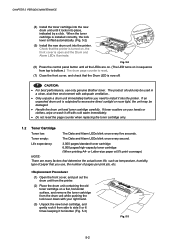
A S I C Reset Circuit CPU Core (MB86833) BUS INT Oscillator (33.33MHz) Program + Font ROM 1.0 Mbytes Address Decoder DRAM Control RAM (2.0 Mbytes) Timer FIFO Option RAM (SIMM) (max.32Mbytes) (HL-1440 only) CDCC Parallel I/O USB I/O (HL-1440 only) To PC To PC EEPROM (128 8 bits) Soft Support EEPROM I/O Engine Control I/O To Engine PCB Fig. 3-4 3-4 CHAPTER 3 THEORY OF OPERATION 1.2 Main PCB Block Diagram HL-1230/1440 Fig. 3-4 shows the block diagram of the main PCB of the HL-1230/1440 printer.
A S I C Reset Circuit CPU Core (MB86833) BUS INT Oscillator (33.33MHz) Program + Font ROM 1.0 Mbytes Address Decoder DRAM Control RAM (2.0 Mbytes) Timer FIFO Option RAM (SIMM) (max.32Mbytes) (HL-1440 only) CDCC Parallel I/O USB I/O (HL-1440 only) To PC To PC EEPROM (128 8 bits) Soft Support EEPROM I/O Engine Control I/O To Engine PCB Fig. 3-4 3-4 CHAPTER 3 THEORY OF OPERATION 1.2 Main PCB Block Diagram HL-1230/1440 Fig. 3-4 shows the block diagram of the main PCB of the HL-1230/1440 printer.

Service Manual
Page 55
CHAPTER 3 THEORY OF OPERATION HL-1450 Fig. 3-5 shows the block diagram of the main PCB of the HL-1450 printer. Reset Circuit CPU Core (MB86832) BUS INT A S I C Oscillator (33.33MHz) Program + Font ROM 8.0 Mbytes RAM (4.0 Mbytes) Option RAM (SIMM) (max. 32Mbytes) Address Decoder DRAM Control Timer FIFO CDCC Parallel I/O USB I/O To PC To PC EEPROM (512 x 8 bits) Soft Support EEPROM I/O Engine Control I/O To Engine PCB Fig. 3-5 3-5
CHAPTER 3 THEORY OF OPERATION HL-1450 Fig. 3-5 shows the block diagram of the main PCB of the HL-1450 printer. Reset Circuit CPU Core (MB86832) BUS INT A S I C Oscillator (33.33MHz) Program + Font ROM 8.0 Mbytes RAM (4.0 Mbytes) Option RAM (SIMM) (max. 32Mbytes) Address Decoder DRAM Control Timer FIFO CDCC Parallel I/O USB I/O To PC To PC EEPROM (512 x 8 bits) Soft Support EEPROM I/O Engine Control I/O To Engine PCB Fig. 3-5 3-5

Service Manual
Page 56
CHAPTER 3 THEORY OF OPERATION HL-1470N Fig. 3-6 shows the block diagram of the main PCB of the HL-1470N printer. Reset Circuit CPU Core (MB86832) BUS INT A S I C Oscillator (33.33MHz) Program + Font ROM 8.0 Mbytes Flash ROM (2.0 Mbytes) RAM (4.0 Mbytes) Address Decoder DRAM Control Timer FIFO CDCC Parallel I/O Option RAM (SIMM) (max. 32Mbytes) USB I/O Soft Support To PC To PC EEPROM (8192 x 8 bits) EEPROM I/O To PC or Hub Network Board To Engine PCB Engine Control I/O PCI Bus Control Fig. 3-6 3-6
CHAPTER 3 THEORY OF OPERATION HL-1470N Fig. 3-6 shows the block diagram of the main PCB of the HL-1470N printer. Reset Circuit CPU Core (MB86832) BUS INT A S I C Oscillator (33.33MHz) Program + Font ROM 8.0 Mbytes Flash ROM (2.0 Mbytes) RAM (4.0 Mbytes) Address Decoder DRAM Control Timer FIFO CDCC Parallel I/O Option RAM (SIMM) (max. 32Mbytes) USB I/O Soft Support To PC To PC EEPROM (8192 x 8 bits) EEPROM I/O To PC or Hub Network Board To Engine PCB Engine Control I/O PCI Bus Control Fig. 3-6 3-6

Service Manual
Page 67
The reset voltage is 4.2V (typ.) and the LOW period of two-wire method with a 128 x 8 bits configuration. Fig. 3-19 HL-1470N The EEPROM is X24C32 type of two-wire method with a 8192 x 8 bits configuration. Fig. 3-20 1.3.8 Reset circuit HL-1230/1440 The reset IC is a RN5VD42A. Fig. 3-18 HL-1450 The EEPROM is X24C04 type of two-wire method with a 512 x 8 bits configuration. CHAPTER 3 THEORY OF OPERATION 1.3.7 EEPROM HL-1230/1440 The EEPROM is X24C01A type of reset is 80ms (typ.) Fig. 3-21 3-17
The reset voltage is 4.2V (typ.) and the LOW period of two-wire method with a 128 x 8 bits configuration. Fig. 3-19 HL-1470N The EEPROM is X24C32 type of two-wire method with a 8192 x 8 bits configuration. Fig. 3-20 1.3.8 Reset circuit HL-1230/1440 The reset IC is a RN5VD42A. Fig. 3-18 HL-1450 The EEPROM is X24C04 type of two-wire method with a 512 x 8 bits configuration. CHAPTER 3 THEORY OF OPERATION 1.3.7 EEPROM HL-1230/1440 The EEPROM is X24C01A type of reset is 80ms (typ.) Fig. 3-21 3-17

Service Manual
Page 68
Fig. 3-24 3-18 CHAPTER 3 THEORY OF OPERATION HL-1450/1470N The reset IC is 80ms (typ.) Fig. 3-22 1.3.9 Engine I/O HL-1230/1440 Fig. 3-22 shows the engine interface circuit. Fig. 3-23 HL-1450/1470N Fig. 3-23 shows the engine interface circuit. The interface with the engine PCB is by fullduplex synchronous serial method. The interface with the engine PCB is by fullduplex synchronous serial method. The reset voltage is 4.2V (typ.) and the LOW period of reset is a RN5VD42A.
Fig. 3-24 3-18 CHAPTER 3 THEORY OF OPERATION HL-1450/1470N The reset IC is 80ms (typ.) Fig. 3-22 1.3.9 Engine I/O HL-1230/1440 Fig. 3-22 shows the engine interface circuit. Fig. 3-23 HL-1450/1470N Fig. 3-23 shows the engine interface circuit. The interface with the engine PCB is by fullduplex synchronous serial method. The interface with the engine PCB is by fullduplex synchronous serial method. The reset voltage is 4.2V (typ.) and the LOW period of reset is a RN5VD42A.
Service Manual
Page 134
... off . ! CAUTION: • For best performance, use , the number of paper that the printer is turned on in a clean, dust-free environment with cold water immediately. • Do not reset the page counter when replacing the toner cartridge only. 1.2 Toner Cartridge Toner low: The Data and Alarm...second. Life expectancy: 3,000 pages/standard toner cartridge 6,000 pages/high-capacity toner cartridge (When printing A4- Check that you use only genuine Brother toner. or Letter-size paper at 5% print coverage) NOTE: There are on. (The LED turns on , the front cover is open ...
... off . ! CAUTION: • For best performance, use , the number of paper that the printer is turned on in a clean, dust-free environment with cold water immediately. • Do not reset the page counter when replacing the toner cartridge only. 1.2 Toner Cartridge Toner low: The Data and Alarm...second. Life expectancy: 3,000 pages/standard toner cartridge 6,000 pages/high-capacity toner cartridge (When printing A4- Check that you use only genuine Brother toner. or Letter-size paper at 5% print coverage) NOTE: There are on. (The LED turns on , the front cover is open ...

Service Manual
Page 209
Information Conditions Drum unit change When drum unit life is 100 pages or more, and the drum counter is reset. (Maximum counter: 63) Toner cartridge change When the toner cartridge is replaced after a Toner Empty error is counted under the conditions below; APPENDIX Note that each maintenance information is stored in NVRAM, then warming-up completes without a Toner Empty or Toner Low error being detected. (Maximum counter: 27) Paper jam When a paper jam occurs. (Maximum counter: 2047) A-11
Information Conditions Drum unit change When drum unit life is 100 pages or more, and the drum counter is reset. (Maximum counter: 63) Toner cartridge change When the toner cartridge is replaced after a Toner Empty error is counted under the conditions below; APPENDIX Note that each maintenance information is stored in NVRAM, then warming-up completes without a Toner Empty or Toner Low error being detected. (Maximum counter: 27) Paper jam When a paper jam occurs. (Maximum counter: 2047) A-11


