
Users Manual - English
Page 95
.... The paper is on again. The toner cartridge or the drum Re-install the toner cartridge or the drum unit unit and toner cartridge assembly and toner cartridge assembly. several minutes, then reconnect it on . Turn off , wait a few does not rise at a specified seconds, and then turn it ...is jammed in the duplex tray. (See Paper jams on page 86.) tray of the machine. The paper tray is too hot. The fuser unit is not completely Close the paper tray properly. machine for problem. Leave the temperature within specified time. The paper is not properly loaded...
.... The paper is on again. The toner cartridge or the drum Re-install the toner cartridge or the drum unit unit and toner cartridge assembly and toner cartridge assembly. several minutes, then reconnect it on . Turn off , wait a few does not rise at a specified seconds, and then turn it ...is jammed in the duplex tray. (See Paper jams on page 86.) tray of the machine. The paper tray is too hot. The fuser unit is not completely Close the paper tray properly. machine for problem. Leave the temperature within specified time. The paper is not properly loaded...

Users Manual - English
Page 104
...tabs at the back of the machine C a Press the front cover release button and open the fuser cover (1). 1 b Slowly take out the drum unit and toner cartridge assembly. clean, flat surface with a sheet of the fuser unit. c Open the back cover (back output tray). h Close the front cover. 91 ...Put the drum unit and toner cartridge assembly back in case you accidentally spill or scatter toner. Paper is jammed at the left and right hand sides toward you place the drum unit and toner cartridge assembly on a (back output tray). f Close the fuser cover and back cover IMPORTANT We recommend...
...tabs at the back of the machine C a Press the front cover release button and open the fuser cover (1). 1 b Slowly take out the drum unit and toner cartridge assembly. clean, flat surface with a sheet of the fuser unit. c Open the back cover (back output tray). h Close the front cover. 91 ...Put the drum unit and toner cartridge assembly back in case you accidentally spill or scatter toner. Paper is jammed at the left and right hand sides toward you place the drum unit and toner cartridge assembly on a (back output tray). f Close the fuser cover and back cover IMPORTANT We recommend...
Service Manual
Page 113
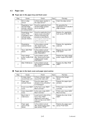
...ASSY fitted correctly. attached to each pinch roller of top cover ASSY properly? Registration front Does the registration front Re-assemble the actuator/edge actuator/edge actuator actuator catching move smoothly? on edge sensor Is there paper powder in the edge sensor... solenoid failure Is the problem solved after replacing the registration solenoid? Outer chute ASSY Is the outer chute ASSY loose fitted correctly? Fuser cover ASSY Is the fuser cover ASSY loose fitted correctly? 4.3 Paper Jam ■ Paper jam in the paper tray and front cover Step 1 2 3...
...ASSY fitted correctly. attached to each pinch roller of top cover ASSY properly? Registration front Does the registration front Re-assemble the actuator/edge actuator/edge actuator actuator catching move smoothly? on edge sensor Is there paper powder in the edge sensor... solenoid failure Is the problem solved after replacing the registration solenoid? Outer chute ASSY Is the outer chute ASSY loose fitted correctly? Fuser cover ASSY Is the fuser cover ASSY loose fitted correctly? 4.3 Paper Jam ■ Paper jam in the paper tray and front cover Step 1 2 3...

Service Manual
Page 184
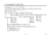
(30) Catch the Pins of the Outer chute onto the Back cover, and close the Back cover. 30b Pin Back cover Pin Outer chute ASSY 30a Back cover Fig. 4-44 Set the following parts after assembling. • Set the DX feed ASSY or DX blank cover. • Install the Drum/toner ASSY into the Printer. • Put the Paper into the Paper tray. • Reset the count of the Fuser unit and Laser unit after part replacement. (Refer to "5.1 Resetting the Periodical Replacement Parts Life" in Chapter7.) 4-29 Confidential
(30) Catch the Pins of the Outer chute onto the Back cover, and close the Back cover. 30b Pin Back cover Pin Outer chute ASSY 30a Back cover Fig. 4-44 Set the following parts after assembling. • Set the DX feed ASSY or DX blank cover. • Install the Drum/toner ASSY into the Printer. • Put the Paper into the Paper tray. • Reset the count of the Fuser unit and Laser unit after part replacement. (Refer to "5.1 Resetting the Periodical Replacement Parts Life" in Chapter7.) 4-29 Confidential
Service Manual
Page 229
8. DISASSEMBLY FLOW CHART Basic Operation 5s / 5s 5s / 5s AC Cord Drum/ Toner ASSY Disassembly / Re-Assembly (sec.) 5s / 5s DX Feed ASSY 10s / 10s Paper Tray 8.2 5s / 5s Back Cover 8.3 20s / 10s Outer Chute ASSY 8.4 15s / 20s Fuser Unit 8.5 15s / 15s Tray MP ASSY 8.7 35s / 40s Access Cover/ Side Cover L 8.9 30s / 35s...
8. DISASSEMBLY FLOW CHART Basic Operation 5s / 5s 5s / 5s AC Cord Drum/ Toner ASSY Disassembly / Re-Assembly (sec.) 5s / 5s DX Feed ASSY 10s / 10s Paper Tray 8.2 5s / 5s Back Cover 8.3 20s / 10s Outer Chute ASSY 8.4 15s / 20s Fuser Unit 8.5 15s / 15s Tray MP ASSY 8.7 35s / 40s Access Cover/ Side Cover L 8.9 30s / 35s...
Service Manual
Page 241
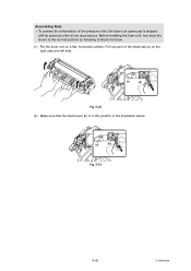
Pull up each of the pressure roller, the fuser unit spare part is in the position in the illustration below . (1) Put the fuser unit on the right side and left side. (a) (b) Fig. 5-22 (2) Make sure that the black lever (b) is shipped with its pressure roller at low nip pressure. Before installing the fuser unit, turn back the levers to the normal position by following instructions below . (a) (b) Fig. 5-23 5-41 Confidential Assembling Note: • To prevent the deformation of the black tab (a) on a flat, horizontal surface.
Pull up each of the pressure roller, the fuser unit spare part is in the position in the illustration below . (1) Put the fuser unit on the right side and left side. (a) (b) Fig. 5-22 (2) Make sure that the black lever (b) is shipped with its pressure roller at low nip pressure. Before installing the fuser unit, turn back the levers to the normal position by following instructions below . (a) (b) Fig. 5-23 5-41 Confidential Assembling Note: • To prevent the deformation of the black tab (a) on a flat, horizontal surface.
Service Manual
Page 327
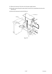
(11) Remove the harness of the fuser unit and power supply harness. (12) Put each harness through the space where the fan 60 unit is assembled and remove the PS PCB unit. (13) Remove the harness from the PS PCB unit. Harness PS PCB unit 12 11 Fig. 5-171 5-127 Confidential
(11) Remove the harness of the fuser unit and power supply harness. (12) Put each harness through the space where the fan 60 unit is assembled and remove the PS PCB unit. (13) Remove the harness from the PS PCB unit. Harness PS PCB unit 12 11 Fig. 5-171 5-127 Confidential

Service Manual
Page 518
... MP N/A NC* PF PP gear ppm PU RAM REGI SB Automatic Private IP Addressing Application Specific Integrated Circuit Assembly Connector Central Processing Unit decibel Development Dual Inline Memory Module dots per inch Duplex Electronically Erasable and Programmable Read Only Memory Feed... Roller Fuser Hexadecimal Humidity High Voltage High Voltage Power Supply Institute of Electrical and Electronic Engineers 1284 Interface Internet Protocol Version 4 Internet...
... MP N/A NC* PF PP gear ppm PU RAM REGI SB Automatic Private IP Addressing Application Specific Integrated Circuit Assembly Connector Central Processing Unit decibel Development Dual Inline Memory Module dots per inch Duplex Electronically Erasable and Programmable Read Only Memory Feed... Roller Fuser Hexadecimal Humidity High Voltage High Voltage Power Supply Institute of Electrical and Electronic Engineers 1284 Interface Internet Protocol Version 4 Internet...


