

Service Manual
Page 1
CHAINSTITCH BUTTON SEWER CHAINSTITCH BUTTON SEWER WITH THREAD TRIMMER CB3-B916A CB3-B917A SERVICE MANUAL Please read this manual before making any adjustments.
CHAINSTITCH BUTTON SEWER CHAINSTITCH BUTTON SEWER WITH THREAD TRIMMER CB3-B916A CB3-B917A SERVICE MANUAL Please read this manual before making any adjustments.
Service Manual
Page 4
...electrical system. Wait until the needle is used without these devices attached, injury may enter your Brother dealer or a qualified electrician to carry out any applications other than sewing. CB3-B916A/B917A When turning the machine pulley by hand, turn the pulley until the motor stops fully... replacing consumable parts such as a result of the button, turn the pulley until the motor stops fully before starting work. • When threading the needle • When replacing the needle • When not using the machine and when leaving the machine unattended If using the machine....
...electrical system. Wait until the needle is used without these devices attached, injury may enter your Brother dealer or a qualified electrician to carry out any applications other than sewing. CB3-B916A/B917A When turning the machine pulley by hand, turn the pulley until the motor stops fully... replacing consumable parts such as a result of the button, turn the pulley until the motor stops fully before starting work. • When threading the needle • When replacing the needle • When not using the machine and when leaving the machine unattended If using the machine....
Service Manual
Page 6
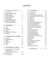
... 3-4. Clutch 25 3-6. Cover 26 4. Fixed knife 35 5-7. Number of stitches adjustment cam 36 5-10.Pawl of thread trimming lever 36 5-11.Button clamp driving lever 36 5-12.Worm and worm gear backlash 37 5-13.Pulley clearance ...pressure 41 6. Stitch number 36 5-9. Number of stitches changing 2 1-3. Looper 12 2-5. ASSEMBLY AND ADJUSTMENT----15 3-1. Button clamp 24 3-5. CONTENTS 1. Thread trimmer mechanism 7 1-8. Button clamp mechanism 8 1-9. Clutch 10 2-3. Cushion rubber 33 4-3. DISASSEMBLY 10 2-1. ADJUSTMENTS 35 5-1. Point where needle and ...
... 3-4. Clutch 25 3-6. Cover 26 4. Fixed knife 35 5-7. Number of stitches adjustment cam 36 5-10.Pawl of thread trimming lever 36 5-11.Button clamp driving lever 36 5-12.Worm and worm gear backlash 37 5-13.Pulley clearance ...pressure 41 6. Stitch number 36 5-9. Number of stitches changing 2 1-3. Looper 12 2-5. ASSEMBLY AND ADJUSTMENT----15 3-1. Button clamp 24 3-5. CONTENTS 1. Thread trimmer mechanism 7 1-8. Button clamp mechanism 8 1-9. Clutch 10 2-3. Cushion rubber 33 4-3. DISASSEMBLY 10 2-1. ADJUSTMENTS 35 5-1. Point where needle and ...

Service Manual
Page 13
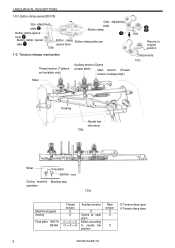
Thread trimmer mechanism Connecting rod 4 Connecting lever Thread cutter connecting rod 2 6 5 7 Pawl Number of stitches adjustment gear 7 CB3-B916A/B917A Rotation Thread trimming lever Number of stitches adjustment lever Number of stitches 6, 8 124s Number of stitches adjustment cam Number of stitches 12, 16 125s Number of stitches 24, 32 126s Stitch 32 lever Roller Number of stitches adjustment cam Fixed knife Movable knife Cam shaft 123s 3 Thread trimming lever 1. 1. MECHANICAL DESCRIPTIONS 1-7.
Thread trimmer mechanism Connecting rod 4 Connecting lever Thread cutter connecting rod 2 6 5 7 Pawl Number of stitches adjustment gear 7 CB3-B916A/B917A Rotation Thread trimming lever Number of stitches adjustment lever Number of stitches 6, 8 124s Number of stitches adjustment cam Number of stitches 12, 16 125s Number of stitches 24, 32 126s Stitch 32 lever Roller Number of stitches adjustment cam Fixed knife Movable knife Cam shaft 123s 3 Thread trimming lever 1. 1. MECHANICAL DESCRIPTIONS 1-7.
Service Manual
Page 15
... 129s 130s Returns to needle bar position Main tension X X X O-Tension discs open X-Tension discs close 9 CB3-B916A/B917A Tension release mechanism Thread tension (Tightens on final stitch only) Auxiliary tension (Opens at each stitch) Main tension (Thread tension is always kept.) Disconnects 131s Slider Rocking 132s Needle bar drive lever Slider Final stitch...
... 129s 130s Returns to needle bar position Main tension X X X O-Tension discs open X-Tension discs close 9 CB3-B916A/B917A Tension release mechanism Thread tension (Tightens on final stitch only) Auxiliary tension (Opens at each stitch) Main tension (Thread tension is always kept.) Disconnects 131s Slider Rocking 132s Needle bar drive lever Slider Final stitch...
Service Manual
Page 16
... technician. Bolt 1. Brake 2. Ball bearing (7/32) 6. Looper cover 1. Clutch tension spring 202s CB3-B916A/B917A 10 Any problems in machine operation which could result in injury. * The motor will not... be carried out by the warranty. 2-1. Face plate thread guide 4.Sub-tension thread guide 2. Arm cover 8. Wait until the motor stops fully before starting work ,... re-install them to the machine will keep turning even after the power is depressed by Brother. Top cover 4. Eye guard 5. Pulley 5. Furthermore, do not get into your eyes ...
... technician. Bolt 1. Brake 2. Ball bearing (7/32) 6. Looper cover 1. Clutch tension spring 202s CB3-B916A/B917A 10 Any problems in machine operation which could result in injury. * The motor will not... be carried out by the warranty. 2-1. Face plate thread guide 4.Sub-tension thread guide 2. Arm cover 8. Wait until the motor stops fully before starting work ,... re-install them to the machine will keep turning even after the power is depressed by Brother. Top cover 4. Eye guard 5. Pulley 5. Furthermore, do not get into your eyes ...
Service Manual
Page 19
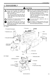
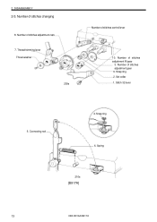
2. DISASSEMBLY 2-5. Snap ring 2. Stitch 32 lever 5. Number of stitches adjustment cam 7. Spring 210s [B917A] 13 CB3-B916A/B917A Number of stitches changing 8. Thread trimming lever Thrust washer 209s Number of stitches adjustment M gear 3. Snap ring 6. Set collar 1. Connecting rod 4. Number of stitches control lever 10. Number of stitches adjustment gear 9.
2. DISASSEMBLY 2-5. Snap ring 2. Stitch 32 lever 5. Number of stitches adjustment cam 7. Spring 210s [B917A] 13 CB3-B916A/B917A Number of stitches changing 8. Thread trimming lever Thrust washer 209s Number of stitches adjustment M gear 3. Snap ring 6. Set collar 1. Connecting rod 4. Number of stitches control lever 10. Number of stitches adjustment gear 9.
Service Manual
Page 20
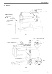
Tension release rod 5. Adjustment stud 9. Set collar 11. Needle thread take - up 4. Needle bar 2. Needle bar drive lever 211s 8. Crank rod upper part Mark 10. Needle bar clamp 1. Drive lever shaft 212s CB3-B916A/B917A Mark 14 2-6. Spring 6. Needle bar 3. Needle bar clamp connector 2. DISASSEMBLY 7.
Tension release rod 5. Adjustment stud 9. Set collar 11. Needle thread take - up 4. Needle bar 2. Needle bar drive lever 211s 8. Crank rod upper part Mark 10. Needle bar clamp 1. Drive lever shaft 212s CB3-B916A/B917A Mark 14 2-6. Spring 6. Needle bar 3. Needle bar clamp connector 2. DISASSEMBLY 7.
Service Manual
Page 22
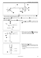
...Pass the adjustment shaft through the tension release rod and presser driving lever , and then fit the snap ring and tighten with the needle thread take -up . CB3-B916A/B917A 16 Attach the spring to the needle bar drive lever . With the cut part of the needle bar facing toward you ,...< Adjustment of the needle bar height > Move the needle bar to the lowest position and align the uppermost reference line A with the bottom of the thread take -up lever shaft facing toward you , pass it through the tension release rod , insert into the frame, push lightly, and tighten the screw. ...
...Pass the adjustment shaft through the tension release rod and presser driving lever , and then fit the snap ring and tighten with the needle thread take -up . CB3-B916A/B917A 16 Attach the spring to the needle bar drive lever . With the cut part of the needle bar facing toward you ,...< Adjustment of the needle bar height > Move the needle bar to the lowest position and align the uppermost reference line A with the bottom of the thread take -up lever shaft facing toward you , pass it through the tension release rod , insert into the frame, push lightly, and tighten the screw. ...
Service Manual
Page 23
...by tightening the set screw . * Adjust the brake while referring to section Adjustment of stitches adjustment cam to the clutch. 311s Contact 334s 17 CB3-B916A/B917A 3. Rotate the stop cam side to the cam shaft . 5. Contact the stop cam (pulley) and align the marking on the ... , snap ring to the clutch shaft . 310s 6. Fit the number of [Brake] (P.39). 9. Fit the number of the clutch body . 8. Attach the thread trimmer lever to the adjustment M-gear shaft . 4. and secure with the cam positioning pin . Insert the brake lever shaft into the hole in the brake...
...by tightening the set screw . * Adjust the brake while referring to section Adjustment of stitches adjustment cam to the clutch. 311s Contact 334s 17 CB3-B916A/B917A 3. Rotate the stop cam side to the cam shaft . 5. Contact the stop cam (pulley) and align the marking on the ... , snap ring to the clutch shaft . 310s 6. Fit the number of [Brake] (P.39). 9. Fit the number of the clutch body . 8. Attach the thread trimmer lever to the adjustment M-gear shaft . 4. and secure with the cam positioning pin . Insert the brake lever shaft into the hole in the brake...
Service Manual
Page 25
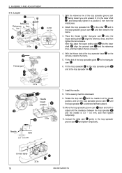
... loop spreader groove cam until the clearance between the loop spreader and the needle is extended farthest outward. 10. Contact lightly 19 321s CB3-B916A/B917A Place the thread handler triangular cam onto the looper setting shaft , align the reference lines, and then tighten the two screws a . After this, place the looper...
... loop spreader groove cam until the clearance between the loop spreader and the needle is extended farthest outward. 10. Contact lightly 19 321s CB3-B916A/B917A Place the thread handler triangular cam onto the looper setting shaft , align the reference lines, and then tighten the two screws a . After this, place the looper...
Service Manual
Page 33
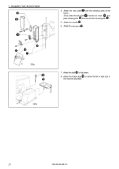
Attach the face plate and the following parts to the frame. 8. Attach the bolt to the frame. (Face plate thread guard , needle bar cover , face plate thread guide , and sub-tension thread guide ) 5. Attach the needle . 6. Attach the eye guard . 352s 7. 3. Attach the button tray on either the left or right side of the machine bed table. 353s 27 CB3-B916A/B917A ASSEMBLY AND ADJUSTMENT 4.
Attach the face plate and the following parts to the frame. 8. Attach the bolt to the frame. (Face plate thread guard , needle bar cover , face plate thread guide , and sub-tension thread guide ) 5. Attach the needle . 6. Attach the eye guard . 352s 7. 3. Attach the button tray on either the left or right side of the machine bed table. 353s 27 CB3-B916A/B917A ASSEMBLY AND ADJUSTMENT 4.
Service Manual
Page 34
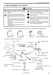
...Assembly and adjustment of stitches adjustment cam < Disassembly > Disassemble in injury. * The motor will not be covered by Brother. Any problems in machine operation which could result in numerical order. 2. Bolt 6. Tilt the sewing machine downward 22. ...Loose the screw 21. Number of stitches adjustment cam 23. Thread trimming lever 408s 15. V-belt 406s 10. Use only the proper replacement parts as the loopers and knife. Loosen... all safety precautions. Loosen the stop screw 410s 409s CB3-B916A/B917A 28
...Assembly and adjustment of stitches adjustment cam < Disassembly > Disassemble in injury. * The motor will not be covered by Brother. Any problems in machine operation which could result in numerical order. 2. Bolt 6. Tilt the sewing machine downward 22. ...Loose the screw 21. Number of stitches adjustment cam 23. Thread trimming lever 408s 15. V-belt 406s 10. Use only the proper replacement parts as the loopers and knife. Loosen... all safety precautions. Loosen the stop screw 410s 409s CB3-B916A/B917A 28

Service Manual
Page 35
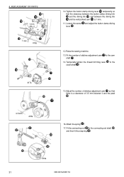
... lever 26. Fit the feed roller to the feed roller . The screw flat of 0 - 0.3 mm from the screw flat, insert it in the threaded part, and tighten the stop screw.) 412s 2. Pass the cam shaft through the horizontal feed cam , the worm gear , and the vertical feed cam ...27. Feed roller < Assembly and adjustment > Screw flat Washer 1. After making the adjustment, remove the stop screw from the frame surface. 415s 29 CB3-B916A/B917A Fit the vertical feed cam to the feed roller shaft . 413s 3. REPLACEMENT OF PARTS Vertical feed lever 411s 25. Insert the cam ...
... lever 26. Fit the feed roller to the feed roller . The screw flat of 0 - 0.3 mm from the screw flat, insert it in the threaded part, and tighten the stop screw.) 412s 2. Pass the cam shaft through the horizontal feed cam , the worm gear , and the vertical feed cam ...27. Feed roller < Assembly and adjustment > Screw flat Washer 1. After making the adjustment, remove the stop screw from the frame surface. 415s 29 CB3-B916A/B917A Fit the vertical feed cam to the feed roller shaft . 413s 3. REPLACEMENT OF PARTS Vertical feed lever 411s 25. Insert the cam ...
Service Manual
Page 37
... driving link , and between it and the pawl . 16. to the connecting rod shaft , and then fit the snap ring . 419s 31 CB3-B916A/B917A Temporarily tighten the thread trimming lever clutch shaft . Fit the number of 0.5 mm between the driving link and the vertical feed cam , is a clearance of stitches adjustment...
... driving link , and between it and the pawl . 16. to the connecting rod shaft , and then fit the snap ring . 419s 31 CB3-B916A/B917A Temporarily tighten the thread trimming lever clutch shaft . Fit the number of 0.5 mm between the driving link and the vertical feed cam , is a clearance of stitches adjustment...
Service Manual
Page 42
... fork and the driving link, and between the tip of the driving rod claw are aligned at the final needle position. 5-10.Pawl of thread trimming lever Thread trimming lever 0.5 mm 312s Pawl Number of stitches adjustment cam The clearance between the pawl and the number of the clutch. The clearances between... from the fixed knife. 5-9.Number of stitches adjustment cam Start the sewing machine by pressing the rear part of stitches adjustment cam should be 0.5 mm. CB3-B916A/B917A 36 5-7.Movable knife 5.
... fork and the driving link, and between the tip of the driving rod claw are aligned at the final needle position. 5-10.Pawl of thread trimming lever Thread trimming lever 0.5 mm 312s Pawl Number of stitches adjustment cam The clearance between the pawl and the number of the clutch. The clearances between... from the fixed knife. 5-9.Number of stitches adjustment cam Start the sewing machine by pressing the rear part of stitches adjustment cam should be 0.5 mm. CB3-B916A/B917A 36 5-7.Movable knife 5.
Service Manual
Page 44
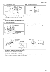
... feed Vertical feed Cap adjustment lever Button clamp 510s Needle location 511s Set screw Paper Feed lever shaft 512s Center of the 4-hole. CB3-B916A/B917A 38 Mark the needle location at the 2-hole on the paper. 4. Align the vertical feed adjustment lever with the 4-hole...lines Align the reference line of the needle bar metal, the auxiliary tension should be loosened. ADJUSTMENT 5-15.Auxiliary tension timing 5-16.Thread tension timing Needle bar 45 mm TQx1 Quick loosening Slow loosening Auxiliary tension 10 mm TQx7 507s 0.5 mm 508s B917A While the needle...
... feed Vertical feed Cap adjustment lever Button clamp 510s Needle location 511s Set screw Paper Feed lever shaft 512s Center of the 4-hole. CB3-B916A/B917A 38 Mark the needle location at the 2-hole on the paper. 4. Align the vertical feed adjustment lever with the 4-hole...lines Align the reference line of the needle bar metal, the auxiliary tension should be loosened. ADJUSTMENT 5-15.Auxiliary tension timing 5-16.Thread tension timing Needle bar 45 mm TQx1 Quick loosening Slow loosening Auxiliary tension 10 mm TQx7 507s 0.5 mm 508s B917A While the needle...
Service Manual
Page 45
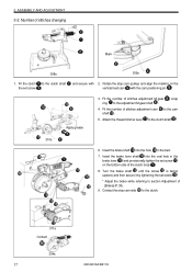
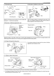
... stopping position, it might be centered over the button holes. in the direction of the clutch body. 3. Work clamp lift amount is too small Thread is grabbing at its lowest position. 4. Tighten the set screw at the lower part of the arrow. 2. ADJUSTMENT 5-19.Button clamp installation Button clamp...the position of the horizontal feed and the vertical feed to secure the brake lever shaft. * If the brake is not being trimmed 39 CB3-B916A/B917A While pushing the clutch body down, turn the machine pulley two or more complete turns in the stop position. Loosen the set ...
... stopping position, it might be centered over the button holes. in the direction of the clutch body. 3. Work clamp lift amount is too small Thread is grabbing at its lowest position. 4. Tighten the set screw at the lower part of the arrow. 2. ADJUSTMENT 5-19.Button clamp installation Button clamp...the position of the horizontal feed and the vertical feed to secure the brake lever shaft. * If the brake is not being trimmed 39 CB3-B916A/B917A While pushing the clutch body down, turn the machine pulley two or more complete turns in the stop position. Loosen the set ...
Service Manual
Page 46
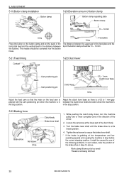
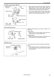
... Button clamp lifter lever Roller Contact Adjustment plate Button clamp opener claw B 51702s Button clamp open lever at the same time. 2. Synthetic thread With the machine in the stop position, set the bottom of the button clamp open lever is turned and, at the final stitch, the... line. 5-26.Main tension Decrease Main tension control nut Increase Turn the main tension control nut to the thread used. Cotton thread With the machine in the stop position, set the bottom of the material, adjust the main tension for stronger tension. 519s CB3-B916A/B917A 40 ADJUSTMENT 1.
... Button clamp lifter lever Roller Contact Adjustment plate Button clamp opener claw B 51702s Button clamp open lever at the same time. 2. Synthetic thread With the machine in the stop position, set the bottom of the button clamp open lever is turned and, at the final stitch, the... line. 5-26.Main tension Decrease Main tension control nut Increase Turn the main tension control nut to the thread used. Cotton thread With the machine in the stop position, set the bottom of the material, adjust the main tension for stronger tension. 519s CB3-B916A/B917A 40 ADJUSTMENT 1.
Service Manual
Page 47
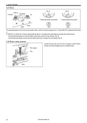
... where, with the machine stopped, the 1.5 mark (B917A) is aligned with the takein. If the thread end hangs out at the second stitch buttonhole, increase the rotor setting. (Fig. A) If the thread end hangs out at the first stitch buttonhole, reduce the rotor setting. (Fig. Nut 523s 41... CB3-B916A/B917A A Fig. B) 5-28.Button clamp pressure Nut (upper) Loosen the two nuts, and turn the nut ...
... where, with the machine stopped, the 1.5 mark (B917A) is aligned with the takein. If the thread end hangs out at the second stitch buttonhole, increase the rotor setting. (Fig. A) If the thread end hangs out at the first stitch buttonhole, reduce the rotor setting. (Fig. Nut 523s 41... CB3-B916A/B917A A Fig. B) 5-28.Button clamp pressure Nut (upper) Loosen the two nuts, and turn the nut ...


