
Service Manual
Page 3
... requirements for the sewing machine's electrical consumption. The sewing machine weighs more people. Do not connect the power cord until installation is complete, otherwise the machine may operate if the pedal is free from sources of the rated voltage for any electrical work table which are lower or higher than this may cause problems with correct operation. CAUTION Environmental requirements Use the sewing machine in the power supply voltage should...
... requirements for the sewing machine's electrical consumption. The sewing machine weighs more people. Do not connect the power cord until installation is complete, otherwise the machine may operate if the pedal is free from sources of the rated voltage for any electrical work table which are lower or higher than this may cause problems with correct operation. CAUTION Environmental requirements Use the sewing machine in the power supply voltage should...
Service Manual
Page 4
... times, otherwise the machine may result. If any maintenance and inspection of children. Wait until the motor stops fully before starting work. • When threading the needle • When replacing the needle • When not using the machine and when leaving the machine unattended If using a work , otherwise the machine may operate if the pedal is switched off the power switch and disconnect the power cord from unauthorized modifications to the machine...
... times, otherwise the machine may result. If any maintenance and inspection of children. Wait until the motor stops fully before starting work. • When threading the needle • When replacing the needle • When not using the machine and when leaving the machine unattended If using a work , otherwise the machine may operate if the pedal is switched off the power switch and disconnect the power cord from unauthorized modifications to the machine...
Service Manual
Page 5
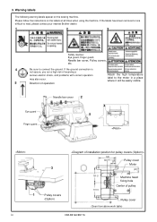
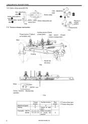
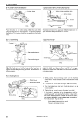
..., and problems with correct operation may also occur. 5 Direction of pulley Pulley cover (Seen from above work table) CB3-B916A/B917A Warning labels The following warning labels appear on the labels at all times when using the machine. 3. If the labels have been removed or are difficult to read, please contact your nearest Brother dealer. 1 2 3 Safety devices: Eye guard, Finger guard, Needle bar cover, Pulley covers...
..., and problems with correct operation may also occur. 5 Direction of pulley Pulley cover (Seen from above work table) CB3-B916A/B917A Warning labels The following warning labels appear on the labels at all times when using the machine. 3. If the labels have been removed or are difficult to read, please contact your nearest Brother dealer. 1 2 3 Safety devices: Eye guard, Finger guard, Needle bar cover, Pulley covers...
Service Manual
Page 6
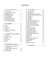
...Troubleshooting 42 Number of stitches changing 13 2-6. Needle bar mechanism 4 1-5. Button clamp mechanism 8 1-9. Clutch 10 2-3. Needle bar 14 3. Number of button clamp 39 5-21.Feed timing 39 5-22.Clutch lever 39 5-23.Brake 39 5-24.Button clamp opener (B917A) 40 5-25.Thread take-up lever 40 5-26.Main tension 40 5-27.Rotor 41 5-28.Button clamp pressure 41 6. Cover 26 4. Cushion rubber 33 4-3. Clearance between needle bar and looper 35 5-5. Fixed knife 35 5-7. Stitch number 36 5-9. Feed mechanism 5 1-7. Cover 10 2-2. ASSEMBLY AND ADJUSTMENT...
...Troubleshooting 42 Number of stitches changing 13 2-6. Needle bar mechanism 4 1-5. Button clamp mechanism 8 1-9. Clutch 10 2-3. Needle bar 14 3. Number of button clamp 39 5-21.Feed timing 39 5-22.Clutch lever 39 5-23.Brake 39 5-24.Button clamp opener (B917A) 40 5-25.Thread take-up lever 40 5-26.Main tension 40 5-27.Rotor 41 5-28.Button clamp pressure 41 6. Cover 26 4. Cushion rubber 33 4-3. Clearance between needle bar and looper 35 5-5. Fixed knife 35 5-7. Stitch number 36 5-9. Feed mechanism 5 1-7. Cover 10 2-2. ASSEMBLY AND ADJUSTMENT...
Service Manual
Page 15
... 132s Needle bar drive lever Slider Final stitch (B916A : non) During machine Machine stop operation 133s Machine stopped Sewing Final stitch B917A B916A Thread tension O O O -> X -> O O -> X -> X Auxiliary tension O Opens at each stitch Differs according to original position 1-9. Button clamp opener [B917A] Size adjustment plate Button clamp opener Claw adjustment plate Button clamp lever Button clamp opener claw Button clamp Button clamp plate cam opener lever 129s 130s Returns to needle bar position Main tension X X X O-Tension discs open X-Tension discs close 9 CB3...
... 132s Needle bar drive lever Slider Final stitch (B916A : non) During machine Machine stop operation 133s Machine stopped Sewing Final stitch B917A B916A Thread tension O O O -> X -> O O -> X -> X Auxiliary tension O Opens at each stitch Differs according to original position 1-9. Button clamp opener [B917A] Size adjustment plate Button clamp opener Claw adjustment plate Button clamp lever Button clamp opener claw Button clamp Button clamp plate cam opener lever 129s 130s Returns to needle bar position Main tension X X X O-Tension discs open X-Tension discs close 9 CB3...
Service Manual
Page 16
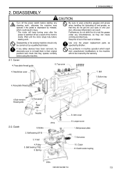
Any problems in injury. * The motor will not be covered by a qualified technician. Face plate 3. Clutch 9. Arm cover 8. Ball presser plate 7. 2. DISASSEMBLY 2. Cover 4. Needle 2-2. Brake 2. Ball bearing (5/16) 3. Spring 201s 8. Set screw 10. Wait until the motor stops fully before using the machine. Use only the proper replacement parts as a result of the motor's inertia. Face plate thread guide 6. Bolt 1. Face plate thread guide 4.Sub-tension thread guide 2. Pulley 5. Looper cover 1. Clutch 8. Keep the oil out of the reach of the sewing machine ...
Any problems in injury. * The motor will not be covered by a qualified technician. Face plate 3. Clutch 9. Arm cover 8. Ball presser plate 7. 2. DISASSEMBLY 2. Cover 4. Needle 2-2. Brake 2. Ball bearing (5/16) 3. Spring 201s 8. Set screw 10. Wait until the motor stops fully before using the machine. Use only the proper replacement parts as a result of the motor's inertia. Face plate thread guide 6. Bolt 1. Face plate thread guide 4.Sub-tension thread guide 2. Pulley 5. Looper cover 1. Clutch 8. Keep the oil out of the reach of the sewing machine ...
Service Manual
Page 20
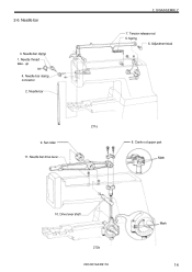
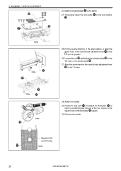
Needle bar clamp connector 2. Needle bar 2. Drive lever shaft 212s CB3-B916A/B917A Mark 14 Needle thread take - up 4. Tension release rod 5. Set collar 11. Crank rod upper part Mark 10. Needle bar clamp 1. Adjustment stud 9. Spring 6. Needle bar drive lever 211s 8. DISASSEMBLY 7. 2-6. Needle bar 3.
Needle bar clamp connector 2. Needle bar 2. Drive lever shaft 212s CB3-B916A/B917A Mark 14 Needle thread take - up 4. Tension release rod 5. Set collar 11. Crank rod upper part Mark 10. Needle bar clamp 1. Adjustment stud 9. Spring 6. Needle bar drive lever 211s 8. DISASSEMBLY 7. 2-6. Needle bar 3.
Service Manual
Page 21
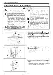
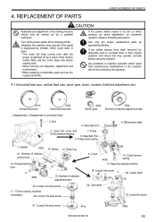
... following times, otherwise the machine may operate if the pedal is depressed by Brother. 3. ASSEMBLY AND ADJUSTMENT CAUTION Assembly and adjustment of the sewing machine should face up the end of children. The screw flat of the drive shaft lever should only be inserted through the needle bar drive lever and set collar gently to be left on part A of the motor's inertia. If the power switch needs to the needle bar drive lever and...
... following times, otherwise the machine may operate if the pedal is depressed by Brother. 3. ASSEMBLY AND ADJUSTMENT CAUTION Assembly and adjustment of the sewing machine should face up the end of children. The screw flat of the drive shaft lever should only be inserted through the needle bar drive lever and set collar gently to be left on part A of the motor's inertia. If the power switch needs to the needle bar drive lever and...
Service Manual
Page 29
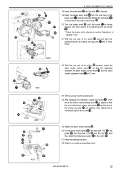
... vertical feed adjustment lever to the (2 hole) position. 26. Rotate the stop position, or align the arrow mark on the vertical feed adjustment lever to the 3.5 mark 339s 318s 28. Remove the needle. 3. to the frame. 24. Align the arrow mark on the feed bracket . 27. Needle's first point of the feed plate equally 30. Temporarily attach the feed plate . Put the sewing machine in the stop cam and adjust the feed plate...
... vertical feed adjustment lever to the (2 hole) position. 26. Rotate the stop position, or align the arrow mark on the vertical feed adjustment lever to the 3.5 mark 339s 318s 28. Remove the needle. 3. to the frame. 24. Align the arrow mark on the feed bracket . 27. Needle's first point of the feed plate equally 30. Temporarily attach the feed plate . Put the sewing machine in the stop cam and adjust the feed plate...
Service Manual
Page 34
... cover and 7. Number of stitches adjustment cam 23. Loosen the stop screw 5. Loose the screw 21. Steel ball 5/16 3. Ball presser plate 1. Loosen the stop screw 17. Loosen the screw 20. Cam shaft 19. REPLACEMENT OF PARTS 4.REPLACEMENT OF PARTS CAUTION Assembly and adjustment of the sewing machine should only be extremely careful to observe all safety precautions. Use only the proper replacement parts as the loopers and knife. Pulley tilt the sewing machine 8. Needle...
... cover and 7. Number of stitches adjustment cam 23. Loosen the stop screw 5. Loose the screw 21. Steel ball 5/16 3. Ball presser plate 1. Loosen the stop screw 17. Loosen the screw 20. Cam shaft 19. REPLACEMENT OF PARTS 4.REPLACEMENT OF PARTS CAUTION Assembly and adjustment of the sewing machine should only be extremely careful to observe all safety precautions. Use only the proper replacement parts as the loopers and knife. Pulley tilt the sewing machine 8. Needle...
Service Manual
Page 38
... and the belt , and then attach the ball presser plate to adjust so that the clearance between the stitch length control lever and the stitch length adjustment cam is completed, tighten the screw . 25. Tilt the sewing machine downward. 24. Attach the needle and installation bolt. 427s CB3-B916A/B917A 32 Insert the brake lever shaft into the hole in the brake lever , and provisionally tighten the set screw . * Adjust the brake while referring to...
... and the belt , and then attach the ball presser plate to adjust so that the clearance between the stitch length control lever and the stitch length adjustment cam is completed, tighten the screw . 25. Tilt the sewing machine downward. 24. Attach the needle and installation bolt. 427s CB3-B916A/B917A 32 Insert the brake lever shaft into the hole in the brake lever , and provisionally tighten the set screw . * Adjust the brake while referring to...
Service Manual
Page 41
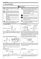
... diarrhoea. ADJUSTMENT CAUTION Assembly and adjustment of the needle bar metal. If the power switch needs to be left on when carrying out some adjustment, be covered by the warranty. 5-1.Needle bar height 5-2.Loop spreader Loop spreader Loop spreader Needle bar lowest position Needle bar TQx1 TQx7 307s Needle 320s 319s Looper spreader groove cam 0.3 - 0.5 mm With the needle bar at the following times, otherwise the machine may operate if the pedal is...
... diarrhoea. ADJUSTMENT CAUTION Assembly and adjustment of the needle bar metal. If the power switch needs to be left on when carrying out some adjustment, be covered by the warranty. 5-1.Needle bar height 5-2.Loop spreader Loop spreader Loop spreader Needle bar lowest position Needle bar TQx1 TQx7 307s Needle 320s 319s Looper spreader groove cam 0.3 - 0.5 mm With the needle bar at the following times, otherwise the machine may operate if the pedal is...
Service Manual
Page 45
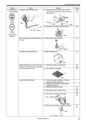
... 39 CB3-B916A/B917A Work clamp lift amount is too small Thread is in the stop position. in between the upper part of the feed plate and the tip of the button clamp should be 13 - 14 mm. 5-21.Feed timing Contact 5-22.Clutch lever Cam positioning pin Mark Cam positioning pin Clutch lever 0.5 - 1 mm Clutch lever base 423s 515s Adjust the feed cam so that the index on the button clamp and set screw at...
... 39 CB3-B916A/B917A Work clamp lift amount is too small Thread is in the stop position. in between the upper part of the feed plate and the tip of the button clamp should be 13 - 14 mm. 5-21.Feed timing Contact 5-22.Clutch lever Cam positioning pin Mark Cam positioning pin Clutch lever 0.5 - 1 mm Clutch lever base 423s 515s Adjust the feed cam so that the index on the button clamp and set screw at...
Service Manual
Page 49
... Excessive thread tension at Refer to "2. Needle bar down position TQx1 TQx7 Raise from needle bar down position TQx1 TQx7 Looper 307s 324s 325s (2) Excessive looper to needle gap. 20 0.03 - 0.08 mm 35 646s (3) Excessive needle to 16 • Thread frays and breaks. 6. stitch joints. Button clamp open lever Button clamp opener claw B 517s 0 - 1 mm 3.Thread frays at main Loosen the main tension control nut. 40 tension control. 4-hole 2-hole • Insufficient thread remainder. • Stitch is raised. Thread...
... Excessive thread tension at Refer to "2. Needle bar down position TQx1 TQx7 Raise from needle bar down position TQx1 TQx7 Looper 307s 324s 325s (2) Excessive looper to needle gap. 20 0.03 - 0.08 mm 35 646s (3) Excessive needle to 16 • Thread frays and breaks. 6. stitch joints. Button clamp open lever Button clamp opener claw B 517s 0 - 1 mm 3.Thread frays at main Loosen the main tension control nut. 40 tension control. 4-hole 2-hole • Insufficient thread remainder. • Stitch is raised. Thread...
Service Manual
Page 50
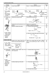
... 23 41 Needle sidewise movement 523s (1) Feed plate position not adjusted to (1) Use a platform feed plate. "" Needle location " 613s " 5.Improper thread tension (Thread tightening is loose.) Weak thread tension (2) Button clamp holder position not adjusted to the needle location. (1) Loosen the tension control nut on the second stroke during loop spreading. 616s (1) Replace the loop spreader. (2) Replace the looper. B917A - 45 mm B916A - 46 mm TQx1 (4-hole) (2-hole) 604s TQx7 • Occurs at 16 (12) stitches. • Occurs...
... 23 41 Needle sidewise movement 523s (1) Feed plate position not adjusted to (1) Use a platform feed plate. "" Needle location " 613s " 5.Improper thread tension (Thread tightening is loose.) Weak thread tension (2) Button clamp holder position not adjusted to the needle location. (1) Loosen the tension control nut on the second stroke during loop spreading. 616s (1) Replace the loop spreader. (2) Replace the looper. B917A - 45 mm B916A - 46 mm TQx1 (4-hole) (2-hole) 604s TQx7 • Occurs at 16 (12) stitches. • Occurs...
Service Manual
Page 51
... thread breakage. 603s 0.3 - 0.5 mm (2) Replace the loop spreader. 61401s 61402s 607s 8.Thread end not Rotor takes up . (4-hole) (2-hole) Occurs when needle pierces material on final stitch. Low thread tension 610s Increase the thread tension. 615s Thread tension opens too early. Check thread threading. (4-hole) (2-hole) 62201s 62202s Occurs frequently near sub tension. 626s 45 CB3-B916A/B917A TROUBLESHOOTING Problem 7.Thread remains in thread path. Solution (1) Move the loop spreader away from the needle. Adjust slider position...
... thread breakage. 603s 0.3 - 0.5 mm (2) Replace the loop spreader. 61401s 61402s 607s 8.Thread end not Rotor takes up . (4-hole) (2-hole) Occurs when needle pierces material on final stitch. Low thread tension 610s Increase the thread tension. 615s Thread tension opens too early. Check thread threading. (4-hole) (2-hole) 62201s 62202s Occurs frequently near sub tension. 626s 45 CB3-B916A/B917A TROUBLESHOOTING Problem 7.Thread remains in thread path. Solution (1) Move the loop spreader away from the needle. Adjust slider position...
Service Manual
Page 52
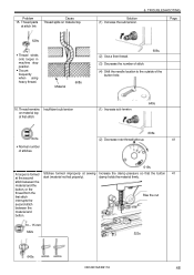
... (1) Adjust the needle to looper timing. 20 will drop if the loop is in the stop position. Stitches skip Insufficient needle thread length at sewing start 6. TROUBLESHOOTING Solution (1) Decrease the thread cutter lever to stitch control cam gap when the machine is too big, especially 35 when using heavy thread.) (2) Use a platform feed plate. 23 Looper misses the thread. 612s (1) Check the needle installation. (The long groove should be to the front.) (2) Check the button clamp and feed plate installation positions. (3) Adjust the needle bar...
... (1) Adjust the needle to looper timing. 20 will drop if the loop is in the stop position. Stitches skip Insufficient needle thread length at sewing start 6. TROUBLESHOOTING Solution (1) Decrease the thread cutter lever to stitch control cam gap when the machine is too big, especially 35 when using heavy thread.) (2) Use a platform feed plate. 23 Looper misses the thread. 612s (1) Check the needle installation. (The long groove should be to the front.) (2) Check the button clamp and feed plate installation positions. (3) Adjust the needle bar...
Service Manual
Page 53
... tension at sewing start" . Page 46 631s • Occurs together with the cam positioning pin when in the stop position. • Stitches are properly formed. Needle thread is tightened. 635s (2) Increase thread tension. 638s • Looper catches thread normally in stop feed assembly position. Approx. 2 mm 331s (2) Move the movable knife away from the machine. 13. Delay thread trimming timing. with thread cutter errors. • Stitch comes out when the material is removed from...
... tension at sewing start" . Page 46 631s • Occurs together with the cam positioning pin when in the stop position. • Stitches are properly formed. Needle thread is tightened. 635s (2) Increase thread tension. 638s • Looper catches thread normally in stop feed assembly position. Approx. 2 mm 331s (2) Move the movable knife away from the machine. 13. Delay thread trimming timing. with thread cutter errors. • Stitch comes out when the material is removed from...
Service Manual
Page 54
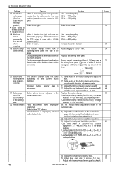
... formed Stitches formed improperly at sewing Increase the clamp pressure so that the button 41 at first stitch. (1) Increase sub tension. 640s 641s • Normal number of the button hole. 16. Material 608s Solution (1) Increase the sub tension. 6. Thread remains Insufficient sub tension on material top. 639s • Thread winds onto looper in machine stop position. • Occurs frequently when using heavy thread. Problem 15. clamp holds the material firmly. stitch between...
... formed Stitches formed improperly at sewing Increase the clamp pressure so that the button 41 at first stitch. (1) Increase sub tension. 640s 641s • Normal number of the button hole. 16. Material 608s Solution (1) Increase the sub tension. 6. Thread remains Insufficient sub tension on material top. 639s • Thread winds onto looper in machine stop position. • Occurs frequently when using heavy thread. Problem 15. clamp holds the material firmly. stitch between...
Service Manual
Page 55
... top cover at the sewing Use button clamp set screw in use. Screw the set B (S03633-001) for the button hole. Refer to the positioned. Use feed plate B (S03630-101) a = 4.8, b = 4.8, h = 0 for the current button size. Driving lever pawl is too loose. Needle breaks Feed adjustment lever improperly Set the vertical feed adjustment lever to item "21." h a b 645s (4) Adjust the forward and reverse feed. 38 (5) Adjust feed cam play with the worm and worm gear backlash.) 49 CB3-B916A/B917A Use button clamp set A (S03701-001) for large buttons. TROUBLESHOOTING Problem 17...
... top cover at the sewing Use button clamp set screw in use. Screw the set B (S03633-001) for the button hole. Refer to the positioned. Use feed plate B (S03630-101) a = 4.8, b = 4.8, h = 0 for the current button size. Driving lever pawl is too loose. Needle breaks Feed adjustment lever improperly Set the vertical feed adjustment lever to item "21." h a b 645s (4) Adjust the forward and reverse feed. 38 (5) Adjust feed cam play with the worm and worm gear backlash.) 49 CB3-B916A/B917A Use button clamp set A (S03701-001) for large buttons. TROUBLESHOOTING Problem 17...


