
Optional Functions Instruction Manual - English
Page 14
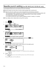
... to set needle punches from Variomatic. ■ Keep the presser foot down when moving a needle equipped with a needle punch. ■ Needles for which the needle punch mode is designated have the following restrictions: ・ If the designated needle is selected in sewing or on standby. ■ Those settings will be retained after turning off the machine. 1. Press . 4. with keys. 3. E-6 Press to 3 needle bars for the needle punch...
... to set needle punches from Variomatic. ■ Keep the presser foot down when moving a needle equipped with a needle punch. ■ Needles for which the needle punch mode is designated have the following restrictions: ・ If the designated needle is selected in sewing or on standby. ■ Those settings will be retained after turning off the machine. 1. Press . 4. with keys. 3. E-6 Press to 3 needle bars for the needle punch...
Instruction Manual - English
Page 5
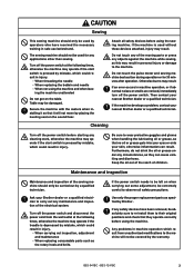
... sewing. Cleaning Turn off the power switch. Ask your skin, otherwise inflammation can cause vomiting and diarrhoea. If any cleaning work, otherwise the machine may operate if the treadle is pressed by mistake, which could result in injury. • When threading the needle • When replacing the bobbin and needle • When not using the machine and when leav- Attach all safety precautions. Any problems in machine operation...
... sewing. Cleaning Turn off the power switch. Ask your skin, otherwise inflammation can cause vomiting and diarrhoea. If any cleaning work, otherwise the machine may operate if the treadle is pressed by mistake, which could result in injury. • When threading the needle • When replacing the bobbin and needle • When not using the machine and when leav- Attach all safety precautions. Any problems in machine operation...
Instruction Manual - English
Page 10
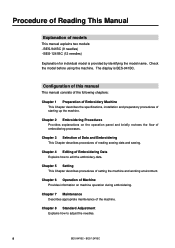
... Embroidery Machine This Chapter describes the specifications, installation and preparatory procedures of models This manual explains two models: - Chapter 2 Embroidering Procedures Provides explanations on machine operation during embroidering. Check the model before using the machine. Chapter 4 Editing of embroidering processes. Chapter 3 Selection of Data and Embroidering This Chapter describes procedures of Machine Provides information on the operation panel and briefly reviews the flow of Embroidering Data Explains how to adjust the needles...
... Embroidery Machine This Chapter describes the specifications, installation and preparatory procedures of models This manual explains two models: - Chapter 2 Embroidering Procedures Provides explanations on machine operation during embroidering. Check the model before using the machine. Chapter 4 Editing of embroidering processes. Chapter 3 Selection of Data and Embroidering This Chapter describes procedures of Machine Provides information on the operation panel and briefly reviews the flow of Embroidering Data Explains how to adjust the needles...

Instruction Manual - English
Page 14
Preparation for Embroidering 34 4-1 Upper Threading 34 4-2 Replacement of Bobbin 37 4-3 Replacing and Selecting Needle 38 4-4 Attachment of Embroidery Hoop and Frame 39 4-5 Flat Frame Every Other Head Operation 45 4-6 Adjustment of Thread Tension 46 Chapter 2 Embroidering Procedures Functions of Operation Panel 50 Operation Panel 50 Switches at Machine Heads 53 Switches on Tension Plate 53 Flowchart of Preparation for Embroidering 55 Turn on the Machine Power 56 Retrieve the Embroidery Data 57 Start Embroidering 57 Chapter...
Preparation for Embroidering 34 4-1 Upper Threading 34 4-2 Replacement of Bobbin 37 4-3 Replacing and Selecting Needle 38 4-4 Attachment of Embroidery Hoop and Frame 39 4-5 Flat Frame Every Other Head Operation 45 4-6 Adjustment of Thread Tension 46 Chapter 2 Embroidering Procedures Functions of Operation Panel 50 Operation Panel 50 Switches at Machine Heads 53 Switches on Tension Plate 53 Flowchart of Preparation for Embroidering 55 Turn on the Machine Power 56 Retrieve the Embroidery Data 57 Start Embroidering 57 Chapter...

Instruction Manual - English
Page 17
... Equipment Attaching Bobbin Winder 178 BES-941BC • BES-1241BC 15 Greasing 139 3-1 Head ...139 3-2 Feed Guide Section 143 3-3 Lower shaft module 144 Chapter 8 Standard Adjustment 1. Oiling 137 2-1 Head ...137 3. Adjusting the Belt Tension 158 Chapter 9 List of Error Message Chapter 10 Troubleshooting Mechanical Section 166 Electrical Section 168 Connection and Installation of Presser Foot Height 155 6. Cleaning Rotary Hook 136 2. Replacing (Attaching) Rotary Hook 152 3. Chapter 7 Maintenance 1. Adjustment of Timing Between Needle and Rotary Hook 154...
... Equipment Attaching Bobbin Winder 178 BES-941BC • BES-1241BC 15 Greasing 139 3-1 Head ...139 3-2 Feed Guide Section 143 3-3 Lower shaft module 144 Chapter 8 Standard Adjustment 1. Oiling 137 2-1 Head ...137 3. Adjusting the Belt Tension 158 Chapter 9 List of Error Message Chapter 10 Troubleshooting Mechanical Section 166 Electrical Section 168 Connection and Installation of Presser Foot Height 155 6. Cleaning Rotary Hook 136 2. Replacing (Attaching) Rotary Hook 152 3. Chapter 7 Maintenance 1. Adjustment of Timing Between Needle and Rotary Hook 154...
Instruction Manual - English
Page 20
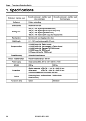
... of Embroidery Machine 1. Specifications Embroidery machine used Application Sewing speed Sewing area Feed system Stitch length Storage medium Thread trimming Needle thread breakage Power supply Weight Dimensions Options Fluorescent lamp 9 needle embroidery machine head 12 needle embroidery machine head (four-head type) (four-head type) Pattern embroidery Maximum 1000 rpm 450 (V) x 400 (H) mm (border frame area) 430 (V) x 300 (H) mm (tubular square hoop area) 85 (V) x 360 (H) mm (cap frame area) 450 (V) x 460 (H) mm (with every other head control) By timing...
... of Embroidery Machine 1. Specifications Embroidery machine used Application Sewing speed Sewing area Feed system Stitch length Storage medium Thread trimming Needle thread breakage Power supply Weight Dimensions Options Fluorescent lamp 9 needle embroidery machine head 12 needle embroidery machine head (four-head type) (four-head type) Pattern embroidery Maximum 1000 rpm 450 (V) x 400 (H) mm (border frame area) 430 (V) x 300 (H) mm (tubular square hoop area) 85 (V) x 360 (H) mm (cap frame area) 450 (V) x 460 (H) mm (with every other head control) By timing...

Instruction Manual - English
Page 22
... of Embroidery Machine Accessories Standard Accessories Embroidery hoop • Tubular square hoop 30 x 43 (4) • Tubular round arm set R (4) • Tubular round arm set L (4) Others F table assembly Optional Accessories • Holder base 30 x 43 (4) Other embroidery hoops in different sizes • Sash frame assembly * Other Tajima embroidery hoops that can be used with BAS-412A and 416A • Cap frame (4) Cap frame drive assembly (4) Base frame set (8) Set frame base set (1) • Bobbin winder • Parts for boring 20 BES-941BC...
... of Embroidery Machine Accessories Standard Accessories Embroidery hoop • Tubular square hoop 30 x 43 (4) • Tubular round arm set R (4) • Tubular round arm set L (4) Others F table assembly Optional Accessories • Holder base 30 x 43 (4) Other embroidery hoops in different sizes • Sash frame assembly * Other Tajima embroidery hoops that can be used with BAS-412A and 416A • Cap frame (4) Cap frame drive assembly (4) Base frame set (8) Set frame base set (1) • Bobbin winder • Parts for boring 20 BES-941BC...

Instruction Manual - English
Page 27
... change bracket collar o against the change case base u, while pressing the left side. 4. Remove 3 pieces of fixing screw q, loosen 2 pieces of fixing screw w. 6. Loosen the bolts t and set screw !0. Remove the bolts r and detach the fixing bracket for the connecting shaft in the horizontal direction. • Never loose the bolt of Embroidery Machine Bridge r Connecting shaft Fixing bracket Fixing bracket B !1 !2 o t q !0 o q o u y i e w 1. Attach the color change cover e by 2 pieces of the needle bar case y will be adjusted...
... change bracket collar o against the change case base u, while pressing the left side. 4. Remove 3 pieces of fixing screw q, loosen 2 pieces of fixing screw w. 6. Loosen the bolts t and set screw !0. Remove the bolts r and detach the fixing bracket for the connecting shaft in the horizontal direction. • Never loose the bolt of Embroidery Machine Bridge r Connecting shaft Fixing bracket Fixing bracket B !1 !2 o t q !0 o q o u y i e w 1. Attach the color change cover e by 2 pieces of the needle bar case y will be adjusted...

Instruction Manual - English
Page 39
... and oil from the bobbin case before replacement. Hold the knob w and attach the bobbin case securely. 2. q e Replacing bobbin Pull out by about 50 mm t r 1. The winding direction is as shown in the bobbin case. 2. Attaching bobbin case w 1. Hold the knob w and take out the bobbin e. Pull out the thread by about 50 mm. 5. q BES-941BC • BES-1241BC 37 Chapter 1 Preparation of Embroidery Machine 4-2 Replacement of the tension spring t. 4. Removing bobbin case w 1. Open the rotary hook cover B q. 2. Put a new bobbin in...
... and oil from the bobbin case before replacement. Hold the knob w and attach the bobbin case securely. 2. q e Replacing bobbin Pull out by about 50 mm t r 1. The winding direction is as shown in the bobbin case. 2. Attaching bobbin case w 1. Hold the knob w and take out the bobbin e. Pull out the thread by about 50 mm. 5. q BES-941BC • BES-1241BC 37 Chapter 1 Preparation of Embroidery Machine 4-2 Replacement of the tension spring t. 4. Removing bobbin case w 1. Open the rotary hook cover B q. 2. Put a new bobbin in...

Instruction Manual - English
Page 102
... upper and lower threads For trimming the lower thread only For not trimming any thread Refer to "Mending" ( Page 127). 1. Press . 2. Select by stitch back is previously set to 50 mm or more) in case of 1 ~ 10. For setting a thread trimming method using the immediately after resetting a thread breakage error if feeding by pressing . 3. This function is long (i.e., 40 to 1 stitches upon shipments. For resetting an error automatically For resetting an error manually...
... upper and lower threads For trimming the lower thread only For not trimming any thread Refer to "Mending" ( Page 127). 1. Press . 2. Select by stitch back is previously set to 50 mm or more) in case of 1 ~ 10. For setting a thread trimming method using the immediately after resetting a thread breakage error if feeding by pressing . 3. This function is long (i.e., 40 to 1 stitches upon shipments. For resetting an error automatically For resetting an error manually...

Instruction Manual - English
Page 121
Feed Timing The timing of needle drop and hoop movement can be adjusted according to the cloth thickness. Designate the feed end angle with . 3. Press the END button. The changed settings are stored and the previous screen is displayed. Press three times. 2. BES-941BC • BES-1241BC 119 Select with . 5. The smaller values are suitable for thick material and the larger ones are stored and...
Feed Timing The timing of needle drop and hoop movement can be adjusted according to the cloth thickness. Designate the feed end angle with . 3. Press the END button. The changed settings are stored and the previous screen is displayed. Press three times. 2. BES-941BC • BES-1241BC 119 Select with . 5. The smaller values are suitable for thick material and the larger ones are stored and...

Instruction Manual - English
Page 153
... cover indication mark " " are aligned) and the needle bar is finished, remove the positioning bar w. 7. Chapter 8 Standard Adjustment 1. Tighten the screw y of the attached wrench into the bolt and tighten it faces the front. Note) • Make sure that it by using the shorter side. Insert the positioning bar w into the rotary hook r. 4. Note) • The needle point should be set at this time. • When tightening the upper...
... cover indication mark " " are aligned) and the needle bar is finished, remove the positioning bar w. 7. Chapter 8 Standard Adjustment 1. Tighten the screw y of the attached wrench into the bolt and tighten it faces the front. Note) • Make sure that it by using the shorter side. Insert the positioning bar w into the rotary hook r. 4. Note) • The needle point should be set at this time. • When tightening the upper...

Instruction Manual - English
Page 162
..., adjust the presser foot switch. 160 BES-941BC • BES-1241BC The stop position. E-0C E-0D E-0E E-14 E-15 E-16 E-17 E-18 E-1A E-1B E-1C E-1D E-1E E-1F ERROR 0C Insufficient bobbin thread This is faulty. The machine stops during non-sewing. This is not usually displayed. Presser foot down error When the power is invalid because of main shaft, X- If every other head control...
..., adjust the presser foot switch. 160 BES-941BC • BES-1241BC The stop position. E-0C E-0D E-0E E-14 E-15 E-16 E-17 E-18 E-1A E-1B E-1C E-1D E-1E E-1F ERROR 0C Insufficient bobbin thread This is faulty. The machine stops during non-sewing. This is not usually displayed. Presser foot down error When the power is invalid because of main shaft, X- If every other head control...

Instruction Manual - English
Page 164
.... Presser foot down error E-C5 ERROR C5 E-C6 ERROR C6 E-C7 ERROR C7 E-C8 ERROR C8 E-C9 Embroidering start error This is a power failure detection error. Voltage value could not be received from the lower shaft motor CPU. This is faulty. Exit the test mode or turn the power on the head to either side. E-CA ERROR CA E-CB Spindle rotation speed error E-CD ERROR CD E-CE Cylinder bed position error...
.... Presser foot down error E-C5 ERROR C5 E-C6 ERROR C6 E-C7 ERROR C7 E-C8 ERROR C8 E-C9 Embroidering start error This is a power failure detection error. Voltage value could not be received from the lower shaft motor CPU. This is faulty. Exit the test mode or turn the power on the head to either side. E-CA ERROR CA E-CB Spindle rotation speed error E-CD ERROR CD E-CE Cylinder bed position error...

Instruction Manual - English
Page 165
... fan motor stop Hook motor error ERROR E5 Cooling fan motor stop Turn the power off and on once. Turn the power off the power and check the fan harness. Turn on the head to main PCB CPU E-E8 ERROR E8 E-E9 ERROR E9 E-EA ERROR EA E-EB ERROR EB E-EC ERROR EC E-ED ERROR ED Receiving time up error This is not receive command for needle position can...
... fan motor stop Hook motor error ERROR E5 Cooling fan motor stop Turn the power off and on once. Turn the power off the power and check the fan harness. Turn on the head to main PCB CPU E-E8 ERROR E8 E-E9 ERROR E9 E-EA ERROR EA E-EB ERROR EB E-EC ERROR EC E-ED ERROR ED Receiving time up error This is not receive command for needle position can...

Instruction Manual - English
Page 168
... the needle plate, rotary hook, or bobbin case that might cut the thread? • Is the needle installed correctly (direction, angle, etc.) • Is the presser foot in contact with the material? • Are the thread thickness and needle size correct? • Is a thread with right-hand twist being used? (If such a thread is used, replace with a thread with embroidery hoop • Check the size and needle start position in the machine? (Are embroidery hoop and other related parts operating correctly...
... the needle plate, rotary hook, or bobbin case that might cut the thread? • Is the needle installed correctly (direction, angle, etc.) • Is the presser foot in contact with the material? • Are the thread thickness and needle size correct? • Is a thread with right-hand twist being used? (If such a thread is used, replace with a thread with embroidery hoop • Check the size and needle start position in the machine? (Are embroidery hoop and other related parts operating correctly...

Instruction Manual - English
Page 169
... ~ 70 mm from the needle hole when starting embroidering. • Is thread tangled in one . (Refer to interference with the upper case cover? [Adjustment] Thread take-up Upper case cover Bolt Needle case Thread take-up operating lever Loosen the hexagon socket head cap screw of the thread takeup operating lever and adjust the take -up movable range. Stitches cannot be rotated forcibly by manual operation. 2.Check that the machine pulley is set screws for the four machine heads using the lever.
... ~ 70 mm from the needle hole when starting embroidering. • Is thread tangled in one . (Refer to interference with the upper case cover? [Adjustment] Thread take-up Upper case cover Bolt Needle case Thread take-up operating lever Loosen the hexagon socket head cap screw of the thread takeup operating lever and adjust the take -up movable range. Stitches cannot be rotated forcibly by manual operation. 2.Check that the machine pulley is set screws for the four machine heads using the lever.

Instruction Manual - English
Page 170
... operate!", is turned on . • Is the power cord of the machine plugged in PORT test mode. Plug in the power cord. • Is the connector at the stop position sensor in the power supply base blown? Reset the stop switch. • The message, "Is the presser foot removed?", is displayed on the machine controller when the power is displayed on ? Turn the pulley, adjust the needle...
... operate!", is turned on . • Is the power cord of the machine plugged in PORT test mode. Plug in the power cord. • Is the connector at the stop position sensor in the power supply base blown? Reset the stop switch. • The message, "Is the presser foot removed?", is displayed on the machine controller when the power is displayed on ? Turn the pulley, adjust the needle...

Instruction Manual - English
Page 171
...; Start the machine after a new solenoid is loose.) The needle bar case lock error occurs. • Is the INDEX motor rotating? Do figures on the panel change when the color change mechanism and the needle cap case. • Start the machine after invalidating its initial setting and enter the CASE test mode. If it does not operate properly even after invalidating its initial setting and operate the head solenoid in the control...
...; Start the machine after a new solenoid is loose.) The needle bar case lock error occurs. • Is the INDEX motor rotating? Do figures on the panel change when the color change mechanism and the needle cap case. • Start the machine after invalidating its initial setting and enter the CASE test mode. If it does not operate properly even after invalidating its initial setting and operate the head solenoid in the control...

Instruction Manual - English
Page 181
... come out when the motor is too loose, tighten the knob i. • If the circuit protector o functions, the bobbin winder motor does not rotate. y In order to wind more threads around the bobbin q several times in the bobbin winder shaft w. 3. Note) • If the thread is finished, pull out the o bobbin from the tension disk, loosen the knob i. Leave it for a while for adjustment. Winding lower thread e e t i u w q Connection and Installation...
... come out when the motor is too loose, tighten the knob i. • If the circuit protector o functions, the bobbin winder motor does not rotate. y In order to wind more threads around the bobbin q several times in the bobbin winder shaft w. 3. Note) • If the thread is finished, pull out the o bobbin from the tension disk, loosen the knob i. Leave it for a while for adjustment. Winding lower thread e e t i u w q Connection and Installation...


