
Assembly Manual
Page 1
BOWFLEX ® Power Pro ASSEMBLY MANUAL Includes Instructions for Bowflex Power Pro Attachments and Upgrades.
BOWFLEX ® Power Pro ASSEMBLY MANUAL Includes Instructions for Bowflex Power Pro Attachments and Upgrades.
Assembly Manual
Page 2
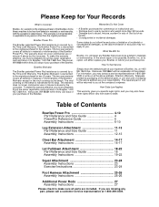
... as floods). • Consequential or incidental damages. Table of Contents Bowflex Power Pro 4-10 Part Reference and Size Guide 4 PowerPro Reference Guide 5 Assembly Instructions 6-10 Leg Extension Attachment 11-13 Part Reference and Size Guide 11 Assembly Instructions 12-13 Chest Bar Attachment 14-17 Assembly Instructions 15-17 Lat Pulldown Attachment 18-22 Part Reference...
... as floods). • Consequential or incidental damages. Table of Contents Bowflex Power Pro 4-10 Part Reference and Size Guide 4 PowerPro Reference Guide 5 Assembly Instructions 6-10 Leg Extension Attachment 11-13 Part Reference and Size Guide 11 Assembly Instructions 12-13 Chest Bar Attachment 14-17 Assembly Instructions 15-17 Lat Pulldown Attachment 18-22 Part Reference...
Assembly Manual
Page 3
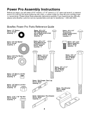
Please follow these assembly instructions carefully. Bowflex Power Pro Parts Reference Guide Name: 1/4" Washer Part #: 90156 Quantity: 1 Name: #12 x 3/4" Self Tapping Screw (the medium-sized screw) Part #: 90194 Quantity: 4 Name: 3/8" ..., a 7/16" wrench, a 1/2" open end wrench, a crescent wrench (to hold the bolt while tightening with other), a rubber mallet (for assistance. 1-800-269-3539. Power Pro Assembly Instructions Before you begin, you experience any difficulty, please call a Bowflex customer service representative and ask for step #5) and a phillips head (+) screw driver.
Please follow these assembly instructions carefully. Bowflex Power Pro Parts Reference Guide Name: 1/4" Washer Part #: 90156 Quantity: 1 Name: #12 x 3/4" Self Tapping Screw (the medium-sized screw) Part #: 90194 Quantity: 4 Name: 3/8" ..., a 7/16" wrench, a 1/2" open end wrench, a crescent wrench (to hold the bolt while tightening with other), a rubber mallet (for assistance. 1-800-269-3539. Power Pro Assembly Instructions Before you begin, you experience any difficulty, please call a Bowflex customer service representative and ask for step #5) and a phillips head (+) screw driver.
Assembly Manual
Page 5
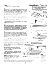
.... Now, locate the bolt keeper for the other bolt keeper. Slide them through the four holes in Pivot Bracket. IMPORTANT: Place Seat Rail so that assembly and slide it into the bolt keeper. Take that the end of the rail is flush with the end of the Pivot Bracket. Repeat for... Rear Leg Bolt Keeper. Pulley Frame Install the rail so the four bolts at the front of the Seat Rail channel from the opposite end. Assembling the Power Pro Components for the other bolt keeper. Rear Leg Bolt Keeper (marked with an R) Once you remove and reinstall the knob make sure it to...
.... Now, locate the bolt keeper for the other bolt keeper. Slide them through the four holes in Pivot Bracket. IMPORTANT: Place Seat Rail so that assembly and slide it into the bolt keeper. Take that the end of the rail is flush with the end of the Pivot Bracket. Repeat for... Rear Leg Bolt Keeper. Pulley Frame Install the rail so the four bolts at the front of the Seat Rail channel from the opposite end. Assembling the Power Pro Components for the other bolt keeper. Rear Leg Bolt Keeper (marked with an R) Once you remove and reinstall the knob make sure it to...

Assembly Manual
Page 6
... locks Seat into the openings of the Main Frame and secure with the channels along the sides of the Seat Rail. Secure them with full assembly. Note: If you purchased a CHEST BAR attachment, do not install the u-bar as shown in , you can install the two End Caps at right. 2b... Quick Release Hinge End Cap 2b. Step 2: Locate Seat and Bench and separate from one quarter turn allows Seat to slide freely. Components for this assembly are in Boxes 2 and 3 2a. Pull out the Seat Locking Pin in order to page 16, step 5, of the Seat Rail. Seat Rail Slide Seat...
... locks Seat into the openings of the Main Frame and secure with the channels along the sides of the Seat Rail. Secure them with full assembly. Note: If you purchased a CHEST BAR attachment, do not install the u-bar as shown in , you can install the two End Caps at right. 2b... Quick Release Hinge End Cap 2b. Step 2: Locate Seat and Bench and separate from one quarter turn allows Seat to slide freely. Components for this assembly are in Boxes 2 and 3 2a. Pull out the Seat Locking Pin in order to page 16, step 5, of the Seat Rail. Seat Rail Slide Seat...

Assembly Manual
Page 7
... 2 1/2" Tighten U-Bar securely. Note: If the screws do not go in screw threads. 5a. Step 4: Locate the Vertical Mainframe. Power Rod Pack Components for this assembly are in Box 1 Vertical Main Frame #12 Screw 8 Use the 3/8" x 4" Hex Head Bolt to tighten both top & bottom bolts ...same time evenly. Do not overtighten. 3/8" x 4" Hex Head Screw Components for this assembly are in Box 2 Vertical Main Frame Step 5: Locate the Power Rod Pack. Attach U-Bar portion of the Power Rod Pack. For easy installment, use soap or other lubricant in easily, use a ...
... 2 1/2" Tighten U-Bar securely. Note: If the screws do not go in screw threads. 5a. Step 4: Locate the Vertical Mainframe. Power Rod Pack Components for this assembly are in Box 1 Vertical Main Frame #12 Screw 8 Use the 3/8" x 4" Hex Head Bolt to tighten both top & bottom bolts ...same time evenly. Do not overtighten. 3/8" x 4" Hex Head Screw Components for this assembly are in Box 2 Vertical Main Frame Step 5: Locate the Power Rod Pack. Attach U-Bar portion of the Power Rod Pack. For easy installment, use soap or other lubricant in easily, use a ...

Assembly Manual
Page 8
... tighten a #14 screw into the fourth hole of the side channel of the bracket as shown below. There is no pre-drilled hole for this assembly are in place and securely tightened 1/4" Washer #14 Screw Pull Pin out and turn clockwise, one quarter turn to make sure all three screws are...
... tighten a #14 screw into the fourth hole of the side channel of the bracket as shown below. There is no pre-drilled hole for this assembly are in place and securely tightened 1/4" Washer #14 Screw Pull Pin out and turn clockwise, one quarter turn to make sure all three screws are...

Assembly Manual
Page 9
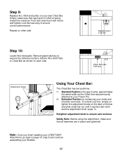
Locate Nonskid Pads. Place Nonskid Pads here (facing top) Components for this assembly are in Box 2 Hook Hand-Grips into place by inserting D-Ring into Snap Hook on end of cables. D-Ring Cable 10 Step 8: Place Bench onto the Bowflex. Note: If you installed a CHEST BAR Attachment, please go to Pulley Frame as shown. Adhere Nonskid Pads to page 16, step 8. Unwrap Cables and Pulleys. Remove paper backing to expose the adhesive surface.
Locate Nonskid Pads. Place Nonskid Pads here (facing top) Components for this assembly are in Box 2 Hook Hand-Grips into place by inserting D-Ring into Snap Hook on end of cables. D-Ring Cable 10 Step 8: Place Bench onto the Bowflex. Note: If you installed a CHEST BAR Attachment, please go to Pulley Frame as shown. Adhere Nonskid Pads to page 16, step 8. Unwrap Cables and Pulleys. Remove paper backing to expose the adhesive surface.
Assembly Manual
Page 10
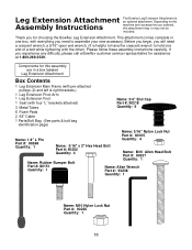
...1 11 Before you begin, you will need to assemble your new accessory. If you for choosing the Bowflex Leg Extension Attachment. Please follow these assembly instructions carefully. Thank you experience any difficulty, please call a Bowflex customer service representative for this attachment may or may ... at 1-800-269-3539. Depending on the Assembly Instructions machine and accessories you ordered, this assembly are in one end of a bolt while tightening with the other). Leg Extension Attachment The Bowflex Leg Extension Attachment is helpful to have the crescent...
...1 11 Before you begin, you will need to assemble your new accessory. If you for choosing the Bowflex Leg Extension Attachment. Please follow these assembly instructions carefully. Thank you experience any difficulty, please call a Bowflex customer service representative for this attachment may or may ... at 1-800-269-3539. Depending on the Assembly Instructions machine and accessories you ordered, this assembly are in one end of a bolt while tightening with the other). Leg Extension Attachment The Bowflex Leg Extension Attachment is helpful to have the crescent...

Assembly Manual
Page 11
... Main Frame as indicated. Insert and tighten with one 5/16" Lock Nut. Tighten pre-placed 1/4" x 3/4" Machine Screw. Installing the Leg Extension Attachment Components for this assembly are in a box labeled Leg Extension Attachment Step 1: Rotate Pivot Arm Bracket as indicated. Step 2: Secure Pivot Arm Bracket by inserting one 5/16" x 2" Hex Head...
... Main Frame as indicated. Insert and tighten with one 5/16" Lock Nut. Tighten pre-placed 1/4" x 3/4" Machine Screw. Installing the Leg Extension Attachment Components for this assembly are in a box labeled Leg Extension Attachment Step 1: Rotate Pivot Arm Bracket as indicated. Step 2: Secure Pivot Arm Bracket by inserting one 5/16" x 2" Hex Head...

Assembly Manual
Page 12
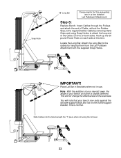
... inserting the "L" Pin through the two holes on Pivot Arm Bracket. Do not overtighten. Tighten so that Pivot Arm Assembly does not have excessive side to Bowflex Cables. Slide Foam Pads onto metal tube and insert End Caps. Use Snap Hook to fasten Leg Extension Cables to side... Arm Components for this assembly are facing as indicated below. Important! Secure by sliding Bench forward, then placing Leg Extension Bracket onto end of Seat Rail. Secure with an allen wrench). Make sure Pulleys are in use, unhook Leg Extension Cables from Bowflex Cables. 13 Thread cable...
... inserting the "L" Pin through the two holes on Pivot Arm Bracket. Do not overtighten. Tighten so that Pivot Arm Assembly does not have excessive side to Bowflex Cables. Slide Foam Pads onto metal tube and insert End Caps. Use Snap Hook to fasten Leg Extension Cables to side... Arm Components for this assembly are facing as indicated below. Important! Secure by sliding Bench forward, then placing Leg Extension Bracket onto end of Seat Rail. Secure with an allen wrench). Make sure Pulleys are in use, unhook Leg Extension Cables from Bowflex Cables. 13 Thread cable...

Assembly Manual
Page 13
...Exercise Instruction Sheet Assembly Instructions Please check to assemble your new accessory. Please follow these assembly instructions carefully. If you experience any part, please call a Bowflex customer service representative and ask for choosing the Bowflex Chest Bar Attachment. Chest Bar Attachment Assembly Instructions The ...Components for this attachment may or may not be included. Depending on the machine and accessories you ordered, this assembly are missing any difficulty, please call a customer service representative at 1-800-269-3539. Before you begin, you for...
...Exercise Instruction Sheet Assembly Instructions Please check to assemble your new accessory. Please follow these assembly instructions carefully. If you experience any part, please call a Bowflex customer service representative and ask for choosing the Bowflex Chest Bar Attachment. Chest Bar Attachment Assembly Instructions The ...Components for this attachment may or may not be included. Depending on the machine and accessories you ordered, this assembly are missing any difficulty, please call a customer service representative at 1-800-269-3539. Before you begin, you for...

Assembly Manual
Page 14
Chest Bar Assembly Instructions Step 1: Slide Seat to end of seat rail and lower to machine base. Vertical Main Frame Remove the Vertical Main Frame with Rod Pack ... need to be used in a box labeled Chest Bar Attachment Step 2: Remove indicated bolts going through pulley frame and Vertical Main Frame. Components for this assembly are in a later step.
Chest Bar Assembly Instructions Step 1: Slide Seat to end of seat rail and lower to machine base. Vertical Main Frame Remove the Vertical Main Frame with Rod Pack ... need to be used in a box labeled Chest Bar Attachment Step 2: Remove indicated bolts going through pulley frame and Vertical Main Frame. Components for this assembly are in a later step.

Assembly Manual
Page 15
... the machine frame where you removed. Secure with Rod Pack that you removed in Step Two, attach Chest Bar to machine frame. Components for this assembly are connected to page 8, step 4 and continue assembling your Bowflex. Using the nuts and bolts that you previously removed in step two.
... the machine frame where you removed. Secure with Rod Pack that you removed in Step Two, attach Chest Bar to machine frame. Components for this assembly are connected to page 8, step 4 and continue assembling your Bowflex. Using the nuts and bolts that you previously removed in step two.
Assembly Manual
Page 16
... Lock Nut securely to expose the adhesive surface. Note: Once you finish installing your CHEST BAR Attachment, go back to page 10, step 8 and continue assembling your chest and shoulder exercises. Remove paper backing to ensure correct performance. To extend your new Chest Bar. Adhere Non-skid Pads to Chest Bar... until it came, approximately the same width as shown on your bar, simply untighten the adjustment knobs on other side. Retighten adjustment knob to your Power Pro. 2) Extended Position for enhancing your Bowflex. 17
... Lock Nut securely to expose the adhesive surface. Note: Once you finish installing your CHEST BAR Attachment, go back to page 10, step 8 and continue assembling your chest and shoulder exercises. Remove paper backing to ensure correct performance. To extend your new Chest Bar. Adhere Non-skid Pads to Chest Bar... until it came, approximately the same width as shown on your bar, simply untighten the adjustment knobs on other side. Retighten adjustment knob to your Power Pro. 2) Extended Position for enhancing your Bowflex. 17

Assembly Manual
Page 17
Depending on the machine and accessories you ordered, this assembly are in a box labeled Lat Pulldown Attachment Box Contents 1 Cross Bar 1 Main Frame Lower Half 1 Upper Main Frame 2 Main Frame Brackets 1 T-Piece with pulley, and ...: Snap Hook Part #: 50334 Quantity: 2 Name: Plastic Bumper Part #: 98202 Quantity: 1 18 Components for this attachment may or may not be included. Lat Pulldown Attachment Assembly Instructions The Lat Pulldown Attachment is an optional attachment.
Depending on the machine and accessories you ordered, this assembly are in a box labeled Lat Pulldown Attachment Box Contents 1 Cross Bar 1 Main Frame Lower Half 1 Upper Main Frame 2 Main Frame Brackets 1 T-Piece with pulley, and ...: Snap Hook Part #: 50334 Quantity: 2 Name: Plastic Bumper Part #: 98202 Quantity: 1 18 Components for this attachment may or may not be included. Lat Pulldown Attachment Assembly Instructions The Lat Pulldown Attachment is an optional attachment.

Assembly Manual
Page 18
... bottom of the Main Frame Lower Half rests in between the Vertical Extrusion and the Seat Rail. Installing The Lat Pulldown Attachment Components for this assembly are facing downward and they rest on the bottom of the pulley frame.
... bottom of the Main Frame Lower Half rests in between the Vertical Extrusion and the Seat Rail. Installing The Lat Pulldown Attachment Components for this assembly are facing downward and they rest on the bottom of the pulley frame.

Assembly Manual
Page 19
...Screws Long Square Head Bolt 1/4" x 7" Flanges Step 5: Secure the Main Frame Brackets to your Bowflex by sliding the long Square Head Bolt through the holes on the Main Frame just below the Power Rod pack. Place the other bracket on the end of bolts and tighten Adjustment Screws. 20 ...Tighten Wing Nuts onto end of the brackets. Components for this assembly are seated in a box labeled Lat Pulldown Attachment Step 4:...
...Screws Long Square Head Bolt 1/4" x 7" Flanges Step 5: Secure the Main Frame Brackets to your Bowflex by sliding the long Square Head Bolt through the holes on the Main Frame just below the Power Rod pack. Place the other bracket on the end of bolts and tighten Adjustment Screws. 20 ...Tighten Wing Nuts onto end of the brackets. Components for this assembly are seated in a box labeled Lat Pulldown Attachment Step 4:...

Assembly Manual
Page 20
... Pulleys. Place Bumper over Lower and Upper Main Frame connection. Insert the 1/4" x 3 1/2" Hex Head Bolts through the main frame and the "T" Piece. Components for this assembly are in place. 21 Insert two 3/8" x 3 1/2" Hex Head Bolts into the top end of the Upper Main Frame as pictured.
... Pulleys. Place Bumper over Lower and Upper Main Frame connection. Insert the 1/4" x 3 1/2" Hex Head Bolts through the main frame and the "T" Piece. Components for this assembly are in place. 21 Insert two 3/8" x 3 1/2" Hex Head Bolts into the top end of the Upper Main Frame as pictured.
Assembly Manual
Page 21
Hook up the 30 pound Power Rods on both sides. This will note that your bench at this assembly are in use. Slide Cables into the tube beneath the "T" piece when not using Snap Hooks to attach the loop end of your bench now ...rests against the lat tower support block and not on the incline support bracket. Attach the Long Bar to the regular Bowflex Cable by...
Hook up the 30 pound Power Rods on both sides. This will note that your bench at this assembly are in use. Slide Cables into the tube beneath the "T" piece when not using Snap Hooks to attach the loop end of your bench now ...rests against the lat tower support block and not on the incline support bracket. Attach the Long Bar to the regular Bowflex Cable by...

