Installation guide
Page 2
..., use care not to the presence of uninsulated dangerous voltage within an equilateral triangle, as a CLASS 1 LASER PRODUCT according to follow this installation guide. AVIS RISQUE DE CHOC ÉLECTRIQUE NE PAS OUVRIR ATTENTION : POUR RÉDUIRE LE RISQUE DE DÉCHARGE ÉLECTRIQUE, ...apparatus shall not be exposed to dripping or splashing, and objects filled with arrowhead symbol, within the media center is located on your LIFESTYLE® media center and Acoustimass® module enclosures: The lightning flash with liquids, such as lighted candles, should not be placed on...
..., use care not to the presence of uninsulated dangerous voltage within an equilateral triangle, as a CLASS 1 LASER PRODUCT according to follow this installation guide. AVIS RISQUE DE CHOC ÉLECTRIQUE NE PAS OUVRIR ATTENTION : POUR RÉDUIRE LE RISQUE DE DÉCHARGE ÉLECTRIQUE, ...apparatus shall not be exposed to dripping or splashing, and objects filled with arrowhead symbol, within the media center is located on your LIFESTYLE® media center and Acoustimass® module enclosures: The lightning flash with liquids, such as lighted candles, should not be placed on...

Installation guide
Page 4
...service 34 Technical information 34 4 Safety Information 2 Introduction 5 Before you begin 5 Special indicator used in this book 5 Unpacking 5 System Installation 6 Cables and accessories 7 Placing your speakers 8 Left and right front speaker placement 8 Center speaker placement 9 Surround speaker placement 10 Acoustimass&#...18 Turning off the speakers in your TV 18 Connecting the system to power 19 Installing the remote control batteries 20 Finishing the basic installation 21 Installing the TV on/off sensor 23 Reference 24 Using alternate video connections 24 Connecting your...
...service 34 Technical information 34 4 Safety Information 2 Introduction 5 Before you begin 5 Special indicator used in this book 5 Unpacking 5 System Installation 6 Cables and accessories 7 Placing your speakers 8 Left and right front speaker placement 8 Center speaker placement 9 Surround speaker placement 10 Acoustimass&#...18 Turning off the speakers in your TV 18 Connecting the system to power 19 Installing the remote control batteries 20 Finishing the basic installation 21 Installing the TV on/off sensor 23 Reference 24 Using alternate video connections 24 Connecting your...
Installation guide
Page 6
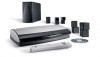
...Installation Figure 1 Components of the LIFESTYLE® DVD systems Media center Media center power supply ® Your system will have five of one type of cube speaker: Rubber foot for Jewel Cube® speaker or or Single cube speaker (LIFESTYLE® 18 Series II system) Cube speaker array (LIFESTYLE® 28 Series II & LIFESTYLE...Info Last 0 uMusic Rating Similar Whole CD CD # Playlist Rubber feet for cube speakers LIFESTYLE® 18, 28 LIFESTYLE® 38, 48 systems systems Acoustimass® module Rubber feet for Acoustimass module Media center power supply AC ...
...Installation Figure 1 Components of the LIFESTYLE® DVD systems Media center Media center power supply ® Your system will have five of one type of cube speaker: Rubber foot for Jewel Cube® speaker or or Single cube speaker (LIFESTYLE® 18 Series II system) Cube speaker array (LIFESTYLE® 28 Series II & LIFESTYLE...Info Last 0 uMusic Rating Similar Whole CD CD # Playlist Rubber feet for cube speakers LIFESTYLE® 18, 28 LIFESTYLE® 38, 48 systems systems Acoustimass® module Rubber feet for Acoustimass module Media center power supply AC ...
Installation guide
Page 7
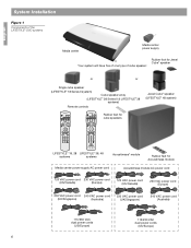
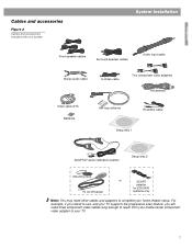
English Cables and accessories Figure 2 Cables and accessories included with your system System Installation L R Front speaker cables Surround speaker cables Audio input cable Stereo audio cable S-Video cable Two component video adapters FM antenna Video cable (6 ft) Batteries AM ...
English Cables and accessories Figure 2 Cables and accessories included with your system System Installation L R Front speaker cables Surround speaker cables Audio input cable Stereo audio cable S-Video cable Two component video adapters FM antenna Video cable (6 ft) Batteries AM ...
Installation guide
Page 8
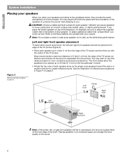
... system. Placing speakers in another direction to 20 feet (6.1 m) from the Acoustimass® module. • Rotate the top cube of the sound. 8 Bose recommends a maximum distance of 3 feet (1 m) from the picture. See the illustration of the TV screen so that speaker. You may wish to move,..., the left , or right front speakers will be in Figure 4 on smooth surfaces like marble, glass, or highly polished wood. English System Installation Placing your speakers When you . CAUTION: Choose a stable and level surface for example, be sure to place them at the edge of the ...
... system. Placing speakers in another direction to 20 feet (6.1 m) from the Acoustimass® module. • Rotate the top cube of the sound. 8 Bose recommends a maximum distance of 3 feet (1 m) from the picture. See the illustration of the TV screen so that speaker. You may wish to move,..., the left , or right front speakers will be in Figure 4 on smooth surfaces like marble, glass, or highly polished wood. English System Installation Placing your speakers When you . CAUTION: Choose a stable and level surface for example, be sure to place them at the edge of the ...
Installation guide
Page 9
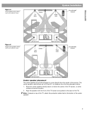
... location. 2. The center speaker cable allows up to the back of the picture. Figure 4 Cube speaker array placement and reflection rays Left front Center System Installation Right front Acoustimass® module English Figure 5 Single cube speaker placement and reflection rays Left surround Left front Center Right surround Right front Acoustimass module...
... location. 2. The center speaker cable allows up to the back of the picture. Figure 4 Cube speaker array placement and reflection rays Left front Center System Installation Right front Acoustimass® module English Figure 5 Single cube speaker placement and reflection rays Left surround Left front Center Right surround Right front Acoustimass module...
Installation guide
Page 10
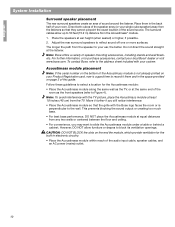
... ventilation for the Acoustimass module: • Place the Acoustimass module along the same wall as the front speakers (refer to Figure 4). English System Installation Surround speaker placement The rear surround speakers create an area of speaker mounting accessories, including stands and wall brackets. Note... to slide the Acoustimass module under a table or behind a cabinet. The longer the path from the listeners so that the grille with the Bose logo faces the room or is a good time to record it further if you may want to block its ventilation openings. Direct both cubes ...
... ventilation for the Acoustimass module: • Place the Acoustimass module along the same wall as the front speakers (refer to Figure 4). English System Installation Surround speaker placement The rear surround speakers create an area of speaker mounting accessories, including stands and wall brackets. Note... to slide the Acoustimass module under a table or behind a cabinet. The longer the path from the listeners so that the grille with the Bose logo faces the room or is a good time to record it further if you may want to block its ventilation openings. Direct both cubes ...
Installation guide
Page 11
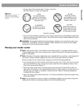
... you should not store tapes directly on your Product Registration card, now is not a short-term risk to your dealer or call Bose® customer service. English System Installation Figure 6 Right and wrong placements for the Acoustimass module • Put any side of this guide. DO NOT stand the module ... openings DO NOT stand the module on the floor. DO NOT stand it to the Bose address list included with the connectors facing the floor. Note: For convenience, until your system, is completely installed, you may wish to place the media center where you want to lift up the ...
... you should not store tapes directly on your Product Registration card, now is not a short-term risk to your dealer or call Bose® customer service. English System Installation Figure 6 Right and wrong placements for the Acoustimass module • Put any side of this guide. DO NOT stand the module ... openings DO NOT stand the module on the floor. DO NOT stand it to the Bose address list included with the connectors facing the floor. Note: For convenience, until your system, is completely installed, you may wish to place the media center where you want to lift up the ...
Installation guide
Page 12
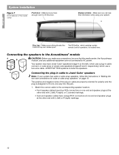
English System Installation Figure 7 Front features of the plug-in cable are not connected to AC power. Display window - Make sure you can see this door. LIFESTYLE® DVD systems include five speakers. Make sure you make any connections, be sure that the media center, the Acoustimass module, and any additional equipment ...
English System Installation Figure 7 Front features of the plug-in cable are not connected to AC power. Display window - Make sure you can see this door. LIFESTYLE® DVD systems include five speakers. Make sure you make any connections, be sure that the media center, the Acoustimass module, and any additional equipment ...
Installation guide
Page 13
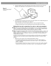
... the two-wire connections for cube or cube array speakers Note: The surround speaker cables are joined together for connecting the surround speakers. to the Bose address list included with L (left surround and right surround jacks. Insert the speaker plug of each cable fully into a notch at one end, with your... system. Note: To lengthen the speaker cables, use cable for your dealer or electronics store, or call Bose® customer service. Refer to -). To run the cables in cable connection System Installation 2.
... the two-wire connections for cube or cube array speakers Note: The surround speaker cables are joined together for connecting the surround speakers. to the Bose address list included with L (left surround and right surround jacks. Insert the speaker plug of each cable fully into a notch at one end, with your... system. Note: To lengthen the speaker cables, use cable for your dealer or electronics store, or call Bose® customer service. Refer to -). To run the cables in cable connection System Installation 2.
Installation guide
Page 14
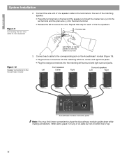
... FRONT L FRONT C FRONT R SURROUND L SURROUND R AUDIO INPUT OUTPUTS TO CUBE SPEAKERS FRONT SURROUND L C L R R POWER 100-120/200-240VAC 50/60 Hz 350W MAX. English System Installation Figure 9 Connecting the two-wire cable to secure the wire.
... FRONT L FRONT C FRONT R SURROUND L SURROUND R AUDIO INPUT OUTPUTS TO CUBE SPEAKERS FRONT SURROUND L C L R R POWER 100-120/200-240VAC 50/60 Hz 350W MAX. English System Installation Figure 9 Connecting the two-wire cable to secure the wire.
Installation guide
Page 15
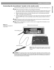
...) power outlet until all connections are completed. 2. Do not plug the other rooms" on the connector. 15 Note: Be sure that each jack. 1. English System Installation Connecting the Acoustimass® module to the media center Connect the Acoustimass module to other end into each connector is built into the media center...
...) power outlet until all connections are completed. 2. Do not plug the other rooms" on the connector. 15 Note: Be sure that each jack. 1. English System Installation Connecting the Acoustimass® module to the media center Connect the Acoustimass module to other end into each connector is built into the media center...

Installation guide
Page 16
...the AM antenna lead into the FM antenna jack. Note: AM radio reception may be used with the antenna. If necessary, contact a qualified installer. 16 Connecting the FM antenna Plug the connector on a wall, follow the instructions enclosed with your cable TV provider for optimum AM reception.... Experiment with the AM antenna. 3. Note: Make sure that the cable radio installation includes a signal splitter so that only the FM radio band, not the cable TV band, is made to the rear panel of the ...
...the AM antenna lead into the FM antenna jack. Note: AM radio reception may be used with the antenna. If necessary, contact a qualified installer. 16 Connecting the FM antenna Plug the connector on a wall, follow the instructions enclosed with your cable TV provider for optimum AM reception.... Experiment with the AM antenna. 3. Note: Make sure that the cable radio installation includes a signal splitter so that only the FM radio band, not the cable TV band, is made to the rear panel of the ...
Installation guide
Page 17
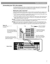
...connectors on each end. Note: It is used. Later in this guide This audio connection allows your TV to send sound to your LIFESTYLE® system This video connection allows you have fewer Video IN connections Component video connections are explained later in this case, use your TV...TV, you to use the ones for connecting additional components to your system quickly. This may connect a digital audio cable as well. English System Installation Connecting your TV to the Audio IN TV L and R on each end, or an optical cable, which Video IN jack is important to provide...
...connectors on each end. Note: It is used. Later in this guide This audio connection allows your TV to send sound to your LIFESTYLE® system This video connection allows you have fewer Video IN connections Component video connections are explained later in this case, use your TV...TV, you to use the ones for connecting additional components to your system quickly. This may connect a digital audio cable as well. English System Installation Connecting your TV to the Audio IN TV L and R on each end, or an optical cable, which Video IN jack is important to provide...
Installation guide
Page 18
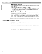
... you used on your TV, you used. To turn their sound off the speakers in your TV When you listen to TV sound through your LIFESTYLE® system, the speakers in your Operating Guide for more than once, depending on how to set to their lowest volume. Refer to your TV... owner's guide for information on which numbered connection you will need to select the input which connects the media center to the TV. English System Installation Making a video connection On your Media Center, connect the Composite Video Out to a Video In connection on your TV. See Figure 13. • Use a single...
... you used on your TV, you used. To turn their sound off the speakers in your TV When you listen to TV sound through your LIFESTYLE® system, the speakers in your Operating Guide for more than once, depending on how to set to their lowest volume. Refer to your TV... owner's guide for information on which numbered connection you will need to select the input which connects the media center to the TV. English System Installation Making a video connection On your Media Center, connect the Composite Video Out to a Video In connection on your TV. See Figure 13. • Use a single...
Installation guide
Page 19
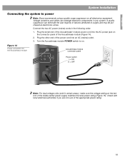
... voltage units (sold in the following order: 1. Check with local electrical authorities if you are not sure of the appropriate power rating. 19 English System Installation Connecting the system to power Note: Bose recommends using a quality surge suppressor on the connector panel of the Acoustimass module (Figure 14). 2.
... voltage units (sold in the following order: 1. Check with local electrical authorities if you are not sure of the appropriate power rating. 19 English System Installation Connecting the system to power Note: Bose recommends using a quality surge suppressor on the connector panel of the Acoustimass module (Figure 14). 2.
Installation guide
Page 20
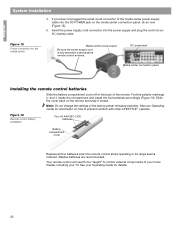
...connection panel, do so now (Figure 15). 5. Your remote control will need to be "taught" to prevent conflicts with other LIFESTYLE ® systems. Figure 16 Remote control battery installation Four (4) AAA (IEC-LR3) batteries + ++ + Battery compartment cover Replace all four batteries when the remote control stops operating... center power supply Be sure the power supply cord is fully extended; DC power jack Media center connection panel Installing the remote control batteries Slide the battery compartment cover off of the back of the factory-preset miniature switches. English System...
...connection panel, do so now (Figure 15). 5. Your remote control will need to be "taught" to prevent conflicts with other LIFESTYLE ® systems. Figure 16 Remote control battery installation Four (4) AAA (IEC-LR3) batteries + ++ + Battery compartment cover Replace all four batteries when the remote control stops operating... center power supply Be sure the power supply cord is fully extended; DC power jack Media center connection panel Installing the remote control batteries Slide the battery compartment cover off of the back of the factory-preset miniature switches. English System...
Installation guide
Page 21
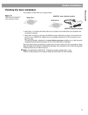
... is in place and you through the ADAPTiQ audio calibration process, which tailors the sound of your LIFESTYLE® system and your speaker placement to the acoustics of your listening area. Note: The 220-240V LIFESTYLE ® 18 Series II system includes Disc 1 only. You may want to do not need to... instructions for Disc 2 below. 21 The special headset, designed to complete the process. Put it when the acoustic measurements will not disturb anyone. English System Installation Finishing the basic installation Your system comes with two compact discs.
... is in place and you through the ADAPTiQ audio calibration process, which tailors the sound of your LIFESTYLE® system and your speaker placement to the acoustics of your listening area. Note: The 220-240V LIFESTYLE ® 18 Series II system includes Disc 1 only. You may want to do not need to... instructions for Disc 2 below. 21 The special headset, designed to complete the process. Put it when the acoustic measurements will not disturb anyone. English System Installation Finishing the basic installation Your system comes with two compact discs.

Installation guide
Page 22
...you are to the placement of your system and your television. 2. Keep the headset and discs together in their instructions, the installation of your LIFESTYLE® DVD system is complete and its performance is tailored to follow the instructions. Put on page 21 at any time. ...English System Installation Figure 18 Using the AdaptiQ calibration headset Using the ADAPTiQ® audio calibration system 1. Disc 2 will be instructed when ...
...you are to the placement of your system and your television. 2. Keep the headset and discs together in their instructions, the installation of your LIFESTYLE® DVD system is complete and its performance is tailored to follow the instructions. Put on page 21 at any time. ...English System Installation Figure 18 Using the AdaptiQ calibration headset Using the ADAPTiQ® audio calibration system 1. Disc 2 will be instructed when ...
Installation guide
Page 23
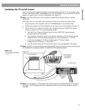
... the best location for mounting the sensor. In the menu navigate to control your TV" in Figure 19. 3. D. Figure 19 TV on/off sensor installed on your TV Rear of your TV as shown in your Operating Guide. Note: The TV on/off sensor is selected. Temporarily position the TV... cord connector into the TV SENSOR jack on . Note: DO NOT use SCART connectors. C. See "Programming your LIFESTYLE® system remote to TV Power (directly above TV Power Status). English System Installation Installing the TV on/off sensor The TV on/off sensor enables the system to automatically switch the TV on...
... the best location for mounting the sensor. In the menu navigate to control your TV" in Figure 19. 3. D. Figure 19 TV on/off sensor installed on your TV Rear of your TV as shown in your Operating Guide. Note: The TV on/off sensor is selected. Temporarily position the TV... cord connector into the TV SENSOR jack on . Note: DO NOT use SCART connectors. C. See "Programming your LIFESTYLE® system remote to TV Power (directly above TV Power Status). English System Installation Installing the TV on/off sensor The TV on/off sensor enables the system to automatically switch the TV on...


