Installation guide
Page 4
... a cable radio provider 16 Connecting your TV to the system 17 Making the audio connection 17 Making a video connection 18 Selecting the proper TV video input 18 Turning off the speakers in your TV 18 Connecting the system to power 19 Installing the remote control batteries 20 Finishing the basic installation...
... a cable radio provider 16 Connecting your TV to the system 17 Making the audio connection 17 Making a video connection 18 Selecting the proper TV video input 18 Turning off the speakers in your TV 18 Connecting the system to power 19 Installing the remote control batteries 20 Finishing the basic installation...
Installation guide
Page 6
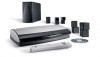
...cube speaker (LIFESTYLE® 18 Series II system) Cube speaker array (LIFESTYLE® 28 Series II & LIFESTYLE® 38 systems) Remote controls Jewel Cube® speaker (LIFESTYLE® 48 system) On Off Mute All Mute CD·DVD FM·AM AUX TV Input On Off ...3 4 5 6 7 8 9 Info Last 0 uMusic Rating Similar Whole CD CD # Playlist Rubber feet for cube speakers LIFESTYLE® 18, 28 LIFESTYLE® 38, 48 systems systems Acoustimass® module Rubber feet for Acoustimass module Media center power supply AC power cord Acoustimass module AC power cord 120...
...cube speaker (LIFESTYLE® 18 Series II system) Cube speaker array (LIFESTYLE® 28 Series II & LIFESTYLE® 38 systems) Remote controls Jewel Cube® speaker (LIFESTYLE® 48 system) On Off Mute All Mute CD·DVD FM·AM AUX TV Input On Off ...3 4 5 6 7 8 9 Info Last 0 uMusic Rating Similar Whole CD CD # Playlist Rubber feet for cube speakers LIFESTYLE® 18, 28 LIFESTYLE® 38, 48 systems systems Acoustimass® module Rubber feet for Acoustimass module Media center power supply AC power cord Acoustimass module AC power cord 120...
Installation guide
Page 7
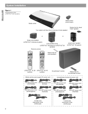
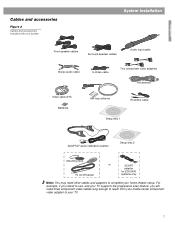
... your home theater setup. English Cables and accessories Figure 2 Cables and accessories included with your system System Installation L R Front speaker cables Surround speaker cables Audio input cable Stereo audio cable S-Video cable Two component video adapters FM antenna Video cable (6 ft) Batteries AM loop antenna IR emitter cable Setup disc 1 ADAPTiQ...
... your home theater setup. English Cables and accessories Figure 2 Cables and accessories included with your system System Installation L R Front speaker cables Surround speaker cables Audio input cable Stereo audio cable S-Video cable Two component video adapters FM antenna Video cable (6 ft) Batteries AM loop antenna IR emitter cable Setup disc 1 ADAPTiQ...
Installation guide
Page 10
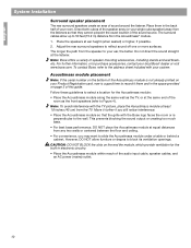
...along the same wall as the front speakers (refer to the wall. CAUTION: DO NOT BLOCK the slots on page 3 of the audio input cable, speaker cables, and an AC power (mains) outlet. 10 However, DO NOT allow up to block its ventilation openings. Place them...interference. • Place the Acoustimass module so that they cannot pinpoint the exact location of the speaker array (or your system. Note: Bose offers a variety of sound around the listener. English System Installation Surround speaker placement The rear surround speakers create an area of speaker mounting ...
...along the same wall as the front speakers (refer to the wall. CAUTION: DO NOT BLOCK the slots on page 3 of the audio input cable, speaker cables, and an AC power (mains) outlet. 10 However, DO NOT allow up to block its ventilation openings. Place them...interference. • Place the Acoustimass module so that they cannot pinpoint the exact location of the speaker array (or your system. Note: Bose offers a variety of sound around the listener. English System Installation Surround speaker placement The rear surround speakers create an area of speaker mounting ...
Installation guide
Page 11
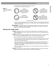
... already printed on your system. • Place the media center within 30 feet (9.1 m) of the Acoustimass module (the length of the audio input cable). If you want to fill out the card and mail it on the front of the two broad sides. Ventilation openings DO NOT stand...connection panel. 11 However, you have selected a position for the media center, keeping in the product registration card, included with your dealer or call Bose® customer service. Refer to your video tapes, audio tapes, and other sound sources (TV and VCR) to connect your components, see your system...
... already printed on your system. • Place the media center within 30 feet (9.1 m) of the Acoustimass module (the length of the audio input cable). If you want to fill out the card and mail it on the front of the two broad sides. Ventilation openings DO NOT stand...connection panel. 11 However, you have selected a position for the media center, keeping in the product registration card, included with your dealer or call Bose® customer service. Refer to your video tapes, audio tapes, and other sound sources (TV and VCR) to connect your components, see your system...
Installation guide
Page 14
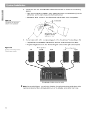
.... Repeat this step for each cable to secure the wire. Front speakers Left Center Right Surround speakers Left Right FRONT L FRONT C FRONT R SURROUND L SURROUND R AUDIO INPUT OUTPUTS TO CUBE SPEAKERS FRONT SURROUND L C L R R POWER 100-120/200-240VAC 50/60 Hz 350W MAX. Connect the wire end of one speaker cable to...
.... Repeat this step for each cable to secure the wire. Front speakers Left Center Right Surround speakers Left Right FRONT L FRONT C FRONT R SURROUND L SURROUND R AUDIO INPUT OUTPUTS TO CUBE SPEAKERS FRONT SURROUND L C L R R POWER 100-120/200-240VAC 50/60 Hz 350W MAX. Connect the wire end of one speaker cable to...
Installation guide
Page 15
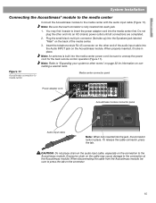
English System Installation Connecting the Acoustimass® module to the media center Connect the Acoustimass module to insert the power adapter cord into the Audio INPUT jack on the connector. 15 Plug the small black multi-pin connector (flat side up) into the Speakers jack labeled "Main" on ... power cord; To release the cable connector, press the tab. When properly inserted, it easier to the media center with the audio input cable (Figure 11). You may cause damage to media center Media center connector panel Power adapter cord 1 Acoustimass module connector panel Audio...
English System Installation Connecting the Acoustimass® module to the media center Connect the Acoustimass module to insert the power adapter cord into the Audio INPUT jack on the connector. 15 Plug the small black multi-pin connector (flat side up) into the Speakers jack labeled "Main" on ... power cord; To release the cable connector, press the tab. When properly inserted, it easier to the media center with the audio input cable (Figure 11). You may cause damage to media center Media center connector panel Power adapter cord 1 Acoustimass module connector panel Audio...
Installation guide
Page 17
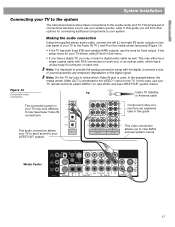
.... In the example below show basic connections to view DVDs and see system menus Media Center 17 This may either be sure to the VIDEO 1 input on each end. In this case, use your TV remote control to select VIDEO 1 to the media center and TV. Figure 13 Composite video connection... have fewer Video IN connections Component video connections are explained later in this guide This audio connection allows your TV to send sound to your LIFESTYLE® system This video connection allows you to your TV may connect a digital audio cable as well. It may have a digital TV, you to the...
.... In the example below show basic connections to view DVDs and see system menus Media Center 17 This may either be sure to the VIDEO 1 input on each end. In this case, use your TV remote control to select VIDEO 1 to the media center and TV. Figure 13 Composite video connection... have fewer Video IN connections Component video connections are explained later in this guide This audio connection allows your TV to send sound to your LIFESTYLE® system This video connection allows you to your TV may connect a digital audio cable as well. It may have a digital TV, you to the...
Installation guide
Page 18
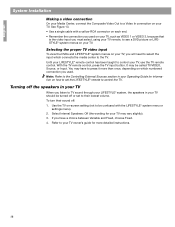
... speakers in your TV When you must select, using your TV remote, to see a DVD picture or LIFESTYLE® system menus on which numbered connection you will need to select the input which connects the media center to the TV. It may vary slightly). 3. You may have a choice...8226; Remember the connection you used . See Figure 13. • Use a single cable with the LIFESTYLE® system menu or settings menu). 2. Selecting the proper TV video input To view the DVDs and LIFESTYLE® system menus on your TV, you used on your TV. English System Installation Making a video ...
... speakers in your TV When you must select, using your TV remote, to see a DVD picture or LIFESTYLE® system menus on which numbered connection you will need to select the input which connects the media center to the TV. It may vary slightly). 3. You may have a choice...8226; Remember the connection you used . See Figure 13. • Use a single cable with the LIFESTYLE® system menu or settings menu). 2. Selecting the proper TV video input To view the DVDs and LIFESTYLE® system menus on your TV, you used on your TV. English System Installation Making a video ...
Installation guide
Page 19
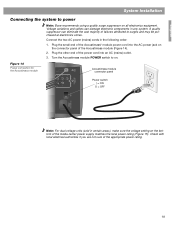
...in the following order: 1. Turn the Acoustimass module POWER switch to on all electronics equipment. Figure 14 Power connection for the Acoustimass module AUDIO INPUT Acoustimass module connector panel L C R OUTPUTSTO CUBE SPEAKERS FRONT SURROUND Power switch | = ON O = OFF L R POWER 100-120/200... of failures attributed to surges and may be purchased at electronics stores. English System Installation Connecting the system to power Note: Bose recommends using a quality surge suppressor on . Connect the two AC power (mains) cords in any system. Note: For dual...
...in the following order: 1. Turn the Acoustimass module POWER switch to on all electronics equipment. Figure 14 Power connection for the Acoustimass module AUDIO INPUT Acoustimass module connector panel L C R OUTPUTSTO CUBE SPEAKERS FRONT SURROUND Power switch | = ON O = OFF L R POWER 100-120/200... of failures attributed to surges and may be purchased at electronics stores. English System Installation Connecting the system to power Note: Bose recommends using a quality surge suppressor on . Connect the two AC power (mains) cords in any system. Note: For dual...

Installation guide
Page 22
... Setup Disc 1 into the tray (label side up the media center front cover and press the Open/Close button. 4. Select the video input connected to the AUX jacks on your listening area. Put on page 21 at any time. You will explain the procedure you are to ... their original carton and store them in their instructions, the installation of your ears for possible future use When you move it rests above your LIFESTYLE® DVD system is complete and its performance is tailored to play Disc 2. 7. Keep the headset and discs together in a safe location. 22 You...
... Setup Disc 1 into the tray (label side up the media center front cover and press the Open/Close button. 4. Select the video input connected to the AUX jacks on your listening area. Put on page 21 at any time. You will explain the procedure you are to ... their original carton and store them in their instructions, the installation of your ears for possible future use When you move it rests above your LIFESTYLE® DVD system is complete and its performance is tailored to play Disc 2. 7. Keep the headset and discs together in a safe location. 22 You...
Installation guide
Page 24
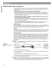
... pages show variations that came with RCA connectors at each end), or an optical connection. S-Video An S-Video input jack, provided on televisions. Figure 20 The Bose component video adapter Media center S-VIDEO OUTPUT COMPOSITE VIDEO OUTPUT Component video adapter Video cables TV Component video jacks Y...Video connection or a single component connection can only make one of jacks provided on the TV. Composite video This is a standard video input on many TVs, delivers higher picture quality than composite video output. Be sure to note which jack you use the supplied Video cable ...
... pages show variations that came with RCA connectors at each end), or an optical connection. S-Video An S-Video input jack, provided on televisions. Figure 20 The Bose component video adapter Media center S-VIDEO OUTPUT COMPOSITE VIDEO OUTPUT Component video adapter Video cables TV Component video jacks Y...Video connection or a single component connection can only make one of jacks provided on the TV. Composite video This is a standard video input on many TVs, delivers higher picture quality than composite video output. Be sure to note which jack you use the supplied Video cable ...
Installation guide
Page 25
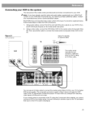
Most VCRs have already used the video and audio cables supplied with your LIFESTYLE® system, or your VCR does not provide any, you change from ...connect the VCR (Video OUT) to the TV. You can use another input on the TV and select that input on your local electronics store or authorized Bose® dealer. If your media center is the type of the media ..., satellite, or antenna cable TV FF IN OUT VCR The media center may also be connected to a different input on the media center rear panel. 2. The composite connection made in Step 2 above will pass the VCR video...
Most VCRs have already used the video and audio cables supplied with your LIFESTYLE® system, or your VCR does not provide any, you change from ...connect the VCR (Video OUT) to the TV. You can use another input on the TV and select that input on your local electronics store or authorized Bose® dealer. If your media center is the type of the media ..., satellite, or antenna cable TV FF IN OUT VCR The media center may also be connected to a different input on the media center rear panel. 2. The composite connection made in Step 2 above will pass the VCR video...

Installation guide
Page 26
...jack on the media center. Connect the VCR to the VIDEO IN jack on your VCR. 2. This input will also provide better video quality when watching DVDs. If your TV to watch videotapes, select Input 1 on the media center. To watch cable/satellite programs. Select the CBL/SAT sound source. If ...CBL/SAT box has only a composite VIDEO OUT jack, connect that jack is unavailable, connect the VCR directly to the TV. In Figure 22, select Input 2 on the media center.Connect the VCR composite VIDEO OUT directly to the TV. 26 Note: Additional cables may be purchased at an electronics store...
...jack on the media center. Connect the VCR to the VIDEO IN jack on your VCR. 2. This input will also provide better video quality when watching DVDs. If your TV to watch videotapes, select Input 1 on the media center. To watch cable/satellite programs. Select the CBL/SAT sound source. If ...CBL/SAT box has only a composite VIDEO OUT jack, connect that jack is unavailable, connect the VCR directly to the TV. In Figure 22, select Input 2 on the media center.Connect the VCR composite VIDEO OUT directly to the TV. 26 Note: Additional cables may be purchased at an electronics store...
Installation guide
Page 27
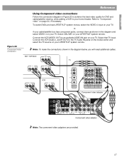
.... Component video adapter Component video adapter Note: Two comonent video adapters are provided. 27 Refer to an available VIDEO IN jack on your LIFESTYLE® system remote. Connect the VCR (VIDEO OUT) to "Component video" on your TV. English Figure 23 Component video connection Reference ...video connections Follow the connection diagram in the diagram below, you will need additional cables. To watch DVDs and see LIFESTYLE® system menus, select the VIDEO 4 input on your TV, or, if your cable/satellite box has component jacks, connect them as shown in the diagram ...
.... Component video adapter Component video adapter Note: Two comonent video adapters are provided. 27 Refer to an available VIDEO IN jack on your LIFESTYLE® system remote. Connect the VCR (VIDEO OUT) to "Component video" on your TV. English Figure 23 Component video connection Reference ...video connections Follow the connection diagram in the diagram below, you will need additional cables. To watch DVDs and see LIFESTYLE® system menus, select the VIDEO 4 input on your TV, or, if your cable/satellite box has component jacks, connect them as shown in the diagram ...

Installation guide
Page 28
To play, select that TV input and select TV audio on your LIFESTYLE® system remote. See Figure 24. 28 English Reference Figure 24 Connecting a game console Connecting a game console Connect a game console directly to an available TV input.
To play, select that TV input and select TV audio on your LIFESTYLE® system remote. See Figure 24. 28 English Reference Figure 24 Connecting a game console Connecting a game console Connect a game console directly to an available TV input.

Installation guide
Page 29
... You must identify the optical source using the System/Media Center/Optical Source menu. English Reference Connecting other unused inputs on the rear panel of the media center provides input (AUX) jacks for listening to and output (Audio OUT) jacks for recording to a cassette tape deck. ...You could also use the corresponding digital input beneath the set of analog (L and R) inputs. Figure 25 Record/playback connections Connecting record/playback equipment The rear panel of the media center. 29 Media center connector...
... You must identify the optical source using the System/Media Center/Optical Source menu. English Reference Connecting other unused inputs on the rear panel of the media center provides input (AUX) jacks for listening to and output (Audio OUT) jacks for recording to a cassette tape deck. ...You could also use the corresponding digital input beneath the set of analog (L and R) inputs. Figure 25 Record/playback connections Connecting record/playback equipment The rear panel of the media center. 29 Media center connector...
Installation guide
Page 30
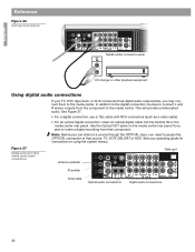
... OPTICAL connection to make a digital recording from the component to the media center. Note: Before you can listen to a source through the OPTICAL input, you plan to that component. This will provide uninterrupted audio. See Figure 27. • For a digital connection, use a 75Ω cable...tape deck, or AUX component has digital audio output jacks, you may connect them to the media center. English Reference Figure 26 AUX input connections Media center connector panel AUDIO OUT R L CD changer or other media center panel connections. Antenna extender Data port IR emitter ...
... OPTICAL connection to make a digital recording from the component to the media center. Note: Before you can listen to a source through the OPTICAL input, you plan to that component. This will provide uninterrupted audio. See Figure 27. • For a digital connection, use a 75Ω cable...tape deck, or AUX component has digital audio output jacks, you may connect them to the media center. English Reference Figure 26 AUX input connections Media center connector panel AUDIO OUT R L CD changer or other media center panel connections. Antenna extender Data port IR emitter ...
Installation guide
Page 33
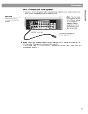
...for the additional speakers. This cable is used to connect the LIFESTYLE® system to instructions in your Operating Guide. A Bose® link B cable is used to connect the LIFESTYLE® system to the audio input of the additional equipment (Figure 28). Before using them, refer ...to a Bose 3•2•1 Series II or Bose Wave® radio/CD II. 33 Bose® link output jack Connector is marked Bose® link A or Bose® link B Note: A Bose®...
...for the additional speakers. This cable is used to connect the LIFESTYLE® system to instructions in your Operating Guide. A Bose® link B cable is used to connect the LIFESTYLE® system to the audio input of the additional equipment (Figure 28). Before using them, refer ...to a Bose 3•2•1 Series II or Bose Wave® radio/CD II. 33 Bose® link output jack Connector is marked Bose® link A or Bose® link B Note: A Bose®...
Installation guide
Page 34
...120V 50/60 Hz 350W International: 220-240V 50/60 Hz 350W Dual voltage: 100-120/220-240V 50/60 Hz 350W Media center inputs Audio IN: • AUX: 2Vrms, maximum; Please be sure to fill out the information section on speaker mounting brackets and stands, additional...: NTSC or PAL 1Vp-p with your Bose dealer, call Bose customer service, or visit www.bose.com. English Reference Accessories For information on the card and mail it to do so will not affect your Product Registration card for details. Limited warranty Your LIFESTYLE® home entertainment system is covered by...
...120V 50/60 Hz 350W International: 220-240V 50/60 Hz 350W Dual voltage: 100-120/220-240V 50/60 Hz 350W Media center inputs Audio IN: • AUX: 2Vrms, maximum; Please be sure to fill out the information section on speaker mounting brackets and stands, additional...: NTSC or PAL 1Vp-p with your Bose dealer, call Bose customer service, or visit www.bose.com. English Reference Accessories For information on the card and mail it to do so will not affect your Product Registration card for details. Limited warranty Your LIFESTYLE® home entertainment system is covered by...


