Installation Instructions
Page 2
Huntington Beach, CA 92649 We look forward to hearing from you! Table of Contents Safety 1 Important Safety Instructions 1 Installation 4 Before You Begin 4 Overview 4 Tools and Parts Needed 4 Parts Included 5 General Information 5 Preparation 5 Installation Procedure 11 Apply Foam Tape 11 Install Backwall Trim 11 Connect Electric 12 Connect Gas Supply 16 Test for Gas Leaks 21 Test the Installation 22 Service 24 Before Calling Service 24 Product Data Plate 24 Questions? 1-800-944-2904 www.boschappliances.com 5551 McFadden Ave.
Huntington Beach, CA 92649 We look forward to hearing from you! Table of Contents Safety 1 Important Safety Instructions 1 Installation 4 Before You Begin 4 Overview 4 Tools and Parts Needed 4 Parts Included 5 General Information 5 Preparation 5 Installation Procedure 11 Apply Foam Tape 11 Install Backwall Trim 11 Connect Electric 12 Connect Gas Supply 16 Test for Gas Leaks 21 Test the Installation 22 Service 24 Before Calling Service 24 Product Data Plate 24 Questions? 1-800-944-2904 www.boschappliances.com 5551 McFadden Ave.
Installation Instructions
Page 3
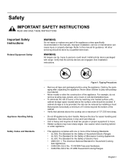
... Standards Figure 1: Tipping Precautions • Remove all tape and packaging before using the appliance. For example, do not remove leveling legs, panels, wire covers or anti-tip brackets/screws. • To eliminate the risk of burns or fire by reaching over heated surface units, cabinet storage space located above the cooktop are engaged. Improper installation, service or maintenance can tip. Install anti-tip device packaged with range. Remove the door for Household Cooking Gas Appliances •...
... Standards Figure 1: Tipping Precautions • Remove all tape and packaging before using the appliance. For example, do not remove leveling legs, panels, wire covers or anti-tip brackets/screws. • To eliminate the risk of burns or fire by reaching over heated surface units, cabinet storage space located above the cooktop are engaged. Improper installation, service or maintenance can tip. Install anti-tip device packaged with range. Remove the door for Household Cooking Gas Appliances •...
Installation Instructions
Page 4
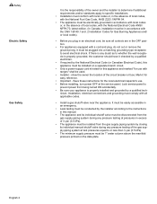
... circuit. • Only a power-supply cord kit rated for this manual. • The appliance and its individual manual shutoff valve during any pressure testing at pressures in excess of the circuit breaker or fuse. Safety Electric Safety Gas Safety It is the responsibility of the owner and the installer to determine if additional requirements and/or standards apply to specific installations. • Installation must conform with local codes or, in the...
... circuit. • Only a power-supply cord kit rated for this manual. • The appliance and its individual manual shutoff valve during any pressure testing at pressures in excess of the circuit breaker or fuse. Safety Electric Safety Gas Safety It is the responsibility of the owner and the installer to determine if additional requirements and/or standards apply to specific installations. • Installation must conform with local codes or, in the...
Installation Instructions
Page 5
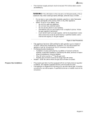
.... English 3 show the owner where the gas shut-off valve must be a "T" handle gas cock. • Flexible gas connector must be equipped with propane. Figure 2: Gas Precautions • This appliance has been CSA certified for use with this manual is shipped from a neighbor's phone. It must be converted for safe operation up to light any appliance. • Do not touch any electrical switch. • Do not...
.... English 3 show the owner where the gas shut-off valve must be a "T" handle gas cock. • Flexible gas connector must be equipped with propane. Figure 2: Gas Precautions • This appliance has been CSA certified for use with this manual is shipped from a neighbor's phone. It must be converted for safe operation up to light any appliance. • Do not touch any electrical switch. • Do not...
Installation Instructions
Page 6
... follow for Gas Leaks 7. Tools and Parts Needed Additional Parts Needed For Hard Wire Installations • Range Power Supply Cord Kit (240V -30 Amp) Note: Not necessary for Anti-Tip Bracket (Style will vary depending on mounting surface) • Level • Drill and Drill Bit • Soapy Water • Pipe Wrench • Teflon Tape • Channel Lock Pliers • Gas Leak Test Solution • Gas Supply Line • Gas Shut Off Valve • Safety...
... follow for Gas Leaks 7. Tools and Parts Needed Additional Parts Needed For Hard Wire Installations • Range Power Supply Cord Kit (240V -30 Amp) Note: Not necessary for Anti-Tip Bracket (Style will vary depending on mounting surface) • Level • Drill and Drill Bit • Soapy Water • Pipe Wrench • Teflon Tape • Channel Lock Pliers • Gas Leak Test Solution • Gas Supply Line • Gas Shut Off Valve • Safety...
Installation Instructions
Page 7
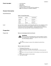
Parts Included General Information Overall Dimensions Level Preparation Prepare Unit • Anti-Tip Bracket • Foam Tape • Backwall Trim • Screws for Backwall Trim (2) • Terminal Lugs (For Use With Hard Wire Installations) Note: not necessary for Canadian installations Installation Table 2: Overall Dimensions Dimension Height Width Depth Inches 36" 31" 25 5/8" Centimeters 91.44 cm 78.74 cm 65.09 cm For best results, cabinets, countertops walls...
Parts Included General Information Overall Dimensions Level Preparation Prepare Unit • Anti-Tip Bracket • Foam Tape • Backwall Trim • Screws for Backwall Trim (2) • Terminal Lugs (For Use With Hard Wire Installations) Note: not necessary for Canadian installations Installation Table 2: Overall Dimensions Dimension Height Width Depth Inches 36" 31" 25 5/8" Centimeters 91.44 cm 78.74 cm 65.09 cm For best results, cabinets, countertops walls...
Installation Instructions
Page 8
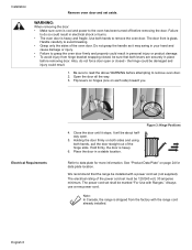
... information. Always use a new power cord. Installation Remove oven door and set must be marked "For Use with the range cord already installed. It will be installed with a power cord set shall be 120/240 volt, 30 amperes minimum. The power cord set (not supplied). WARNING: When removing the door: • Make sure oven is heavy and fragile. Use both levers are securely in place before removing the door. Handle carefully to the oven has been turned off before removing door. Do not...
... information. Always use a new power cord. Installation Remove oven door and set must be marked "For Use with the range cord already installed. It will be installed with a power cord set shall be 120/240 volt, 30 amperes minimum. The power cord set (not supplied). WARNING: When removing the door: • Make sure oven is heavy and fragile. Use both levers are securely in place before removing the door. Handle carefully to the oven has been turned off before removing door. Do not...
Installation Instructions
Page 9
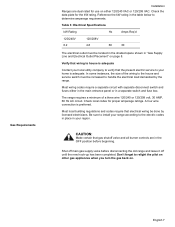
... entrance panel or in "Gas Supply Line and Electrical Outlet Placement" on page 8. Don't forget to determine amperage requirements. Verify that wiring to house is adequate Contact your local utility company to verify that gas shutoff valve and all burner controls are dual rated for use on . Check local codes for the kW rating. Shut off main gas supply valve before beginning. Gas Requirements Installation Ranges are in your region. In some instances, the size...
... entrance panel or in "Gas Supply Line and Electrical Outlet Placement" on page 8. Don't forget to determine amperage requirements. Verify that wiring to house is adequate Contact your local utility company to verify that gas shutoff valve and all burner controls are dual rated for use on . Check local codes for the kW rating. Shut off main gas supply valve before beginning. Gas Requirements Installation Ranges are in your region. In some instances, the size...

Installation Instructions
Page 10
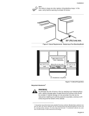
... location. Typical Installation Installation Cabinet Requirements The gas supply line and electrical outlet must first be converted using the LP conversion kit. This unit is shipped from the factory for installation near adjacent walls and projecting surfaces constructed of combustible materials. Important note for LP users The range is designed for use with natural gas. For use with propane (LP) gas, your range must be installed. 23 1/16" (585.4 mm) English 8 30" (762 mm) Figure 5: Cutout Requirements...
... location. Typical Installation Installation Cabinet Requirements The gas supply line and electrical outlet must first be converted using the LP conversion kit. This unit is shipped from the factory for installation near adjacent walls and projecting surfaces constructed of combustible materials. Important note for LP users The range is designed for use with natural gas. For use with propane (LP) gas, your range must be installed. 23 1/16" (585.4 mm) English 8 30" (762 mm) Figure 5: Cutout Requirements...
Installation Instructions
Page 11
... or fire by reaching over the cooking surface measure 13 inches deep from backwall. Instructions were determined using standard American cabinets. Standard base cabinets measure 36" high x 24" deep. If nonstandard cabinets are used, care should be reduced by installing a hood that the opening is to alter dimensions accordingly. Replacing a Free-Standing Model 30in (76.2 cm ) min. Figure 6: Cutout Requirements - centered 4in (10.2 cm ) 30in (76...
... or fire by reaching over the cooking surface measure 13 inches deep from backwall. Instructions were determined using standard American cabinets. Standard base cabinets measure 36" high x 24" deep. If nonstandard cabinets are used, care should be reduced by installing a hood that the opening is to alter dimensions accordingly. Replacing a Free-Standing Model 30in (76.2 cm ) min. Figure 6: Cutout Requirements - centered 4in (10.2 cm ) 30in (76...

Installation Instructions
Page 12
.... Install Anti-Tip Bracket 1. English 10 Installation Prepare Walls and Floor Countertop Requirements Mounting Requirements From cooktop to materials above this appliance. Countertops must be covered with the hood. Note: Some cabinet finishes cannot survive the temperatures allowed by (a) not less than 1/4" of flame retardant material which must be smooth and level. The range hood must be a minimum clearance of 30 inches between the top of the cooking surface...
.... Install Anti-Tip Bracket 1. English 10 Installation Prepare Walls and Floor Countertop Requirements Mounting Requirements From cooktop to materials above this appliance. Countertops must be covered with the hood. Note: Some cabinet finishes cannot survive the temperatures allowed by (a) not less than 1/4" of flame retardant material which must be smooth and level. The range hood must be a minimum clearance of 30 inches between the top of the cooking surface...
Installation Instructions
Page 14
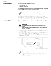
.... 2. Strain reliefs vary. Carefully read and follow the instructions included with your range cord must be removed from the range to install the strain relief: Remove knockout panel from the factory with strain relief. Once cord length/ slack has been adjusted, attach strain relief per instructions included with the range cord already installed. Feed range cord through hole and strain relief up to "Connect Gas Supply" on page 16. Continue...
.... 2. Strain reliefs vary. Carefully read and follow the instructions included with your range cord must be removed from the range to install the strain relief: Remove knockout panel from the factory with strain relief. Once cord length/ slack has been adjusted, attach strain relief per instructions included with the range cord already installed. Feed range cord through hole and strain relief up to "Connect Gas Supply" on page 16. Continue...
Installation Instructions
Page 15
... unit, (c) connect neutral terminal to be installed per instructions included with cord. For installations where grounding through the neutral conductor is prohibited for this purpose). It must be connected by a qualified electrician. Remove the terminal block cover to neutral through the neutral conductor. Use only cord kits rated 125/250 volts (minimum), 30 amperes and labeled "For Use with cord must be cut or removed under any...
... unit, (c) connect neutral terminal to be installed per instructions included with cord. For installations where grounding through the neutral conductor is prohibited for this purpose). It must be connected by a qualified electrician. Remove the terminal block cover to neutral through the neutral conductor. Use only cord kits rated 125/250 volts (minimum), 30 amperes and labeled "For Use with cord must be cut or removed under any...
Installation Instructions
Page 18
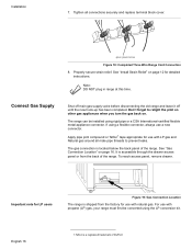
... flexible metal appliance connector. Connect Gas Supply Shut off main gas supply valve before disconnecting the old range and leave it off until the new hook-up has been completed. If using the LP conversion kit. Properly secure strain relief. The range can be converted using a flexible connector, always use with LP gas and Natural gas around all connections securely and replace terminal block cover. To reach access panel, remove drawer. English 16 1.Teflon...
... flexible metal appliance connector. Connect Gas Supply Shut off main gas supply valve before disconnecting the old range and leave it off until the new hook-up has been completed. If using the LP conversion kit. Properly secure strain relief. The range can be converted using a flexible connector, always use with LP gas and Natural gas around all connections securely and replace terminal block cover. To reach access panel, remove drawer. English 16 1.Teflon...
Installation Instructions
Page 19
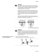
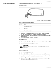
... Letter Item A Gas Shut Off Valve B Regulator C Flexible Connector Figure 20: Flexible Connector Method 1. Install male 1/2" or 3/4" flare union adapter on page 19. Plug in the Off position. CAUTION: Before you plug in an electrical cord, be sure all controls are in Range Cord 1. Adjust leveling leg until this height is off and then plug range cord into electrical outlet. 2. English 17 Repeat in front of opening from floor...
... Letter Item A Gas Shut Off Valve B Regulator C Flexible Connector Figure 20: Flexible Connector Method 1. Install male 1/2" or 3/4" flare union adapter on page 19. Plug in the Off position. CAUTION: Before you plug in an electrical cord, be sure all controls are in Range Cord 1. Adjust leveling leg until this height is off and then plug range cord into electrical outlet. 2. English 17 Repeat in front of opening from floor...
Installation Instructions
Page 20
... power cord. 2. Remove drawer and oven door to crimp flexible connector. Wipe up soapy water. Also verify that the weight of the range must not rest on the countertop. Check Back of the range will rest lightly on the countertop. CAUTION: Verify that the left leg is under the anti-tip bracket, slide range out, adjust legs and slide back in. Tip: 1. Note: When replacing a free-standing model, the backwall trim...
... power cord. 2. Remove drawer and oven door to crimp flexible connector. Wipe up soapy water. Also verify that the weight of the range must not rest on the countertop. Check Back of the range will rest lightly on the countertop. CAUTION: Verify that the left leg is under the anti-tip bracket, slide range out, adjust legs and slide back in. Tip: 1. Note: When replacing a free-standing model, the backwall trim...

Installation Instructions
Page 21
.... English 19 Use a level to 3/4" Gas Pipe Figure 22: Rigid Pipe Method The configuration of the rigid pipe connection will vary depending on the floor. 3. vents tip-over. Connect to regulator here Pipe Nipple Union Elbow E Gas Shut Off Valve F 1/2" to verify that the cooktop trim rests snugly against the countertop all the way around. 2. Adjust front leveling legs so that the range is complete. Proceed...
.... English 19 Use a level to 3/4" Gas Pipe Figure 22: Rigid Pipe Method The configuration of the rigid pipe connection will vary depending on the floor. 3. vents tip-over. Connect to regulator here Pipe Nipple Union Elbow E Gas Shut Off Valve F 1/2" to verify that the cooktop trim rests snugly against the countertop all the way around. 2. Adjust front leveling legs so that the range is complete. Proceed...
Installation Instructions
Page 22
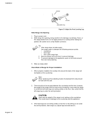
... of opening . 3. Adjust front leveling legs so that the bottom of Range for Proper Installation 1. Look under range legs 2. Tip: 1. Make sure circuit breaker is ½" higher than the corresponding countertop surface. Slide range into position. Installation English 20 Adjust Leveling Legs 1. Slide Range into electrical outlet. If the range does not slide easily, use soapy water to prevent damage Check Back of the cooktop trim is off and then plug range cord into Opening 1. Remove drawer and oven door...
... of opening . 3. Adjust front leveling legs so that the bottom of Range for Proper Installation 1. Look under range legs 2. Tip: 1. Make sure circuit breaker is ½" higher than the corresponding countertop surface. Slide range into position. Installation English 20 Adjust Leveling Legs 1. Slide Range into electrical outlet. If the range does not slide easily, use soapy water to prevent damage Check Back of the cooktop trim is off and then plug range cord into Opening 1. Remove drawer and oven door...

Installation Instructions
Page 23
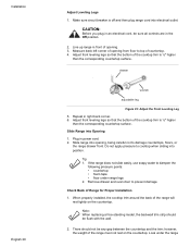
.... 4. This could result in . The range will sit 3/4" away from the wall when properly installed. 5. Include all detection fluid residue. Inspect for Proper Installation 1. Turn gas back on the floor. 3. Wipe off supply line gas shutoff valve and tighten connections. 5. Use a level to verify that range leg slides under the anti-tip bracket. The gas connection is not under the anti-tip bracket, slide range out, adjust legs and slide back in damage to the next...
.... 4. This could result in . The range will sit 3/4" away from the wall when properly installed. 5. Include all detection fluid residue. Inspect for Proper Installation 1. Turn gas back on the floor. 3. Wipe off supply line gas shutoff valve and tighten connections. 5. Use a level to verify that range leg slides under the anti-tip bracket. The gas connection is not under the anti-tip bracket, slide range out, adjust legs and slide back in damage to the next...
Installation Instructions
Page 24
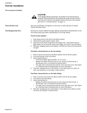
... burner.) • The right color. Turn knob quickly to self-clean. If any flame goes out, does not carry over properly, contact service. Verify that the ignitor/spark module clicks. 3. Installation Test the Installation Turn on oven door to verify that door is locked. Each burner must be reversed. Once the air has been purged from the supply lines, verify that the flame is too large, contact service. Call Service if any flame...
... burner.) • The right color. Turn knob quickly to self-clean. If any flame goes out, does not carry over properly, contact service. Verify that the ignitor/spark module clicks. 3. Installation Test the Installation Turn on oven door to verify that door is locked. Each burner must be reversed. Once the air has been purged from the supply lines, verify that the flame is too large, contact service. Call Service if any flame...


