
U8068 user's manual
Page 2
...Introduction 2 1-1. BIOS & Software 7 1-3. Layout of Contents Notice 1 Mainboard Features 2 1. CPU Fan Header: JCFAN1 12 3-3. Front Panel Connector: JPANEL1 14 4-2. Hard Disk Connectors: IDE1/IDE2 16 4-4. Wake On LAN Header: JWOL1 17 4-6. System Fan Header: JSFAN1 12 4. Clear CMOS Jumper: JCMOS1 17 4-7. Mainboard Configuration 8 2-1. Component Index 9 3. CPU Socket 478 Configuration Steps 10 3-2. Front USB Header: JUSB3 18 4-8. Front USB Header: JUSB4 18 4-9. 5V / 5VSB Selection for KB: JKBV1 18 i Table of U8068 8 2-2. ATX 20-pin Power Connector: JATXPWR1...
...Introduction 2 1-1. BIOS & Software 7 1-3. Layout of Contents Notice 1 Mainboard Features 2 1. CPU Fan Header: JCFAN1 12 3-3. Front Panel Connector: JPANEL1 14 4-2. Hard Disk Connectors: IDE1/IDE2 16 4-4. Wake On LAN Header: JWOL1 17 4-6. System Fan Header: JSFAN1 12 4. Clear CMOS Jumper: JCMOS1 17 4-7. Mainboard Configuration 8 2-1. Component Index 9 3. CPU Socket 478 Configuration Steps 10 3-2. Front USB Header: JUSB3 18 4-8. Front USB Header: JUSB4 18 4-9. 5V / 5VSB Selection for KB: JKBV1 18 i Table of U8068 8 2-2. ATX 20-pin Power Connector: JATXPWR1...

U8068 user's manual
Page 6
...-bit PCI bus slots Fast EtherNet 10/ 100 1-Port PHY/ Transceiver: 1.Dual Speed - 100/ 10 Mbps. 2.Half and Full Duplex. 3.MII Interface to 15 minutes. Chapter 1 Motherboard Description Shadow RAM: Motherboard is equipped with Monitor Power 1-3 High Resolution CRT RGB Interface 1.250 MHz RAMDAC on chip with Gamma Correction. 2.Horizontal / Vertical Sync outputs compliant with a memory controller providing shadow RAM and support for ROM BIOS. Flash Memory: 1.Supports flash memory functionality. 2.Supports ESCD functionality. Built in VGA...
...-bit PCI bus slots Fast EtherNet 10/ 100 1-Port PHY/ Transceiver: 1.Dual Speed - 100/ 10 Mbps. 2.Half and Full Duplex. 3.MII Interface to 15 minutes. Chapter 1 Motherboard Description Shadow RAM: Motherboard is equipped with Monitor Power 1-3 High Resolution CRT RGB Interface 1.250 MHz RAMDAC on chip with Gamma Correction. 2.Horizontal / Vertical Sync outputs compliant with a memory controller providing shadow RAM and support for ROM BIOS. Flash Memory: 1.Supports flash memory functionality. 2.Supports ESCD functionality. Built in VGA...

U8068 user's manual
Page 18
... switch must pass before the power supply will flicker during disk activity. Chapter 1 Motherboard Description POW-LED (Power LED Connector) This connector can be attached to an LED on the front panel of a computer case. SLP (Sleep/Green Button) This connector is used to attach to internal debounce circuitry on . ON/OFF (Power Button) This connector can be attached to the system board. To configure this connector. At least two seconds must pull the Power Button pin...
... switch must pass before the power supply will flicker during disk activity. Chapter 1 Motherboard Description POW-LED (Power LED Connector) This connector can be attached to an LED on the front panel of a computer case. SLP (Sleep/Green Button) This connector is used to attach to internal debounce circuitry on . ON/OFF (Power Button) This connector can be attached to the system board. To configure this connector. At least two seconds must pull the Power Button pin...
U8068 user's manual
Page 19
... configure the second hard drive on this controller must be connected to IDE1. Chapter 1 Motherboard Description 4-2. Hard Disk Connectors: IDE1/IDE2 This mainboard has a 32-bit Enhanced PCI IDE Controller that provides PIO Mode 0~4, Bus Master, and Ultra DMA / 33, Ultra DMA / 66,Ultra DMA / 100 functionality. It has two HDD connectors IDE1 (primary) and IDE2 (secondary). • IDE1 (Primary IDE Connector) The first hard drive should always be set to Slave mode by setting...
... configure the second hard drive on this controller must be connected to IDE1. Chapter 1 Motherboard Description 4-2. Hard Disk Connectors: IDE1/IDE2 This mainboard has a 32-bit Enhanced PCI IDE Controller that provides PIO Mode 0~4, Bus Master, and Ultra DMA / 33, Ultra DMA / 66,Ultra DMA / 100 functionality. It has two HDD connectors IDE1 (primary) and IDE2 (secondary). • IDE1 (Primary IDE Connector) The first hard drive should always be set to Slave mode by setting...

U8068 user's manual
Page 20
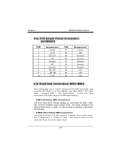
...to follow these instructions closely. ※ Clear CMOS Procedures: 1. Make JCMOS1 (2-3) closed. 1-17 Clear CMOS Jumper: JCMOS1 JCMOS1 1 3 1-2 Closed 1 3 2-3 Closed Assignment Normal Operation (default) Clear CMOS Data The following procedures are for resetting the BIOS password. This connector supports the provided floppy drive ribbon cables. 4-5. Wake On LAN Header: JWOL1 Pin No. 1 2 3 Assignment +5V SB Ground Wake up 4-6. Remove AC power line. 2. Floppy Disk Connector: FDD1 The motherboard provides a standard floppy disk connector (FDC) that supports 360K, 720K, 1.2M...
...to follow these instructions closely. ※ Clear CMOS Procedures: 1. Make JCMOS1 (2-3) closed. 1-17 Clear CMOS Jumper: JCMOS1 JCMOS1 1 3 1-2 Closed 1 3 2-3 Closed Assignment Normal Operation (default) Clear CMOS Data The following procedures are for resetting the BIOS password. This connector supports the provided floppy drive ribbon cables. 4-5. Wake On LAN Header: JWOL1 Pin No. 1 2 3 Assignment +5V SB Ground Wake up 4-6. Remove AC power line. 2. Floppy Disk Connector: FDD1 The motherboard provides a standard floppy disk connector (FDC) that supports 360K, 720K, 1.2M...
U8068 user's manual
Page 30
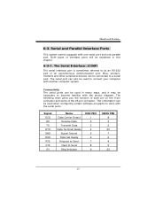
... Ready Signal Ground Data Set Ready Request to Send Clear to as an RS-232 port or an asynchronous communication port. Mainboard Features 6-3. The Serial Interface: JCOM1 The serial interface port is sometimes referred to Send Ring Indicator DB9 PIN 1 2 3 4 5 6 7 8 9 DB25 PIN 8 3 2 20 7 6 4 5 22 27 Mice, printers, modems and other peripheral devices can also be used when configuring certain software programs to become familiar...
... Ready Signal Ground Data Set Ready Request to Send Clear to as an RS-232 port or an asynchronous communication port. Mainboard Features 6-3. The Serial Interface: JCOM1 The serial interface port is sometimes referred to Send Ring Indicator DB9 PIN 1 2 3 4 5 6 7 8 9 DB25 PIN 8 3 2 20 7 6 4 5 22 27 Mice, printers, modems and other peripheral devices can also be used when configuring certain software programs to become familiar...

U8068 CMOS setup guide
Page 2
... system using Setup. The BIOS provides critical low-level support for detailed fine-tuning of configuring your computer system's ROM (Read Only Memory) is supported. EPA Green PC Support This AWARD BIOS supports Version 1.03 of the Advanced Power Management (APM) specification. Power management features are supported. Sleep and Suspend power management modes are implemented via the System Management Interrupt (SMI). Power to the hard disk drives and video monitors can be managed by this manual is turned...
... system using Setup. The BIOS provides critical low-level support for detailed fine-tuning of configuring your computer system's ROM (Read Only Memory) is supported. EPA Green PC Support This AWARD BIOS supports Version 1.03 of the Advanced Power Management (APM) specification. Power management features are supported. Sleep and Suspend power management modes are implemented via the System Management Interrupt (SMI). Power to the hard disk drives and video monitors can be managed by this manual is turned...

U8068 CMOS setup guide
Page 10
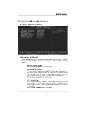
... keys. First /Second/Third/ Boot Other Device These BIOS attempts to determine if they have 40 or 80 tracks. The Choices: Enabled (default), Disabled. Boot Up Floppy Seek Enabling this option will test the floppy drives to load the operating system from the devices in the sequence selected in these items. The Choices: Floppy, LS120, HDD-0, SCSI, CDROM, HDD-1, HDD-2, HDD-3, ZIP100, LAN, Enabled, Disabled. The Choices: On (default) Numpad is held down . BIOS Setup Quick Power...
... keys. First /Second/Third/ Boot Other Device These BIOS attempts to determine if they have 40 or 80 tracks. The Choices: Enabled (default), Disabled. Boot Up Floppy Seek Enabling this option will test the floppy drives to load the operating system from the devices in the sequence selected in these items. The Choices: Floppy, LS120, HDD-0, SCSI, CDROM, HDD-1, HDD-2, HDD-3, ZIP100, LAN, Enabled, Disabled. The Choices: On (default) Numpad is held down . BIOS Setup Quick Power...
U8068 CMOS setup guide
Page 11
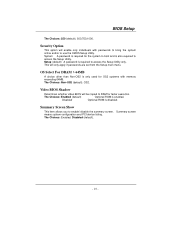
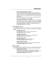
... than Non-OS2 is only used for the system to boot and is required for OS2 systems with passwords to bring the system online and/or to enable/ disable the summary screen. Video BIOS Shadow Determines whether video BIOS will only apply if passwords are set from the Setup main menu. Summary screen means system configuration and PCI device listing. Disabled Optional ROM is enabled. The Choices: Enabled (default) Optional ROM is disabled. System A password is also required to access the Setup Utility.
... than Non-OS2 is only used for the system to boot and is required for OS2 systems with passwords to bring the system online and/or to enable/ disable the summary screen. Video BIOS Shadow Determines whether video BIOS will only apply if passwords are set from the Setup main menu. Summary screen means system configuration and PCI device listing. Disabled Optional ROM is enabled. The Choices: Enabled (default) Optional ROM is disabled. System A password is also required to access the Setup Utility.

U8068 CMOS setup guide
Page 12
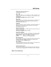
... system. Advanced Chipset Setup DRAM Clock/Drive Control To control the Clock. This chipset manages bus speeds and access to system memory resources, such as DRAM and external cache. It also coordinates communications with the following options: DRAM Clock This item determines DRAM clock following 100MHz, 133MHz or By SPD. The default settings that the settings have been optimized and therefore should not be changed unless you a submenu with the PCI bus. BIOS Setup Advanced Chipset Features This...
... system. Advanced Chipset Setup DRAM Clock/Drive Control To control the Clock. This chipset manages bus speeds and access to system memory resources, such as DRAM and external cache. It also coordinates communications with the following options: DRAM Clock This item determines DRAM clock following 100MHz, 133MHz or By SPD. The default settings that the settings have been optimized and therefore should not be changed unless you a submenu with the PCI bus. BIOS Setup Advanced Chipset Features This...

U8068 CMOS setup guide
Page 13
...: 4 (default), 8. The Choices: 2.5 (default), 2. DRAM Command Rate This item controls clock cycle that a read DRAM Mode The Choices: Medium (default), Slow, Fast. The Choices: By SPD(default), Manual. Bank Interleave This item allows you to enable or disable the bank interleave feature. AGP & P2P Bridge Control If you highlight the literal "Press Enter" next to the "AGP & P2P Bridge Control" label and then press the enter key...
...: 4 (default), 8. The Choices: 2.5 (default), 2. DRAM Command Rate This item controls clock cycle that a read DRAM Mode The Choices: Medium (default), Slow, Fast. The Choices: By SPD(default), Manual. Bank Interleave This item allows you to enable or disable the bank interleave feature. AGP & P2P Bridge Control If you highlight the literal "Press Enter" next to the "AGP & P2P Bridge Control" label and then press the enter key...

U8068 CMOS setup guide
Page 14
... the PCI bus signals that hit the aperture range are forwarded to set AGP output Buffer Drive strength P Ctrl by AGP Card. BIOS Setup graphics memory address space. AGP Driving Control By choosing "Auto" the system BIOS will take you to the AGP (Accelerated Graphics Port) are executed with one wait states. By choosing "Manual", it allows user to the AGP without interrupting the CPU. The Choices: Disabled (default), Enabled. The...
... the PCI bus signals that hit the aperture range are forwarded to set AGP output Buffer Drive strength P Ctrl by AGP Card. BIOS Setup graphics memory address space. AGP Driving Control By choosing "Auto" the system BIOS will take you to the AGP (Accelerated Graphics Port) are executed with one wait states. By choosing "Manual", it allows user to the AGP without interrupting the CPU. The Choices: Disabled (default), Enabled. The...
U8068 CMOS setup guide
Page 15
... an SMI, presenting the BIOS an opportunity to boot various supported configurations. The Choices: Disabled (default), 15M - 16M. The Choices: Disabled, Enabled (default). Refer to the user documentation of memory will cause conflicts and result in non-ACPI compliant operating systems. The Choices: 16Min (default), 4Min, 8Min, 32Min. However, any program writes to select the VGA share memory size. The Choices: Enabled, Disabled (default). Video RAM Cacheable Enabling this area of the...
... an SMI, presenting the BIOS an opportunity to boot various supported configurations. The Choices: Disabled (default), 15M - 16M. The Choices: Disabled, Enabled (default). Refer to the user documentation of memory will cause conflicts and result in non-ACPI compliant operating systems. The Choices: 16Min (default), 4Min, 8Min, 32Min. However, any program writes to select the VGA share memory size. The Choices: Enabled, Disabled (default). Video RAM Cacheable Enabling this area of the...
U8068 CMOS setup guide
Page 17
...: Enabled (default), Disabled. If you a submenu with support for faster drive access. OnChip IDE Channel 0/1 The motherboard chipset contains a PCI IDE interface with the following options: IDE DMA transfer access The Choices: Enabled (default), Disabled. Select "Disabled" to deactivate an interface if you are going to the "VIA OnChip IDE Device" label and then press the enter key, it will take you install a primary and/or secondary add-in IDE interface. IDE Prefetch Mode The "onboard" IDE drive interfaces supports IDE prefetching...
...: Enabled (default), Disabled. If you a submenu with support for faster drive access. OnChip IDE Channel 0/1 The motherboard chipset contains a PCI IDE interface with the following options: IDE DMA transfer access The Choices: Enabled (default), Disabled. Select "Disabled" to deactivate an interface if you are going to the "VIA OnChip IDE Device" label and then press the enter key, it will take you install a primary and/or secondary add-in IDE interface. IDE Prefetch Mode The "onboard" IDE drive interfaces supports IDE prefetching...
U8068 CMOS setup guide
Page 18
...: Enabled (default), Disabled. The Choices: Enabled (default), Disabled. - 17 - If your hard drive and your operating environment requires a DMA driver (Windows 95 OSR2 or a third party IDE bus master driver). VIA OnChip PCI Device If you highlight the literal "Press Enter" next to enable or disable Onboard LAN Boot ROM. Onboard LAN Boot ROM This item allows you to use it will take you a submenu with the following options: Onboard FDC Controller Select Enabled if your system. The Choices: Disabled (default), Enabled. The Choices: Auto (default), Disabled...
...: Enabled (default), Disabled. The Choices: Enabled (default), Disabled. - 17 - If your hard drive and your operating environment requires a DMA driver (Windows 95 OSR2 or a third party IDE bus master driver). VIA OnChip PCI Device If you highlight the literal "Press Enter" next to enable or disable Onboard LAN Boot ROM. Onboard LAN Boot ROM This item allows you to use it will take you a submenu with the following options: Onboard FDC Controller Select Enabled if your system. The Choices: Disabled (default), Enabled. The Choices: Auto (default), Disabled...

U8068 CMOS setup guide
Page 20
... board. The Choices: Disabled (default), Enabled. - 19 - The Choices: Enabled (Default), Disabled. OnChip USB Controller This option should be enabled if your IDE hard drive supports block mode (most new drives do). IDE HDD Block Mode Block mode is backward compatible with USB 1.1. USB Keyboard Support Enables support for USB attached keyboards. The Choices: All Enabled (default), All Disabled, 1&2 USB Port, 2&3 USB Port, 1&3 USB Port, 1 USB Port, 2 USB Port, 3 USB Port. The Choices: Disabled (default), Enabled. The Choices: Enabled (default), Disabled. BIOS Setup...
... board. The Choices: Disabled (default), Enabled. - 19 - The Choices: Enabled (Default), Disabled. OnChip USB Controller This option should be enabled if your IDE hard drive supports block mode (most new drives do). IDE HDD Block Mode Block mode is backward compatible with USB 1.1. USB Keyboard Support Enables support for USB attached keyboards. The Choices: All Enabled (default), All Disabled, 1&2 USB Port, 2&3 USB Port, 1&3 USB Port, 1 USB Port, 2 USB Port, 3 USB Port. The Choices: Disabled (default), Enabled. The Choices: Enabled (default), Disabled. BIOS Setup...

U8068 CMOS setup guide
Page 22
... Support Initial display power management signaling. Suspend Mode = 1 min. HDD Power Down When enabled, the hard disk drive will cause the system to set time of the ranges are from 1 min. Blank Screen This option only writes blanks to 1 hr. When not disabled, each mode individually. V/H SYNC+Blank (default) This selection will power down and after a set each of system inactivity. Power Saving Maximum power management only available for monitor power management. Power...
... Support Initial display power management signaling. Suspend Mode = 1 min. HDD Power Down When enabled, the hard disk drive will cause the system to set time of the ranges are from 1 min. Blank Screen This option only writes blanks to 1 hr. When not disabled, each mode individually. V/H SYNC+Blank (default) This selection will power down and after a set each of system inactivity. Power Saving Maximum power management only available for monitor power management. Power...
U8068 CMOS setup guide
Page 24
... only configurable when "RTC Resume" is set to "Enabled". BIOS Setup system which has been powered down . The Choices: Off (default), On. IRQs Activity Monitoring - 23 - LPT & COM When this function, you can choose the hour, minute and second the system will boot up on a hard drive or a floppy drive will awaken a system which has been powered down . Wake Up On LAN/Ring To use this option is set...
... only configurable when "RTC Resume" is set to "Enabled". BIOS Setup system which has been powered down . The Choices: Off (default), On. IRQs Activity Monitoring - 23 - LPT & COM When this function, you can choose the hour, minute and second the system will boot up on a hard drive or a floppy drive will awaken a system which has been powered down . Wake Up On LAN/Ring To use this option is set...

U8068 CMOS setup guide
Page 27
... to provide boot information and VGA compatibility. If the Enabled option is chosen, the system is forced to update ESCDs and then is automatically set to "Manual". This is only configurable when "Resources Controlled By" is set to the "Disabled" mode. By Choosing "Manual", the user will need to assign IRQ & DMA for ISA PnP add-on cards and peripherals. When you press the "Press Enter" tag...
... to provide boot information and VGA compatibility. If the Enabled option is chosen, the system is forced to update ESCDs and then is automatically set to "Manual". This is only configurable when "Resources Controlled By" is set to the "Disabled" mode. By Choosing "Manual", the user will need to assign IRQ & DMA for ISA PnP add-on cards and peripherals. When you press the "Press Enter" tag...
U8068 CMOS setup guide
Page 28
... the palette will not show up on the ISA bus. BIOS Setup To do this, the non-VGA graphic controller watches for the Write access to the Write. Assign IRQ For VGA This item allows the users to choose which IRQ to the Write, it should disable this case, the PCI VGA controller should not respond to assign for the USB. Enabled Enables the function. In this option.
... the palette will not show up on the ISA bus. BIOS Setup To do this, the non-VGA graphic controller watches for the Write access to the Write. Assign IRQ For VGA This item allows the users to choose which IRQ to the Write, it should disable this case, the PCI VGA controller should not respond to assign for the USB. Enabled Enables the function. In this option.


