
TForce4 U user's manual
Page 1
... limits of a Class B digital device, pursuant to the contents here and specially disclaims any implied warranties of merchantability or fitness for any party beforehand. Biostar T-Series TForce4/ TForce4 U FCC Information and Copyright This equipment has been tested and found in a residential installation. Further the vendor reserves the right to revise this publication, in...
... limits of a Class B digital device, pursuant to the contents here and specially disclaims any implied warranties of merchantability or fitness for any party beforehand. Biostar T-Series TForce4/ TForce4 U FCC Information and Copyright This equipment has been tested and found in a residential installation. Further the vendor reserves the right to revise this publication, in...
TForce4 U user's manual
Page 2
... B. Know your CPU version ...4 2.3 PERIPHERALS ...5 A. Card and I CHAPTER 1: INTRODUCTION ...1 1.1 MOTHERBOARD FEATURES ...1 1.2 LAYOUT AND COMPONENTS ...2 CHAPTER 2: HARDWARE INSTALLATIONS ...3 2.1 CPU ASSEMBLY ...3 A. DDR Installation Notice...4 D. DDR Modules ...4 B. Biostar T-Series TForce4/ TForce4 U PACKAGE CHECKLIST ...I /O Slots:...5 B. About FAN Headers ...3 2.2 SYSTEM MEMORY...4 A. CPU Overheated...14 4.3 TROUBLESHOOTING ...15 GERMAN...16 FRENCH ...17 ITALIAN ...18 SPANISH...19 PORTUGUESE ...20 POLAND...21...
... B. Know your CPU version ...4 2.3 PERIPHERALS ...5 A. Card and I CHAPTER 1: INTRODUCTION ...1 1.1 MOTHERBOARD FEATURES ...1 1.2 LAYOUT AND COMPONENTS ...2 CHAPTER 2: HARDWARE INSTALLATIONS ...3 2.1 CPU ASSEMBLY ...3 A. DDR Installation Notice...4 D. DDR Modules ...4 B. Biostar T-Series TForce4/ TForce4 U PACKAGE CHECKLIST ...I /O Slots:...5 B. About FAN Headers ...3 2.2 SYSTEM MEMORY...4 A. CPU Overheated...14 4.3 TROUBLESHOOTING ...15 GERMAN...16 FRENCH ...17 ITALIAN ...18 SPANISH...19 PORTUGUESE ...20 POLAND...21...
TForce4 U user's manual
Page 3
...transfer rates up to 400Mb/s. Supports PIO mode 0~4, Block Mode and Ultra DMA 33/66/100/133 bus master mode. 1 TForce4/ TForce4 U AC'97 Audio Sound Codec Chip: ALC850, supports 8 channels audio output. Supports NVIDIA StreamThru technology Isochronous controller ...from intruders by filtering unauthorized traffic. NVIDIA Active Armor (Only for TForce4. Dimensions ATX Form Factor: 23.4cm (W) x 29.35cm (L) Main Memory Supports Dual Channel DDR. Supports DDR333 and DDR400. Biostar T-Series Chapter 1: Introduction 1.1 MOTHERBOARD FEATURES CPU Supports Socket 939...
...transfer rates up to 400Mb/s. Supports PIO mode 0~4, Block Mode and Ultra DMA 33/66/100/133 bus master mode. 1 TForce4/ TForce4 U AC'97 Audio Sound Codec Chip: ALC850, supports 8 channels audio output. Supports NVIDIA StreamThru technology Isochronous controller ...from intruders by filtering unauthorized traffic. NVIDIA Active Armor (Only for TForce4. Dimensions ATX Form Factor: 23.4cm (W) x 29.35cm (L) Main Memory Supports Dual Channel DDR. Supports DDR333 and DDR400. Biostar T-Series Chapter 1: Introduction 1.1 MOTHERBOARD FEATURES CPU Supports Socket 939...
TForce4 U user's manual
Page 4
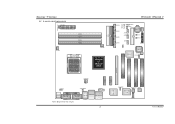
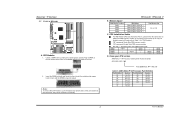
Biostar T-Series 1.2 LAYOUT AND COMPONENTS JATXPWR1 JDDR_0V>3V JCFAN1 DIMM3 DIMM1 DIMM4 DIMM2 Socket 939 JNBFAN1 nForce4 or nForce4 Ultra IDE2 IDE1 LED_D1 LED_D2 LED_DIMM LED_5SB FDD1 TForce4/ TForce4 U JSATA4 JSATA3 JSATA2 JSATA1 JCMOS1 JUSBV1 JUSB3 JUSB2 JUSB1 JCI1 JSFAN1 BAT1 RSTSW PWRSW JPANEL1 BIOS Super I/O JSFAN2 J1394A1 PCI-EX16 XGP1 JATXPWR2 JKBMSV1 J1394_USBV1...
Biostar T-Series 1.2 LAYOUT AND COMPONENTS JATXPWR1 JDDR_0V>3V JCFAN1 DIMM3 DIMM1 DIMM4 DIMM2 Socket 939 JNBFAN1 nForce4 or nForce4 Ultra IDE2 IDE1 LED_D1 LED_D2 LED_DIMM LED_5SB FDD1 TForce4/ TForce4 U JSATA4 JSATA3 JSATA2 JSATA1 JCMOS1 JUSBV1 JUSB3 JUSB2 JUSB1 JCI1 JSFAN1 BAT1 RSTSW PWRSW JPANEL1 BIOS Super I/O JSFAN2 J1394A1 PCI-EX16 XGP1 JATXPWR2 JKBMSV1 J1394_USBV1...
TForce4 U user's manual
Page 5
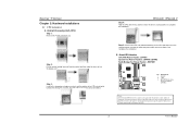
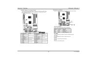
... 3 User's Manual Step 2: Pull the socket locking lever out from the socket and then raise the lever up to complete the installation. TForce4/ TForce4 U Step 4: Hold the CPU down firmly, and then lower the lever to locked position to a 90-degree angle. Step 5: Put the... on socket, and the golden dot on the retention frame. This completes the installation. When connecting with Smart Fan Control utilities. B. Biostar T-Series Chapter 2: Hardware Installations 2.1 CPU ASSEMBLY A. Step 3: Look for the triangular cut edge. Central Processing Unit (CPU) Step 1: Remove ...
... 3 User's Manual Step 2: Pull the socket locking lever out from the socket and then raise the lever up to complete the installation. TForce4/ TForce4 U Step 4: Hold the CPU down firmly, and then lower the lever to locked position to a 90-degree angle. Step 5: Put the... on socket, and the golden dot on the retention frame. This completes the installation. When connecting with Smart Fan Control utilities. B. Biostar T-Series Chapter 2: Hardware Installations 2.1 CPU ASSEMBLY A. Step 3: Look for the triangular cut edge. Central Processing Unit (CPU) Step 1: Remove ...
TForce4 U user's manual
Page 6
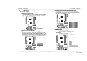
... the DDR modules, push the ejector tabs at both sides of the slot outward at the same time, and pull the modules out vertically. TForce4/ TForce4 U B. E, please follow the table below to Table 1 for CPU Revision) "SS" represents Single Side DDR memory module. Biostar T-Series 2.2 SYSTEM MEMORY DIMM3 DIMM1 DIMM4 DIMM2 Codec BIOS A.
... the DDR modules, push the ejector tabs at both sides of the slot outward at the same time, and pull the modules out vertically. TForce4/ TForce4 U B. E, please follow the table below to Table 1 for CPU Revision) "SS" represents Single Side DDR memory module. Biostar T-Series 2.2 SYSTEM MEMORY DIMM3 DIMM1 DIMM4 DIMM2 Codec BIOS A.
TForce4 U user's manual
Page 7
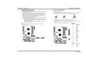
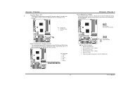
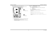
... This connector supports the provided floppy drive ribbon cables. PCI Express 1.0a compliant. - Maximum bandwidth is up to 250MB/s per direction. Biostar T-Series 2.3 PERIPHERALS A. The IDE connectors can connect a master and a slave drive, so you can connect up to four hard disk...The motherboard has two 32-bit Enhanced PCI IDE Controllers that supports 360K, 720K, 1.2M, 1.44M and 2.88M floppy disk types. TForce4/ TForce4 U Peripheral Component Interconnect Slots: PCI1~PCI3 This motherboard is a bus standard for Peripheral Component Interconnect, and it is equipped with 3 ...
... This connector supports the provided floppy drive ribbon cables. PCI Express 1.0a compliant. - Maximum bandwidth is up to 250MB/s per direction. Biostar T-Series 2.3 PERIPHERALS A. The IDE connectors can connect a master and a slave drive, so you can connect up to four hard disk...The motherboard has two 32-bit Enhanced PCI IDE Controllers that supports 360K, 720K, 1.2M, 1.44M and 2.88M floppy disk types. TForce4/ TForce4 U Peripheral Component Interconnect Slots: PCI1~PCI3 This motherboard is a bus standard for Peripheral Component Interconnect, and it is equipped with 3 ...
TForce4 U user's manual
Page 8
... adapter. 2. Connectors and Headers: How to setup Jumpers The illustration shows how to "http://www.biostar.com.tw" for more detailed information about XGP compatible AGP cards. XGP1 Codec BIOS TForce4/ TForce4 U B. If the onboard VGA driver can be removed completely, and to connect 24-pin power ... the jumper is "closed ATX Power Source Connectors: JATXPWR1/JATXPWR2 JATXPWR1 allows user to solve this problem, please follow the steps below: 1. Biostar T-Series Xtreme Graphics Port Slot: XGP1 This XGP (Xtreme Graphics Port) slot is "open". To install the system with an add-on AGP...
... adapter. 2. Connectors and Headers: How to setup Jumpers The illustration shows how to "http://www.biostar.com.tw" for more detailed information about XGP compatible AGP cards. XGP1 Codec BIOS TForce4/ TForce4 U B. If the onboard VGA driver can be removed completely, and to connect 24-pin power ... the jumper is "closed ATX Power Source Connectors: JATXPWR1/JATXPWR2 JATXPWR1 allows user to solve this problem, please follow the steps below: 1. Biostar T-Series Xtreme Graphics Port Slot: XGP1 This XGP (Xtreme Graphics Port) slot is "open". To install the system with an add-on AGP...
TForce4 U user's manual
Page 9
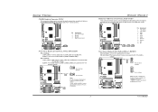
... support this function "Power-on system via USB device," "J1394_USBV1/JUSBV1" jumper cap should be placed on Pin 2-3 individually. 31 Codec BIOS 7 TForce4/ TForce4 U Headers for USB ports at PC front panel, and also can be placed on Pin 2-3. JUSBV1: +5V for PS/2 keyboard and mouse. ...J1394_USBV1: +5V for USB Ports at Front Panel: JUSB1~JUSB3 This connector allows user to connect additional USB cables at J1394_USB1 and JUSBLAN1. Biostar T-Series CD-ROM Audio-in Connector: JCDIN1 This connector allows user to connect the audio source from a variety of devices, like USB card...
... support this function "Power-on system via USB device," "J1394_USBV1/JUSBV1" jumper cap should be placed on Pin 2-3 individually. 31 Codec BIOS 7 TForce4/ TForce4 U Headers for USB ports at PC front panel, and also can be placed on Pin 2-3. JUSBV1: +5V for PS/2 keyboard and mouse. ...J1394_USBV1: +5V for USB Ports at Front Panel: JUSB1~JUSB3 This connector allows user to connect additional USB cables at J1394_USB1 and JUSBLAN1. Biostar T-Series CD-ROM Audio-in Connector: JCDIN1 This connector allows user to connect the audio source from a variety of devices, like USB card...
TForce4 U user's manual
Page 10
... Speaker-out Left 11 Right line-in (optional) 12 Right line-in (optional) Codec BIOS 13 Left line-in (optional) 14 Left line-in (optional) 8 TForce4/ TForce4 U Power Source Header for 1394 Chip: J1394PWR1 3 1 Pin 1-2 Close: +3.3V for 1394 chipset (default). 3 1 J1394PWR1 31 Pin 2-3 Close: +3.3V SB... user to connect the front 1394 port for 1394 chipset. It will allow user to connect the PCI bracket SPDIF output header. Biostar T-Series Digital Audio-out Connector: JSPDIF_OUT This connector allows users to connect with the front audio output headers on back panel audio ...
... Speaker-out Left 11 Right line-in (optional) 12 Right line-in (optional) Codec BIOS 13 Left line-in (optional) 14 Left line-in (optional) 8 TForce4/ TForce4 U Power Source Header for 1394 Chip: J1394PWR1 3 1 Pin 1-2 Close: +3.3V for 1394 chipset (default). 3 1 J1394PWR1 31 Pin 2-3 Close: +3.3V SB... user to connect the front 1394 port for 1394 chipset. It will allow user to connect the PCI bracket SPDIF output header. Biostar T-Series Digital Audio-out Connector: JSPDIF_OUT This connector allows users to connect with the front audio output headers on back panel audio ...
TForce4 U user's manual
Page 11
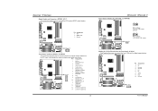
...Set the jumper to "Pin 2-3 Close". 3. JSATA1 JSATA2 JSATA3 JSATA4 7 41 Pin Assignment 1 Ground 2 TX+ 3 TX4 Ground 5 RX6 RX+ 7 Ground Codec BIOS TForce4/ TForce4 U Clear CMOS Header: JCMOS1 By placing the jumper on pin 2-3, it will record to the CMOS and show the message on the AC. 6. Wait for... five seconds. 4. Set the jumper to "Pin 1-2 Close". 5. Biostar T-Series Case Open Header: JCI1 This connector allows system to monitor PC case open signal 2 Ground JCI1 12 Codec BIOS Serial ATA Connectors: JSATA1~JSATA4...
...Set the jumper to "Pin 2-3 Close". 3. JSATA1 JSATA2 JSATA3 JSATA4 7 41 Pin Assignment 1 Ground 2 TX+ 3 TX4 Ground 5 RX6 RX+ 7 Ground Codec BIOS TForce4/ TForce4 U Clear CMOS Header: JCMOS1 By placing the jumper on pin 2-3, it will record to the CMOS and show the message on the AC. 6. Wait for... five seconds. 4. Set the jumper to "Pin 1-2 Close". 5. Biostar T-Series Case Open Header: JCI1 This connector allows system to monitor PC case open signal 2 Ground JCI1 12 Codec BIOS Serial ATA Connectors: JSATA1~JSATA4...
TForce4 U user's manual
Page 12
... Switch button. PWRSW: This is activated normally. LED_5SB: This LED indicates the system is an on-board Reset button. 10 User's Manual Biostar T-Series JPANEL1: Header for Power-on. TForce4/ TForce4 U LED Indicators and Buttons There are 4 LED indicators on the motherboard to connect the PC case's front panel switch functions. RSTSW: This...
... Switch button. PWRSW: This is activated normally. LED_5SB: This LED indicates the system is an on-board Reset button. 10 User's Manual Biostar T-Series JPANEL1: Header for Power-on. TForce4/ TForce4 U LED Indicators and Buttons There are 4 LED indicators on the motherboard to connect the PC case's front panel switch functions. RSTSW: This...
TForce4 U user's manual
Page 13
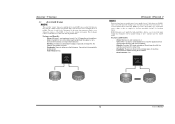
... RAID arrays: RAID 0: RAID 0 defines a disk striping scheme that your DDR supports up to 3V. (Consulting your DDR supplier) TForce4/ TForce4 U Chapter 3: NVIDIA RAID Functions 3.1 OPERATION SYSTEM Supports Windows XP Home/Professional Edition, and Windows 2000 Professional. 3.2 RAID ARRAYS NVRAID ...supports the following types of different sizes in RAID 0 and RAID 1. Biostar T-Series Header for Memory Voltage Overclocking: JDDR_OV>3V When processing Memory Voltage Overclocking, please place the jumper to one large disk...
... RAID arrays: RAID 0: RAID 0 defines a disk striping scheme that your DDR supports up to 3V. (Consulting your DDR supplier) TForce4/ TForce4 U Chapter 3: NVIDIA RAID Functions 3.1 OPERATION SYSTEM Supports Windows XP Home/Professional Edition, and Windows 2000 Professional. 3.2 RAID ARRAYS NVRAID ...supports the following types of different sizes in RAID 0 and RAID 1. Biostar T-Series Header for Memory Voltage Overclocking: JDDR_OV>3V When processing Memory Voltage Overclocking, please place the jumper to one large disk...
TForce4 U user's manual
Page 14
The size of each block is determined by the stripe size parameter, which you set during drive rebuilds. Fault Tolerance: Yes. TForce4/ TForce4 U RAID 1: Every read and write is ideal for parity. Drawbacks: Does not deliver any other drive. Drawbacks...; Drives: Minimum 2, and maximum is 2. Uses: RAID 1 is actually carried out in parallel across multiple drives in a RAID 0 array system. Biostar T-Series 3.3 HOW RAID WORKS RAID 0: The controller "stripes" data across 2 disk drives in a RAID 1 array system. No capacity loss penalty for small...
The size of each block is determined by the stripe size parameter, which you set during drive rebuilds. Fault Tolerance: Yes. TForce4/ TForce4 U RAID 1: Every read and write is ideal for parity. Drawbacks: Does not deliver any other drive. Drawbacks...; Drives: Minimum 2, and maximum is 2. Uses: RAID 1 is actually carried out in parallel across multiple drives in a RAID 0 array system. Biostar T-Series 3.3 HOW RAID WORKS RAID 0: The controller "stripes" data across 2 disk drives in a RAID 1 array system. No capacity loss penalty for small...
TForce4 U user's manual
Page 15
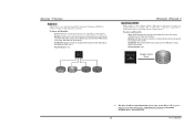
...information, please refer to the Driver CD, or go to http://www.nvidia.com/page/pg_20011106217193.html to make one big drive. - Biostar T-Series RAID 0+1: RAID 0 drives can be simultaneously used with other RAID levels in a RAID 0+1 solution for improved performance plus ... of Disks". Features and Benefits - Block 1 Block 3 Block 5 Block 2 Block 4 Block 6 Block 1 Block 3 Block 5 Block 2 Block 4 Block 6 TForce4/ TForce4 U Spanning (JBOD): JBOD stands for spare disks. - Features and Benefits - Resulting in an array, and allows for "Just a Bunch of the difficulty in using ...
...information, please refer to the Driver CD, or go to http://www.nvidia.com/page/pg_20011106217193.html to make one big drive. - Biostar T-Series RAID 0+1: RAID 0 drives can be simultaneously used with other RAID levels in a RAID 0+1 solution for improved performance plus ... of Disks". Features and Benefits - Block 1 Block 3 Block 5 Block 2 Block 4 Block 6 Block 1 Block 3 Block 5 Block 2 Block 4 Block 6 TForce4/ TForce4 U Spanning (JBOD): JBOD stands for spare disks. - Features and Benefits - Resulting in an array, and allows for "Just a Bunch of the difficulty in using ...
TForce4 U user's manual
Page 16
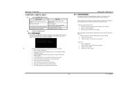
Download the Flash Utility "AWDFLASH.exe" from Biostar website. 4. TForce4/ TForce4 U B. CPU fan is placed evenly with the CPU surface. 2. Remove the power cord from power supply for a few seconds. 3. If the following message is over ... sound CPU overheated System will shut down automatically after boot-up to DOS prompt. 7. Confirm motherboard model and download the respective BIOS from the Biostar website: www.biostar.com.tw 3. System will work properly. Power on again. Wait for a few seconds. 2. In this case, please follow the steps below to relieve ...
Download the Flash Utility "AWDFLASH.exe" from Biostar website. 4. TForce4/ TForce4 U B. CPU fan is placed evenly with the CPU surface. 2. Remove the power cord from power supply for a few seconds. 3. If the following message is over ... sound CPU overheated System will shut down automatically after boot-up to DOS prompt. 7. Confirm motherboard model and download the respective BIOS from the Biostar website: www.biostar.com.tw 3. System will work properly. Power on again. Wait for a few seconds. 2. In this case, please follow the steps below to relieve ...
TForce4 U user's manual
Page 17
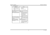
...extremely important. Cannot boot system after installing second hard drive. 1. Call the drive manufacturers for compatibility with other drives. 15 TForce4/ TForce4 U User's Manual inside power supply does not 2. snaps into place. Check cable running from optical drive. 1. System only ...the on, power indicator lights are lit, and DIMM, press down at all 1. Back up the hard drive is in ; Biostar T-Series 4.3 TROUBLESHOOTING Problem Solution 1. Contact technical support. 2. System inoperative. All hard disks are securely plugged in setup. Review system...
...extremely important. Cannot boot system after installing second hard drive. 1. Call the drive manufacturers for compatibility with other drives. 15 TForce4/ TForce4 U User's Manual inside power supply does not 2. snaps into place. Check cable running from optical drive. 1. System only ...the on, power indicator lights are lit, and DIMM, press down at all 1. Back up the hard drive is in ; Biostar T-Series 4.3 TROUBLESHOOTING Problem Solution 1. Contact technical support. 2. System inoperative. All hard disks are securely plugged in setup. Review system...


