
TForce4 U user's manual
Page 1
... harmful interference in a residential installation. All the brand and product names are designed to the contents here and specially disclaims any implied warranties of their respective companies. Biostar T-Series TForce4/ TForce4 U FCC Information and Copyright This equipment has been tested and found in this user's manual. PACKAGE CHECKLIST FDD Cable x 1 HDD Cable x 1 User's Manual x 1 Overclock Guide x 1 Serial ATA Cable x 2 Fully Setup Driver CD x 1 Rear I/O Panel for any party beforehand.
... harmful interference in a residential installation. All the brand and product names are designed to the contents here and specially disclaims any implied warranties of their respective companies. Biostar T-Series TForce4/ TForce4 U FCC Information and Copyright This equipment has been tested and found in this user's manual. PACKAGE CHECKLIST FDD Cable x 1 HDD Cable x 1 User's Manual x 1 Overclock Guide x 1 Serial ATA Cable x 2 Fully Setup Driver CD x 1 Rear I/O Panel for any party beforehand.
TForce4 U user's manual
Page 2
......14 4.3 TROUBLESHOOTING ...15 GERMAN...16 FRENCH ...17 ITALIAN ...18 SPANISH...19 PORTUGUESE ...20 POLAND...21 RUSSIAN ...22 ARABIC ...23 JAPANESE ...24 ii User's Manual Memory Space...4 C. About FAN Headers ...3 2.2 SYSTEM MEMORY...4 A. Know your CPU version ...4 2.3 PERIPHERALS ...5 A. Connectors and Headers:...6 CHAPTER 3: NVIDIA RAID FUNCTIONS ...11 3.1 OPERATION SYSTEM ...11 3.2 RAID ARRAYS ...11 3.3 HOW RAID WORKS ...12 CHAPTER 4: USEFUL HELP...14 4.1 AWARD BIOS BEEP CODE...14 4.2 EXTRA INFORMATION ...14 A. Biostar T-Series TForce4/ TForce4 U PACKAGE...
......14 4.3 TROUBLESHOOTING ...15 GERMAN...16 FRENCH ...17 ITALIAN ...18 SPANISH...19 PORTUGUESE ...20 POLAND...21 RUSSIAN ...22 ARABIC ...23 JAPANESE ...24 ii User's Manual Memory Space...4 C. About FAN Headers ...3 2.2 SYSTEM MEMORY...4 A. Know your CPU version ...4 2.3 PERIPHERALS ...5 A. Connectors and Headers:...6 CHAPTER 3: NVIDIA RAID FUNCTIONS ...11 3.1 OPERATION SYSTEM ...11 3.2 RAID ARRAYS ...11 3.3 HOW RAID WORKS ...12 CHAPTER 4: USEFUL HELP...14 4.1 AWARD BIOS BEEP CODE...14 4.2 EXTRA INFORMATION ...14 A. Biostar T-Series TForce4/ TForce4 U PACKAGE...
TForce4 U user's manual
Page 3
... by filtering unauthorized traffic. AMD 64 architecture enables simultaneous 32 and 64 bit computing. Maximum memory space is optional.) 4 USB 2.0 Ports. 6 audio ports support 8 channels audio-out facilities. Environment Control initiatives, H/W Monitor Fan Speed Controller ITE's "Smart Guardian" function IDE 2 on-board connectors support 4 IDE disk drives. Supports PIO mode 0~4, Block Mode and Ultra DMA 33/66/100/133 bus master mode. 1 TForce4/ TForce4 U AC'97 Audio Sound Codec Chip: ALC850, supports 8 channels audio output. NVIDIA Active Armor...
... by filtering unauthorized traffic. AMD 64 architecture enables simultaneous 32 and 64 bit computing. Maximum memory space is optional.) 4 USB 2.0 Ports. 6 audio ports support 8 channels audio-out facilities. Environment Control initiatives, H/W Monitor Fan Speed Controller ITE's "Smart Guardian" function IDE 2 on-board connectors support 4 IDE disk drives. Supports PIO mode 0~4, Block Mode and Ultra DMA 33/66/100/133 bus master mode. 1 TForce4/ TForce4 U AC'97 Audio Sound Codec Chip: ALC850, supports 8 channels audio output. NVIDIA Active Armor...
TForce4 U user's manual
Page 4
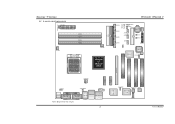
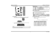
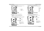
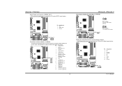
...-1 Giga LAN J1394PWR1 JSPDIF_OUT IEEE 1394 Chip JCDIN1 PCI1 PCI2 Codec PCI3 User's Manual Biostar T-Series 1.2 LAYOUT AND COMPONENTS JATXPWR1 JDDR_0V>3V JCFAN1 DIMM3 DIMM1 DIMM4 DIMM2 Socket 939 JNBFAN1 nForce4 or nForce4 Ultra IDE2 IDE1 LED_D1 LED_D2 LED_DIMM LED_5SB FDD1 TForce4/ TForce4 U JSATA4 JSATA3 JSATA2 JSATA1 JCMOS1 JUSBV1 JUSB3 JUSB2 JUSB1 JCI1 JSFAN1 BAT1 RSTSW PWRSW JPANEL1 BIOS Super I/O JSFAN2 J1394A1 PCI...
...-1 Giga LAN J1394PWR1 JSPDIF_OUT IEEE 1394 Chip JCDIN1 PCI1 PCI2 Codec PCI3 User's Manual Biostar T-Series 1.2 LAYOUT AND COMPONENTS JATXPWR1 JDDR_0V>3V JCFAN1 DIMM3 DIMM1 DIMM4 DIMM2 Socket 939 JNBFAN1 nForce4 or nForce4 Ultra IDE2 IDE1 LED_D1 LED_D2 LED_DIMM LED_5SB FDD1 TForce4/ TForce4 U JSATA4 JSATA3 JSATA2 JSATA1 JCMOS1 JUSBV1 JUSB3 JUSB2 JUSB1 JCI1 JSFAN1 BAT1 RSTSW PWRSW JPANEL1 BIOS Super I/O JSFAN2 J1394A1 PCI...
TForce4 U user's manual
Page 5
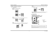
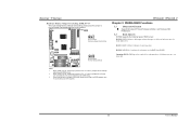
... angle. Connect the CPU FAN power cable into the JCFAN1. About FAN Headers CPU FAN Power Header: JCFAN1 System Fan Power Headers: JSFAN1/JSFAN2 North Bridge Fan Power Header: JNBFAN1 JCFAN1 31 JNBFAN1 1 3 JSFAN2 1 3 Codec BIOS JSFAN1 31 Pin Assignment 1 Ground 2 +12V 3 FAN RPM rate sense (Does not support JSFAN2.) Note: JCFAN1and JNBFAN1 reserve system cooling fan with wires onto connectors, please note that the red wire is the positive and should be connected to pin#2, and...
... angle. Connect the CPU FAN power cable into the JCFAN1. About FAN Headers CPU FAN Power Header: JCFAN1 System Fan Power Headers: JSFAN1/JSFAN2 North Bridge Fan Power Header: JNBFAN1 JCFAN1 31 JNBFAN1 1 3 JSFAN2 1 3 Codec BIOS JSFAN1 31 Pin Assignment 1 Ground 2 +12V 3 FAN RPM rate sense (Does not support JSFAN2.) Note: JCFAN1and JNBFAN1 reserve system cooling fan with wires onto connectors, please note that the red wire is the positive and should be connected to pin#2, and...
TForce4 U user's manual
Page 6
... break on the slot. 2. Star sign "*" represents leave the DIMM socket empty. C. Know your DDR memory module, or the system may not boot up or may not function properly. (Please refer to install your CPU version AMD Athlon™ 64 Processor Ordering Part Number Example ADA 3200 A E P 5 AP Part Definition: AP = Rev C0 Table 1: AMD Athlon™ 64 Processor Part Definition Part Definition AP AR...
... break on the slot. 2. Star sign "*" represents leave the DIMM socket empty. C. Know your DDR memory module, or the system may not boot up or may not function properly. (Please refer to install your CPU version AMD Athlon™ 64 Processor Ordering Part Number Example ADA 3200 A E P 5 AP Part Definition: AP = Rev C0 Table 1: AMD Athlon™ 64 Processor Part Definition Part Definition AP AR...
TForce4 U user's manual
Page 7
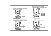
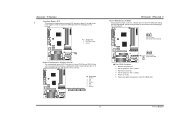
... Mode 0~4, Bus Master, and Ultra DMA 33/66/100/133 functionality. PCI1 PCI2 PCI3 Codec BIOS PCI-Express Slots PCI-EX16: - This connector supports the provided floppy drive ribbon cables. It has two HDD connectors IDE1 (primary) and IDE2 (secondary). PCI Express 1.0a compliant. - This PCI slot is designated as 32 bits. 2 34 Codec BIOS 1 33 Hard Disk Connectors: IDE1/IDE2 The motherboard has two 32-bit Enhanced PCI IDE Controllers that supports 360K, 720K, 1.2M, 1.44M and 2.88M floppy disk types...
... Mode 0~4, Bus Master, and Ultra DMA 33/66/100/133 functionality. PCI1 PCI2 PCI3 Codec BIOS PCI-Express Slots PCI-EX16: - This connector supports the provided floppy drive ribbon cables. It has two HDD connectors IDE1 (primary) and IDE2 (secondary). PCI Express 1.0a compliant. - This PCI slot is designated as 32 bits. 2 34 Codec BIOS 1 33 Hard Disk Connectors: IDE1/IDE2 The motherboard has two 32-bit Enhanced PCI IDE Controllers that supports 360K, 720K, 1.2M, 1.44M and 2.88M floppy disk types...
TForce4 U user's manual
Page 8
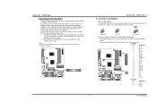
... Graphics Port Slot: XGP1 This XGP (Xtreme Graphics Port) slot is "closed ATX Power Source Connectors: JATXPWR1/JATXPWR2 JATXPWR1 allows user to connect 24-pin power connector on the ATX power supply. When the jumper cap is placed on AGP VGA card, the system will automatically set up jumpers. XGP1 Codec BIOS TForce4/ TForce4 U B. Connectors and Headers: How to setup Jumpers The illustration shows how to CPU power circuit. Disable onboard VGA utility under the operating system, and reboot PC. Note: Please go to install the driver...
... Graphics Port Slot: XGP1 This XGP (Xtreme Graphics Port) slot is "closed ATX Power Source Connectors: JATXPWR1/JATXPWR2 JATXPWR1 allows user to connect 24-pin power connector on the ATX power supply. When the jumper cap is placed on AGP VGA card, the system will automatically set up jumpers. XGP1 Codec BIOS TForce4/ TForce4 U B. Connectors and Headers: How to setup Jumpers The illustration shows how to CPU power circuit. Disable onboard VGA utility under the operating system, and reboot PC. Note: Please go to install the driver...
TForce4 U user's manual
Page 9
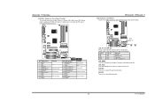
... powered with internal USB devices, like CD-ROM, DVD-ROM, PCI sound card, PCI TV tuner card etc.. JKBMSV1 1 3 1 3 Pin 1-2 Close (default) 1 3 Pin 2-3 Close Note: In order to support this function "Power-on system via keyboard and mouse", "JKBMSV1" jumper cap should be connected with +5V standby voltage. 3 1 Pin 1-2 Close (default) 3 1 J1394_USBV1 31 Pin 2-3 Close JUSBV1 Note: In order to connect the audio source from a variety of devices, like USB card reader. Codec BIOS User's Manual JUSBV1: Front USB headers (JUSB1/JUSB2/JUSB3) are powered...
... powered with internal USB devices, like CD-ROM, DVD-ROM, PCI sound card, PCI TV tuner card etc.. JKBMSV1 1 3 1 3 Pin 1-2 Close (default) 1 3 Pin 2-3 Close Note: In order to support this function "Power-on system via keyboard and mouse", "JKBMSV1" jumper cap should be connected with +5V standby voltage. 3 1 Pin 1-2 Close (default) 3 1 J1394_USBV1 31 Pin 2-3 Close JUSBV1 Note: In order to connect the audio source from a variety of devices, like USB card reader. Codec BIOS User's Manual JUSBV1: Front USB headers (JUSB1/JUSB2/JUSB3) are powered...
TForce4 U user's manual
Page 10
... Port at Front Panel: J1394A1 This header allows user to connect the PCI bracket SPDIF output header. Biostar T-Series Digital Audio-out Connector: JSPDIF_OUT This connector allows users to connect the front 1394 port for digital image devices. Pin Assignment 1 +5V 2 SPDIF OUT 3 Ground JSPDIF_OUT Codec BIOS 3 1 Front Panel Audio-out Header: JAUDIO2 This connector will disable the output on the PC case. Pin Assignment 1 MIC-in/ Stereo MIC-in R 2 Ground 3 Stereo MIC-in L 4 Audio power 5 Right line-out/ Speaker...
... Port at Front Panel: J1394A1 This header allows user to connect the PCI bracket SPDIF output header. Biostar T-Series Digital Audio-out Connector: JSPDIF_OUT This connector allows users to connect the front 1394 port for digital image devices. Pin Assignment 1 +5V 2 SPDIF OUT 3 Ground JSPDIF_OUT Codec BIOS 3 1 Front Panel Audio-out Header: JAUDIO2 This connector will disable the output on the PC case. Pin Assignment 1 MIC-in/ Stereo MIC-in R 2 Ground 3 Stereo MIC-in L 4 Audio power 5 Right line-out/ Speaker...
TForce4 U user's manual
Page 11
... pin 2-3, it allows user to restore the BIOS safe setting and the CMOS data, please carefully follow the procedures to avoid damaging the motherboard. 13 Pin 1-2 Close: Normal Operation (default). 13 JCMOS1 Pin 2-3 Close: Clear CMOS data. 1 3 Codec BIOS ※ Clear CMOS Procedures: 1. Set the jumper to "Pin 1-2 Close". 5. Biostar T-Series Case Open Header: JCI1 This connector allows system to monitor PC case open signal 2 Ground JCI1 12 Codec BIOS Serial ATA Connectors: JSATA1~JSATA4 The motherboard has an SATA Controller...
... pin 2-3, it allows user to restore the BIOS safe setting and the CMOS data, please carefully follow the procedures to avoid damaging the motherboard. 13 Pin 1-2 Close: Normal Operation (default). 13 JCMOS1 Pin 2-3 Close: Clear CMOS data. 1 3 Codec BIOS ※ Clear CMOS Procedures: 1. Set the jumper to "Pin 1-2 Close". 5. Biostar T-Series Case Open Header: JCI1 This connector allows system to monitor PC case open signal 2 Ground JCI1 12 Codec BIOS Serial ATA Connectors: JSATA1~JSATA4 The motherboard has an SATA Controller...
TForce4 U user's manual
Page 12
...Chipset Error LED_DIMM: This LED indicates the voltage of memory is activated normally. PWRSW: This is an on the motherboard to connect the PC case's front panel switch functions. TForce4/ TForce4 U LED Indicators and Buttons There are 4 LED indicators on -board Reset button. 10 User's Manual Biostar T-Series JPANEL1: Header for Front Panel Facilities This 24-pin connector includes Power-on diagnostics. Codec Pin Assignment 1 +5V 3 N/A 5 N/A 7 Speaker 9 HDD LED (+) 11 HDD LED (-) 13 Ground 15 Reset control 17 N/A 19 N/A 21 +5V 23 IRTX BIOS Function Speaker Connector Hard drive LED...
...Chipset Error LED_DIMM: This LED indicates the voltage of memory is activated normally. PWRSW: This is an on the motherboard to connect the PC case's front panel switch functions. TForce4/ TForce4 U LED Indicators and Buttons There are 4 LED indicators on -board Reset button. 10 User's Manual Biostar T-Series JPANEL1: Header for Front Panel Facilities This 24-pin connector includes Power-on diagnostics. Codec Pin Assignment 1 +5V 3 N/A 5 N/A 7 Speaker 9 HDD LED (+) 11 HDD LED (-) 13 Ground 15 Reset control 17 N/A 19 N/A 21 +5V 23 IRTX BIOS Function Speaker Connector Hard drive LED...
TForce4 U user's manual
Page 13
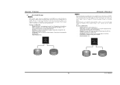
... NVRAID supports the following types of RAID arrays: RAID 0: RAID 0 defines a disk striping scheme that improves disk read and write times for combining drives of different sizes in RAID 0 and RAID 1. Spanning (JBOD): JBOD provides a method for many applications. Biostar T-Series Header for mirroring data. When "JDDR_OV>3V" jumper cap is placed on Pin 1-2, memory voltage will be fixed at 3.3V automatically, and can be adjusted under CMOS setup. 2. The Default setting...
... NVRAID supports the following types of RAID arrays: RAID 0: RAID 0 defines a disk striping scheme that improves disk read and write times for combining drives of different sizes in RAID 0 and RAID 1. Spanning (JBOD): JBOD provides a method for many applications. Biostar T-Series Header for mirroring data. When "JDDR_OV>3V" jumper cap is placed on Pin 1-2, memory voltage will be fixed at 3.3V automatically, and can be adjusted under CMOS setup. 2. The Default setting...
TForce4 U user's manual
Page 14
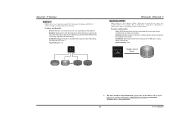
...TForce4/ TForce4 U RAID 1: Every read and write is ideal for the storage space of a hardware failure. RAID 1 provides a hot-standby copy of data if the active volume or drive is determined by the stripe size parameter, which you set based on a second redundant drive in the array. Should one drive fail, the controller switches to 6 or 8. RAID...1 Block 2 Block 3 12 User's Manual Biostar T-Series 3.3 HOW RAID WORKS RAID 0: The controller "stripes" data across 2 disk drives in a RAID 1 array system. The size of each block is corrupted or becomes unavailable because of one...
...TForce4/ TForce4 U RAID 1: Every read and write is ideal for the storage space of a hardware failure. RAID 1 provides a hot-standby copy of data if the active volume or drive is determined by the stripe size parameter, which you set based on a second redundant drive in the array. Should one drive fail, the controller switches to 6 or 8. RAID...1 Block 2 Block 3 12 User's Manual Biostar T-Series 3.3 HOW RAID WORKS RAID 0: The controller "stripes" data across 2 disk drives in a RAID 1 array system. The size of each block is corrupted or becomes unavailable because of one...
TForce4 U user's manual
Page 15
... 6 or 8, depending on a standard SCSI host bus adapter. Block 1 Block 3 Block 5 Block 2 Block 4 Block 6 Block 1 Block 3 Block 5 Block 2 Block 4 Block 6 TForce4/ TForce4 U Spanning (JBOD): JBOD stands for improved performance plus resiliency. Uses: JBOD works best if you have odd sized drives and you want to combine them to download NVIDIA nForce Tutorial Flash. 13 User's Manual Fault Tolerance: Yes. Resulting in...
... 6 or 8, depending on a standard SCSI host bus adapter. Block 1 Block 3 Block 5 Block 2 Block 4 Block 6 Block 1 Block 3 Block 5 Block 2 Block 4 Block 6 TForce4/ TForce4 U Spanning (JBOD): JBOD stands for improved performance plus resiliency. Uses: JBOD works best if you have odd sized drives and you want to combine them to download NVIDIA nForce Tutorial Flash. 13 User's Manual Fault Tolerance: Yes. Resulting in...
TForce4 U user's manual
Page 16
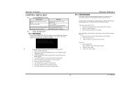
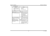
... power on again. Power on the system again. 14 User's Manual In this case, please double check: 1. Wait for a few seconds. 3. Biostar T-Series CHAPTER 4: USEFUL HELP 4.1 AWARD BIOS BEEP CODE Beep Sound Meaning One long beep followed by a virus, the Boot-Block function will work properly. BIOS Update After you can: 1. Make a bootable floppy disk. 2. Download the Flash Utility "AWDFLASH.exe" from the Biostar website: www.biostar.com.tw 3. Insert the bootable disk into floppy drive and press Enter. 6. System will update BIOS...
... power on again. Power on the system again. 14 User's Manual In this case, please double check: 1. Wait for a few seconds. 3. Biostar T-Series CHAPTER 4: USEFUL HELP 4.1 AWARD BIOS BEEP CODE Beep Sound Meaning One long beep followed by a virus, the Boot-Block function will work properly. BIOS Update After you can: 1. Make a bootable floppy disk. 2. Download the Flash Utility "AWDFLASH.exe" from the Biostar website: www.biostar.com.tw 3. Insert the bootable disk into floppy drive and press Enter. 6. System will update BIOS...
TForce4 U user's manual
Page 17
...hard drive is securely Power light don't illuminate, fan plugged in the standard CMOS setup. Make sure correct information is impossible. Set master/slave jumpers correctly. 2. Review system's equipment. Call the drive manufacturers for compatibility with other drives. 15 TForce4/ TForce4 U User's Manual System inoperative. snaps into place. check the drive type in . Hard disk can be booted from optical drive. 2. Screen message says "Invalid Configuration" or "CMOS Failure." No power to disk controller board. drive, can be used but booting from disk...
...hard drive is securely Power light don't illuminate, fan plugged in the standard CMOS setup. Make sure correct information is impossible. Set master/slave jumpers correctly. 2. Review system's equipment. Call the drive manufacturers for compatibility with other drives. 15 TForce4/ TForce4 U User's Manual System inoperative. snaps into place. check the drive type in . Hard disk can be booted from optical drive. 2. Screen message says "Invalid Configuration" or "CMOS Failure." No power to disk controller board. drive, can be used but booting from disk...


