
TForce4 U user's manual
Page 3
...One SPDIF-Out connector. Two PCI-Express X1 slots. Two Ultra DMA 133/100/66/33 IDE connectors. Biostar T-Series Chapter 1: Introduction 1.1 MOTHERBOARD FEATURES CPU Supports Socket 939. NVIDIA nForce4 Ultra for highest system and application performance. Environment Control initiatives, H/W Monitor ...support Windows 98SE and Windows ME. Supports PIO mode 0~4, Block Mode and Ultra DMA 33/66/100/133 bus master mode. 1 TForce4/ TForce4 U AC'97 Audio Sound Codec Chip: ALC850, supports 8 channels audio output. RAID 1 disk mirroring support for fault tolerance Support ...
...One SPDIF-Out connector. Two PCI-Express X1 slots. Two Ultra DMA 133/100/66/33 IDE connectors. Biostar T-Series Chapter 1: Introduction 1.1 MOTHERBOARD FEATURES CPU Supports Socket 939. NVIDIA nForce4 Ultra for highest system and application performance. Environment Control initiatives, H/W Monitor ...support Windows 98SE and Windows ME. Supports PIO mode 0~4, Block Mode and Ultra DMA 33/66/100/133 bus master mode. 1 TForce4/ TForce4 U AC'97 Audio Sound Codec Chip: ALC850, supports 8 channels audio output. RAID 1 disk mirroring support for fault tolerance Support ...
TForce4 U user's manual
Page 4
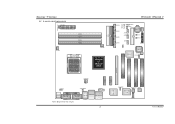
Biostar T-Series 1.2 LAYOUT AND COMPONENTS JATXPWR1 JDDR_0V>3V JCFAN1 DIMM3 DIMM1 DIMM4 DIMM2 Socket 939 JNBFAN1 nForce4 or nForce4 Ultra IDE2 IDE1 LED_D1 LED_D2 LED_DIMM LED_5SB FDD1 TForce4/ TForce4 U JSATA4 JSATA3 JSATA2 JSATA1 JCMOS1 JUSBV1 JUSB3 JUSB2 JUSB1 JCI1 JSFAN1 BAT1 RSTSW PWRSW JPANEL1 BIOS Super I/O JSFAN2 J1394A1 PCI-EX16 XGP1 JATXPWR2 JKBMSV1 J1394_USBV1 ...
Biostar T-Series 1.2 LAYOUT AND COMPONENTS JATXPWR1 JDDR_0V>3V JCFAN1 DIMM3 DIMM1 DIMM4 DIMM2 Socket 939 JNBFAN1 nForce4 or nForce4 Ultra IDE2 IDE1 LED_D1 LED_D2 LED_DIMM LED_5SB FDD1 TForce4/ TForce4 U JSATA4 JSATA3 JSATA2 JSATA1 JCMOS1 JUSBV1 JUSB3 JUSB2 JUSB1 JCI1 JSFAN1 BAT1 RSTSW PWRSW JPANEL1 BIOS Super I/O JSFAN2 J1394A1 PCI-EX16 XGP1 JATXPWR2 JKBMSV1 J1394_USBV1 ...
TForce4 U user's manual
Page 6
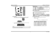
... at both sides of the slot outward at the same time, and pull the modules out vertically. DDR Installation Notice For AMD K8 939 CPU launched before Rev. E, please follow the table below to Table 1 for CPU Revision) "SS" represents Single Side DDR memory ...512MB/1GB *1 128MB/256MB/512MB/1GB *1 128MB/256MB/512MB/1GB *1 Total Memory Size Max is properly seated. Biostar T-Series 2.2 SYSTEM MEMORY DIMM3 DIMM1 DIMM4 DIMM2 Codec BIOS A. DDR Modules 1. TForce4/ TForce4 U B. C. Star sign "*" represents leave the DIMM socket empty. Know your DDR memory module, or the system...
... at both sides of the slot outward at the same time, and pull the modules out vertically. DDR Installation Notice For AMD K8 939 CPU launched before Rev. E, please follow the table below to Table 1 for CPU Revision) "SS" represents Single Side DDR memory ...512MB/1GB *1 128MB/256MB/512MB/1GB *1 128MB/256MB/512MB/1GB *1 Total Memory Size Max is properly seated. Biostar T-Series 2.2 SYSTEM MEMORY DIMM3 DIMM1 DIMM4 DIMM2 Codec BIOS A. DDR Modules 1. TForce4/ TForce4 U B. C. Star sign "*" represents leave the DIMM socket empty. Know your DDR memory module, or the system...
