

TForce 550 user's manual
Page 2
... Processing Unit (CPU 5 2.2 FAN Headers 6 2.3 Installing System Memory 8 2.4 Connectors and Slots 10 Chapter 3: Headers & Jumpers Setup 12 3.1 How to Setup Jumpers 12 3.2 Detail Settings 12 Chapter 4: NVIDIA RAID Functions 21 4.1 Operation System 21 4.2 Raid Arrays 21 4.3 How RAID Works 21 5.1: T-Power Introduction 24 5.2: T-Power BIOS Feature 25 5.3 T-Power Windows Feature 33 Chapter 6: Useful Help 42 6.1 Driver Installation Note 42 6.2 Award BIOS Beep Code 43 6.3 Extra Information 43 6.4 Troubleshooting 45 Appendencies: SPEC In Other...
... Processing Unit (CPU 5 2.2 FAN Headers 6 2.3 Installing System Memory 8 2.4 Connectors and Slots 10 Chapter 3: Headers & Jumpers Setup 12 3.1 How to Setup Jumpers 12 3.2 Detail Settings 12 Chapter 4: NVIDIA RAID Functions 21 4.1 Operation System 21 4.2 Raid Arrays 21 4.3 How RAID Works 21 5.1: T-Power Introduction 24 5.2: T-Power BIOS Feature 25 5.3 T-Power Windows Feature 33 Chapter 6: Useful Help 42 6.1 Driver Installation Note 42 6.2 Award BIOS Beep Code 43 6.3 Extra Information 43 6.4 Troubleshooting 45 Appendencies: SPEC In Other...
TForce 550 user's manual
Page 3
... lighting. „ Always disconnect the computer from dangerous area, such as heat source, humid air and water. 1.2 PACKAGE CHECKLIST FDD Cable X 1 HDD Cable X 1 Serial ATA Cable X 1 Serial ATA Power Cable X 1 Rear I/O Panel for choosing our product. Loose parts will cause short circuits which may damage the equipment. „ Keep the computer from power outlet before operation. „ Before you for ATX Case X 1 User's Manual X 1 Fully Setup Driver CD X 1 USB 2.0 Cable X1 (optional...
... lighting. „ Always disconnect the computer from dangerous area, such as heat source, humid air and water. 1.2 PACKAGE CHECKLIST FDD Cable X 1 HDD Cable X 1 Serial ATA Cable X 1 Serial ATA Power Cable X 1 Rear I/O Panel for choosing our product. Loose parts will cause short circuits which may damage the equipment. „ Keep the computer from power outlet before operation. „ Before you for ATX Case X 1 User's Manual X 1 Fully Setup Driver CD X 1 USB 2.0 Cable X1 (optional...
TForce 550 user's manual
Page 4
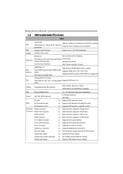
... header Chassis open header (optional) CMOS clear header 2 10 / 100 Mb/s and 1Gb/s Auto-Negotiation 8 channels audio out HD Audio x4 Supports PCI expansion cards x1 Supports PCI Express x16 expansion cards x2 Supports PCI Express x1 expansion cards x1 Each connector supports 2 Floppy drives x1 Each connector supports 1 Printer port x1 Each connector supports 2 IDE device x4 Each connector supports 1 SATA devices x1 Supports front panel facilities x1 Supports front panel audio function x1 Supports CD audio-in function x1 Supports digital audio out function x1 CPU Fan power supply (with Smart...
... header Chassis open header (optional) CMOS clear header 2 10 / 100 Mb/s and 1Gb/s Auto-Negotiation 8 channels audio out HD Audio x4 Supports PCI expansion cards x1 Supports PCI Express x16 expansion cards x2 Supports PCI Express x1 expansion cards x1 Each connector supports 2 Floppy drives x1 Each connector supports 1 Printer port x1 Each connector supports 2 IDE device x4 Each connector supports 1 SATA devices x1 Supports front panel facilities x1 Supports front panel audio function x1 Supports CD audio-in function x1 Supports digital audio out function x1 CPU Fan power supply (with Smart...
TForce 550 user's manual
Page 5
...) Power Connector (4pin) PS/2 Keyboard PS/2 Mouse Back Panel Serial Port I/O LAN port USB Port Audio Jack Board Size ATX Form Factor Special Features NVIDIA nTunes RAID 0 / 1 / 0+1support OS Support Windows 2K / XP TForce 550 SPEC x2 Each connector supports 2 front panel USB ports x1 Connects to Power supply x1 Connects to Power supply x1 Connects to PS/2 Keyboard x1 Connects to PS/2 Mouse x1 Provide RS-232 Serial connection x1 Connects to RJ-45 ethernet cable x6 Connects to USB devices x6 Provide Audio-In/Out and microphone connection 219 x 304 (mm) Biostar...
...) Power Connector (4pin) PS/2 Keyboard PS/2 Mouse Back Panel Serial Port I/O LAN port USB Port Audio Jack Board Size ATX Form Factor Special Features NVIDIA nTunes RAID 0 / 1 / 0+1support OS Support Windows 2K / XP TForce 550 SPEC x2 Each connector supports 2 front panel USB ports x1 Connects to Power supply x1 Connects to Power supply x1 Connects to PS/2 Keyboard x1 Connects to PS/2 Mouse x1 Provide RS-232 Serial connection x1 Connects to RJ-45 ethernet cable x6 Connects to USB devices x6 Provide Audio-In/Out and microphone connection 219 x 304 (mm) Biostar...

TForce 550 user's manual
Page 8
... 2 Smart Fan Control 3 FAN RPM rate sense 4 Smart Fan Control 6 The fan cable and connector may be different according to complete the installation. Step 5: Put the CPU Fan on the CPU and buckle it. Motherboard Manual Step 4: Hold the CPU down firmly, and then close the lever toward direct B to the fan manufacturer. Connect the fan cable to the connector while matching the black wire to the JCFAN1. This completes the installation. 2.2 FAN HEADERS These fan headers support cooling-fans...
... 2 Smart Fan Control 3 FAN RPM rate sense 4 Smart Fan Control 6 The fan cable and connector may be different according to complete the installation. Step 5: Put the CPU Fan on the CPU and buckle it. Motherboard Manual Step 4: Hold the CPU down firmly, and then close the lever toward direct B to the fan manufacturer. Connect the fan cable to the connector while matching the black wire to the JCFAN1. This completes the installation. 2.2 FAN HEADERS These fan headers support cooling-fans...
TForce 550 user's manual
Page 11
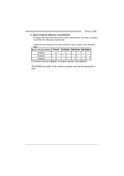
TForce 550 C. Duual Channel Status DDR2A1 DDR2B1 DDR2A2 DDR2B2 Enabled O O X X Enabled X X O O Enabled O O O O (O means memory installed, X means memory not installed.) The DRAM bus width of the same density in pairs, shown in the following requirements: Install memory module of the memory module must meet the following table. Dual Channel Memory installation To trigger the Dual Channel function of the motherboard, the memory module must be the same (x8 or x16) 9
TForce 550 C. Duual Channel Status DDR2A1 DDR2B1 DDR2A2 DDR2B2 Enabled O O X X Enabled X X O O Enabled O O O O (O means memory installed, X means memory not installed.) The DRAM bus width of the same density in pairs, shown in the following requirements: Install memory module of the memory module must meet the following table. Dual Channel Memory installation To trigger the Dual Channel function of the motherboard, the memory module must be the same (x8 or x16) 9

TForce 550 user's manual
Page 12
... Mode 0~4, Bus Master, and Ultra DMA 33/66/100/133 functionality. It has two HDD connectors IDE1 (primary) and IDE2 (secondary). The first hard drive should always be connected to four hard disk drives. IDE1 40 39 2 1 10 The IDE connectors can connect a master and a slave drive, so you can connect up to IDE1. This connector supports the provided floppy drive ribbon cables. 34 33 2 1 IDE1: Hard Disk Connectors The motherboard has a 32-bit Enhanced PCI IDE Controller...
... Mode 0~4, Bus Master, and Ultra DMA 33/66/100/133 functionality. It has two HDD connectors IDE1 (primary) and IDE2 (secondary). The first hard drive should always be connected to four hard disk drives. IDE1 40 39 2 1 10 The IDE connectors can connect a master and a slave drive, so you can connect up to IDE1. This connector supports the provided floppy drive ribbon cables. 34 33 2 1 IDE1: Hard Disk Connectors The motherboard has a 32-bit Enhanced PCI IDE Controller...
TForce 550 user's manual
Page 14
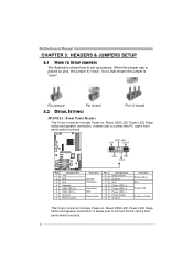
...9 Sleep control Speaker Connector 10 Ground 11 N/A 12 Power LED (+) Hard drive LED 13 Power LED (+) 14 Power LED (-) Reset button 15 Power button 16 Ground Function Sleep button N/A Power LED Power-on button This 16-pin connector includes Power-on pins, the jumper is "close", if not, that means the jumper is "open". It allows user to set up jumpers. It allows user to connect the PC case's front panel switch functions. 12 Pin opened Pin closed Pin1-2 closed 3.2 DETAIL SETTINGS JPANEL1: Front Panel Header This 16-pin connector includes Power-on, Reset, HDD LED, Power LED...
...9 Sleep control Speaker Connector 10 Ground 11 N/A 12 Power LED (+) Hard drive LED 13 Power LED (+) 14 Power LED (-) Reset button 15 Power button 16 Ground Function Sleep button N/A Power LED Power-on button This 16-pin connector includes Power-on pins, the jumper is "close", if not, that means the jumper is "open". It allows user to set up jumpers. It allows user to connect the PC case's front panel switch functions. 12 Pin opened Pin closed Pin1-2 closed 3.2 DETAIL SETTINGS JPANEL1: Front Panel Header This 16-pin connector includes Power-on, Reset, HDD LED, Power LED...
TForce 550 user's manual
Page 16
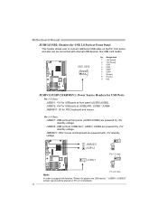
... powered by +5V standby voltage. JUSBV2: USB ports at JUSBLAN1, JUSB3 / JUSB4 are powered by +5V standby voltage. JUSBV2: +5V for USB ports at front panel (JUSB1/JUSB2). Motherboard Manual JUSB1/JUSB2: Headers for USB 2.0 Ports at Front Panel This header allows user to support this function "Power-On system via USB device," "JUSBV1/ JUSBV2" jumper cap should be placed on the PC front panel, and also can be connected with internal USB devices, like USB card reader. 2 10 1 9 Pin...
... powered by +5V standby voltage. JUSBV2: USB ports at JUSBLAN1, JUSB3 / JUSB4 are powered by +5V standby voltage. JUSBV2: +5V for USB ports at front panel (JUSB1/JUSB2). Motherboard Manual JUSB1/JUSB2: Headers for USB 2.0 Ports at Front Panel This header allows user to support this function "Power-On system via USB device," "JUSBV1/ JUSBV2" jumper cap should be placed on the PC front panel, and also can be connected with internal USB devices, like USB card reader. 2 10 1 9 Pin...
TForce 550 user's manual
Page 17
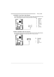
... Right in 4 GPIO 5 Right line in 6 Jack Sense 7 Front Sense 8 Key 9 Left line in 10 Jack Sense JCDIN1: CD-ROM Audio-in Connector This connector allows user to connect the front audio output cable with the PC front panel. TForce 550 JAUDIOF1: Front Panel Audio Header This header allows user to connect the audio source from the variaty devices, like CD-ROM, DVD-ROM, PCI sound card, PCI TV turner card etc. 1 4 Pin Assignment 1 Left Channel Input 2 Ground 3 Ground 4 Right...
... Right in 4 GPIO 5 Right line in 6 Jack Sense 7 Front Sense 8 Key 9 Left line in 10 Jack Sense JCDIN1: CD-ROM Audio-in Connector This connector allows user to connect the front audio output cable with the PC front panel. TForce 550 JAUDIOF1: Front Panel Audio Header This header allows user to connect the audio source from the variaty devices, like CD-ROM, DVD-ROM, PCI sound card, PCI TV turner card etc. 1 4 Pin Assignment 1 Left Channel Input 2 Ground 3 Ground 4 Right...
TForce 550 user's manual
Page 18
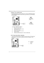
... user to restore the BIOS safe setting and the CMOS data, please carefully follow the procedures to avoid damaging the motherboard. 13 Pin 1-2 Close: Normal Operation (default). 1 3 13 Pin 2-3 Close: Clear CMOS data. ※ Clear CMOS Procedures: 1. JCI1: Chassis Open Header (optional) This connector allows system to monitor PC case open signal 2 Ground 16 Set the jumper to "Pin 1-2 close ". 3. Power on next boot-up. 12 Pin Assignment 1 Case open status. Wait for five seconds. 4. Motherboard Manual JCMOS1: Clear CMOS Header...
... user to restore the BIOS safe setting and the CMOS data, please carefully follow the procedures to avoid damaging the motherboard. 13 Pin 1-2 Close: Normal Operation (default). 1 3 13 Pin 2-3 Close: Clear CMOS data. ※ Clear CMOS Procedures: 1. JCI1: Chassis Open Header (optional) This connector allows system to monitor PC case open signal 2 Ground 16 Set the jumper to "Pin 1-2 close ". 3. Power on next boot-up. 12 Pin Assignment 1 Case open status. Wait for five seconds. 4. Motherboard Manual JCMOS1: Clear CMOS Header...
TForce 550 user's manual
Page 19
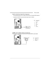
JSPDIF_OUT 13 Pin Assignment 1 +5V 2 SPDIF_OUT 3 Ground 17 TForce 550 JSATA1~JSATA4: Serial ATA Connectors The motherboard has a PCI to SATA Controller with 2 channels SATA interface, it satisfies the SATA 2.0 spec and with transfer rate of 3.0Gb/s. 14 7 Pin Assignment 1 Ground 2 TX+ 3 TX4 Ground 5 RX6 RX+ 7 Ground JSPDIF_OUT: Digital Audio out Connectors This connector allows user to connect the PCI bracket SPDIF output header.
JSPDIF_OUT 13 Pin Assignment 1 +5V 2 SPDIF_OUT 3 Ground 17 TForce 550 JSATA1~JSATA4: Serial ATA Connectors The motherboard has a PCI to SATA Controller with 2 channels SATA interface, it satisfies the SATA 2.0 spec and with transfer rate of 3.0Gb/s. 14 7 Pin Assignment 1 Ground 2 TX+ 3 TX4 Ground 5 RX6 RX+ 7 Ground JSPDIF_OUT: Digital Audio out Connectors This connector allows user to connect the PCI bracket SPDIF output header.
TForce 550 user's manual
Page 21
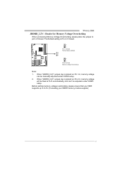
... setting memory voltage overclocking, please ensure that your DDR supports up to pin1-2 Closed. The Default setting is placed on Pin 2-3, memory voltage will be fixed at 2.2V automatically, and can be adjusted under CMOS setup. 2. When "JDDRII_2.2V" jumper cap is placed on Pin 1-2, memory voltage can 't be manually adjusted under COMS setup. When "JDDRII_2.2V" jumper cap is Pin 2-3 Closed. 3 1 Pin 1-2 Close: Normal status (default). 3 1 3 1 Pin 2-3 Close: Memory voltage Overclocking. TForce 550 JDDRII_2.2V : Header for Memory Voltage Overclocking When...
... setting memory voltage overclocking, please ensure that your DDR supports up to pin1-2 Closed. The Default setting is placed on Pin 2-3, memory voltage will be fixed at 2.2V automatically, and can be adjusted under CMOS setup. 2. When "JDDRII_2.2V" jumper cap is placed on Pin 1-2, memory voltage can 't be manually adjusted under COMS setup. When "JDDRII_2.2V" jumper cap is Pin 2-3 Closed. 3 1 Pin 1-2 Close: Normal status (default). 3 1 3 1 Pin 2-3 Close: Memory voltage Overclocking. TForce 550 JDDRII_2.2V : Header for Memory Voltage Overclocking When...
TForce 550 user's manual
Page 23
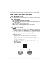
... large files. Depending on the system environment. No capacity loss penalty for many applications. Features and Benefits Drives: Minimum 1, and maximum is lost. Fault Tolerance: No. TForce 550 CHAPTER 4: NVIDIA RAID FUNCTIONS 4.1 OPERATION SYSTEM z Supports Windows XP Home/Professional Edition, and Windows 2000 Professional. 4.2 RAID ARRAYS NVRAID supports the following types of the RAID set during the creation of RAID arrays: RAID 0: RAID 0 defines a disk...
... large files. Depending on the system environment. No capacity loss penalty for many applications. Features and Benefits Drives: Minimum 1, and maximum is lost. Fault Tolerance: No. TForce 550 CHAPTER 4: NVIDIA RAID FUNCTIONS 4.1 OPERATION SYSTEM z Supports Windows XP Home/Professional Edition, and Windows 2000 Professional. 4.2 RAID ARRAYS NVRAID supports the following types of the RAID set during the creation of RAID arrays: RAID 0: RAID 0 defines a disk...
TForce 550 user's manual
Page 28
..., sometimes downgrading the memory frequency is necessary when CPU frequency is increased. Choices: DDR2 400, DDR2 533, DDR2 667, DDR2 800 (MHz). PCI-Express Overclock Setting: PCIE Clock: It helps to 450, with an interval of 1MHz. Choices: x1, x2, x3, x4, x5, Auto. 26 Choices: This range is from 100 to system performance. CPU Frequency: CPU Frequency is from 200 to increase VGA card performance. Choices...
..., sometimes downgrading the memory frequency is necessary when CPU frequency is increased. Choices: DDR2 400, DDR2 533, DDR2 667, DDR2 800 (MHz). PCI-Express Overclock Setting: PCIE Clock: It helps to 450, with an interval of 1MHz. Choices: x1, x2, x3, x4, x5, Auto. 26 Choices: This range is from 100 to system performance. CPU Frequency: CPU Frequency is from 200 to increase VGA card performance. Choices...
TForce 550 user's manual
Page 31
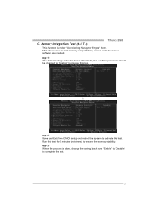
.... 29 Memory Integration Test (M.I.T.): This function is "Disabled"; the condition parameter should be changed to "Enable" to proceed this test for 5 minutes (minimum) to activate this item is under this test. Run this test. ↓ Step 2: Save and Exit from "Enable" to "Disable" to test memory compatibilities, and no extra devices or software are needed. TForce 550 C. Step 1: The default setting under "Overclocking Navigator Engine...
.... 29 Memory Integration Test (M.I.T.): This function is "Disabled"; the condition parameter should be changed to "Enable" to proceed this test for 5 minutes (minimum) to activate this item is under this test. Run this test. ↓ Step 2: Save and Exit from "Enable" to "Disable" to test memory compatibilities, and no extra devices or software are needed. TForce 550 C. Step 1: The default setting under "Overclocking Navigator Engine...
TForce 550 user's manual
Page 32
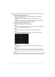
... choose the BIOS file downloaded in the default BIOS setting, and all overclock settings will be seen under T-Power BIOS setup; Step 2: Insert the floppy disk and reboot the system to get into a floppy disk. Step 5: When the BIOS update is a safe and quick way to finish the process. Step 4: Press "Enter" key to start BIOS file loading, and BIOS updating will reboot automatically to upgrade BIOS. Self Recovery System (S.R.S.): This function can update the system BIOS by simply pressing "Enter" key for...
... choose the BIOS file downloaded in the default BIOS setting, and all overclock settings will be seen under T-Power BIOS setup; Step 2: Insert the floppy disk and reboot the system to get into a floppy disk. Step 5: When the BIOS update is a safe and quick way to finish the process. Step 4: Press "Enter" key to start BIOS file loading, and BIOS updating will reboot automatically to upgrade BIOS. Self Recovery System (S.R.S.): This function can update the system BIOS by simply pressing "Enter" key for...
TForce 550 user's manual
Page 33
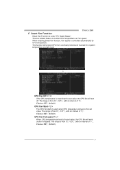
...; (default). Fan speed. This function will turn off. Choices: 16℃ (default). When enabling Smart Fan function, Fan speed is a brilliant feature to control CPU Temperature vs. The range is lower than the set value. The range is under Full Speed. Choices: 52℃ (default). 31 Smart Fan Function: Smart Fan Function is from 0℃~127℃, with an interval of 1℃. CPU Fan Start The CPU fan starts to this set value, the CPU fan will protect CPU from...
...; (default). Fan speed. This function will turn off. Choices: 16℃ (default). When enabling Smart Fan function, Fan speed is a brilliant feature to control CPU Temperature vs. The range is lower than the set value. The range is under Full Speed. Choices: 52℃ (default). 31 Smart Fan Function: Smart Fan Function is from 0℃~127℃, with an interval of 1℃. CPU Fan Start The CPU fan starts to this set value, the CPU fan will protect CPU from...
TForce 550 user's manual
Page 45
... two short Video card not found during POST Long beeps every other second No DRAM detected or install 6.3 EXTRA INFORMATION A. Copy "AWDFLASH.exe" and respectively BIOS into floppy drive and press Enter. 6. Download the Flash Utility "AWDFLASH.exe" from Biostar website. 4. System will boot-up to restore BIOS. In this Case, please follow the procedure below to update BIOS or BIOS is shown after boot-up No error found or video card beeps memory bad High-low siren sound CPU overheated...
... two short Video card not found during POST Long beeps every other second No DRAM detected or install 6.3 EXTRA INFORMATION A. Copy "AWDFLASH.exe" and respectively BIOS into floppy drive and press Enter. 6. Download the Flash Utility "AWDFLASH.exe" from Biostar website. 4. System will boot-up to restore BIOS. In this Case, please follow the procedure below to update BIOS or BIOS is shown after boot-up No error found or video card beeps memory bad High-low siren sound CPU overheated...
TForce 550 user's manual
Page 47
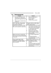
... files. Screen message says "Invalid Configuration" or "CMOS Failure." Make sure correct information is Power light don't illuminate, fan securely plugged in setup. inside power supply does not turn on . 3. Replace cable. System inoperative. Call the drive manufacturers for compatibility with other drives. 45 on . Using even pressure on , power indicator lights are lit, and hard drive is spinning. TForce 550 6.4 TROUBLESHOOTING Probable Solution 1. No power to disk controller board. Make sure power cable is in . Contact technical support. 2. Keyboard lights...
... files. Screen message says "Invalid Configuration" or "CMOS Failure." Make sure correct information is Power light don't illuminate, fan securely plugged in setup. inside power supply does not turn on . 3. Replace cable. System inoperative. Call the drive manufacturers for compatibility with other drives. 45 on . Using even pressure on , power indicator lights are lit, and hard drive is spinning. TForce 550 6.4 TROUBLESHOOTING Probable Solution 1. No power to disk controller board. Make sure power cable is in . Contact technical support. 2. Keyboard lights...


