Bios Setup
Page 2
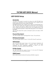
... Support AMI ACPI UEFI BIOS support Version 1.0/2.0 of this manual is supported. 1 TA75M UEFI BIOS Manual UEFI BIOS Setup Introduction The purpose of Advanced Configuration and Power interface specification (ACPI). The Setup program allows users to modify the basic system configuration... and save these settings to guide you through the options and settings in the AMI UEFI BIOS Setup program on this manual will to NVRAM. BIOS activates at the first stage of this motherboard...
... Support AMI ACPI UEFI BIOS support Version 1.0/2.0 of this manual is supported. 1 TA75M UEFI BIOS Manual UEFI BIOS Setup Introduction The purpose of Advanced Configuration and Power interface specification (ACPI). The Setup program allows users to modify the basic system configuration... and save these settings to guide you through the options and settings in the AMI UEFI BIOS Setup program on this manual will to NVRAM. BIOS activates at the first stage of this motherboard...
Bios Setup
Page 3
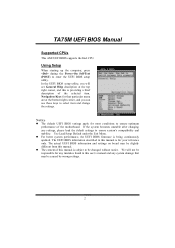
...you will not be caused by wrong-settings. 2 Using Setup When starting up the computer, press during the Power-On Self-Test (POST) to ensure optimum performance of the motherboard. The actual UEFI BIOS information and settings on board may be responsible for most conditions to enter the UEFI ... better system performance, the UEFI BIOS firmware is providing a brief description of this is being continuously updated. Navigation Keys for your reference only. TA75M UEFI BIOS Manual Supported CPUs This AMI UEFI BIOS supports the Intel CPU. Use Load Setup Default under the Exit Menu.
...you will not be caused by wrong-settings. 2 Using Setup When starting up the computer, press during the Power-On Self-Test (POST) to ensure optimum performance of the motherboard. The actual UEFI BIOS information and settings on board may be responsible for most conditions to enter the UEFI ... better system performance, the UEFI BIOS firmware is providing a brief description of this is being continuously updated. Navigation Keys for your reference only. TA75M UEFI BIOS Manual Supported CPUs This AMI UEFI BIOS supports the Intel CPU. Use Load Setup Default under the Exit Menu.

Setup Manual
Page 3
Before you start installing the motherboard, please make sure you follow the instructions below: „ Prepare a dry and stable working environment with sufficient lighting. „ Always disconnect the computer from power outlet before operation. „ Before you for ATX Case X1 User's Manual ...45 degrees Celsius. 1.2 PACKAGE CHECKLIST Serial ATA Cable X4 Rear I/O Panel for choosing our product. CHAPTER 1: INTRODUCTION TA75M 1.1 BEFORE YOU START Thank you take the motherboard out from dangerous area, such as heat source, humid air and water. „ The operating temperatures of the ...
Before you start installing the motherboard, please make sure you follow the instructions below: „ Prepare a dry and stable working environment with sufficient lighting. „ Always disconnect the computer from power outlet before operation. „ Before you for ATX Case X1 User's Manual ...45 degrees Celsius. 1.2 PACKAGE CHECKLIST Serial ATA Cable X4 Rear I/O Panel for choosing our product. CHAPTER 1: INTRODUCTION TA75M 1.1 BEFORE YOU START Thank you take the motherboard out from dangerous area, such as heat source, humid air and water. „ The operating temperatures of the ...
Setup Manual
Page 4
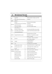
SATA III Integrated Serial ATA Controller SATA Version 3.0 specification compliant. Motherboard Manual 1.3 MOTHERBOARD FEATURES SPEC Socket FM1 AMD 64 Architecture enables 32 and 64 bit CPU AMD A-Series / E2-Series processors computing Chipset AMD A75 ITE 8728 Provides ... panel audio function S/PDIF out Connector x1 Supports digital audio out function Consumer IR Connector x1 Supports infrared function CPU Fan Header x1 CPU Fan power supply (with Smart Fan function) System Fan Header x2 System Fan...
SATA III Integrated Serial ATA Controller SATA Version 3.0 specification compliant. Motherboard Manual 1.3 MOTHERBOARD FEATURES SPEC Socket FM1 AMD 64 Architecture enables 32 and 64 bit CPU AMD A-Series / E2-Series processors computing Chipset AMD A75 ITE 8728 Provides ... panel audio function S/PDIF out Connector x1 Supports digital audio out function Consumer IR Connector x1 Supports infrared function CPU Fan Header x1 CPU Fan power supply (with Smart Fan function) System Fan Header x2 System Fan...
Setup Manual
Page 8
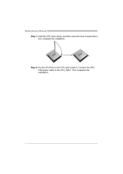
Step 4: Put the CPU Fan on the CPU and buckle it. Connect the CPU FAN power cable to complete the installation. Motherboard Manual Step 3: Hold the CPU down firmly, and then close the lever toward direct B to the CPU_FAN1. This completes the installation. 6
Step 4: Put the CPU Fan on the CPU and buckle it. Connect the CPU FAN power cable to complete the installation. Motherboard Manual Step 3: Hold the CPU down firmly, and then close the lever toward direct B to the CPU_FAN1. This completes the installation. 6
Setup Manual
Page 12
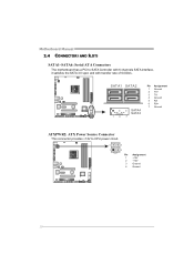
Motherboard Manual 2.4 CONNECTORS AND SLOTS SATA1~SATA6: Serial ATA Connectors The motherboard has a PCI to CPU power circuit. 4 3 1 2 Pin Assignment 1 +12V 2 +12V 3 Ground 4 Ground 10 SATA1 SATA2 S ATA4 S ATA3 14 7 Pin Assignment 1 Ground 2 TX+ 3 TX4 Ground 5 RX6 RX+ 7 Ground ATXPWR2: ATX Power Source Connector This connector provides +12V to SATA Controller with 6 channels SATA interface, it satisfies the SATA 3.0 spec and with transfer rate of 6.0Gb/s.
Motherboard Manual 2.4 CONNECTORS AND SLOTS SATA1~SATA6: Serial ATA Connectors The motherboard has a PCI to CPU power circuit. 4 3 1 2 Pin Assignment 1 +12V 2 +12V 3 Ground 4 Ground 10 SATA1 SATA2 S ATA4 S ATA3 14 7 Pin Assignment 1 Ground 2 TX+ 3 TX4 Ground 5 RX6 RX+ 7 Ground ATXPWR2: ATX Power Source Connector This connector provides +12V to SATA Controller with 6 channels SATA interface, it satisfies the SATA 3.0 spec and with transfer rate of 6.0Gb/s.

Setup Manual
Page 13
TA75M ATXPWR1: ATX Power Source Connector This connector allows user to connect 24-pin power connector on the ATX power supply. 12 24 1 13 Pin 13 14 15 16 17 18 19 20 21 ...3 Ground 4 +5V 5 Ground 6 +5V 7 Ground 8 PW_OK 9 Standby Voltage+5V 10 +12V 11 +12V 12 +3.3V Before you power on the system, please make sure that both ATXPWR1 and ATXPWR2 connectors have been plugged-in. PCI1 11 This PCI slot is a bus standard for...as 32 bits. PCI stands for expansion cards. PCI1: Peripheral Component Interconnect Slot This motherboard is equipped with 1 standard PCI slot.
TA75M ATXPWR1: ATX Power Source Connector This connector allows user to connect 24-pin power connector on the ATX power supply. 12 24 1 13 Pin 13 14 15 16 17 18 19 20 21 ...3 Ground 4 +5V 5 Ground 6 +5V 7 Ground 8 PW_OK 9 Standby Voltage+5V 10 +12V 11 +12V 12 +3.3V Before you power on the system, please make sure that both ATXPWR1 and ATXPWR2 connectors have been plugged-in. PCI1 11 This PCI slot is a bus standard for...as 32 bits. PCI stands for expansion cards. PCI1: Peripheral Component Interconnect Slot This motherboard is equipped with 1 standard PCI slot.
Setup Manual
Page 16
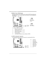
... for five seconds. 4. Set the jumper to "Pin 1-2 close ". 3. Set the jumper to "Pin 2-3 close ". 5. Please carefully follow the procedures to avoid damaging the motherboard. 31 Pin 1-2 Close: Normal Operation (default). 31 31 Pin 2-3 Close: Clear CMOS data. ※ Clear CMOS Procedures: 1. Load Optimal Defaults and save settings in CMOS... 3 Transmitted data 4 Data terminal ready 5 Signal ground 6 Data set ready 7 Request to send 8 Clear to restore the BIOS safe setting and the CMOS data. Power on pin2-3 allows user to send 9 Ring indicator 10 NC 14 Remove AC...
... for five seconds. 4. Set the jumper to "Pin 1-2 close ". 3. Set the jumper to "Pin 2-3 close ". 5. Please carefully follow the procedures to avoid damaging the motherboard. 31 Pin 1-2 Close: Normal Operation (default). 31 31 Pin 2-3 Close: Clear CMOS data. ※ Clear CMOS Procedures: 1. Load Optimal Defaults and save settings in CMOS... 3 Transmitted data 4 Data terminal ready 5 Signal ground 6 Data set ready 7 Request to send 8 Clear to restore the BIOS safe setting and the CMOS data. Power on pin2-3 allows user to send 9 Ring indicator 10 NC 14 Remove AC...

Setup Manual
Page 18
...+ 10 ID 1 20 Pin 11 12 13 14 15 16 17 18 19 20 10 11 Assignment D2+ D2Ground SSTX2+ SSTX2Ground SSRX2+ SSRX2VBUS1 Key 16 Motherboard Manual CIR1: Consumer IR Connector This header is for infrared remote control and communication. 26 15 Pin Assignment 1 IrDA serial input 2 Ground 3 Ground 4... Key 5 IrDA serial output 6 IR Power JFRONT_USB3_1: Header for USB 3.0 Ports at Front Panel This header allows user to connect additional USB cable on the PC front panel, and also can...
...+ 10 ID 1 20 Pin 11 12 13 14 15 16 17 18 19 20 10 11 Assignment D2+ D2Ground SSTX2+ SSTX2Ground SSRX2+ SSRX2VBUS1 Key 16 Motherboard Manual CIR1: Consumer IR Connector This header is for infrared remote control and communication. 26 15 Pin Assignment 1 IrDA serial input 2 Ground 3 Ground 4... Key 5 IrDA serial output 6 IR Power JFRONT_USB3_1: Header for USB 3.0 Ports at Front Panel This header allows user to connect additional USB cable on the PC front panel, and also can...

Setup Manual
Page 20
SW_PWR1: Power Switch button. 18 PH1_D1~PH3_D3 NB_PH1_D1 ON OFF Phase Indicator Phase Active Phase Disable On-Board Buttons There are 6 LED indicators showing system status. Motherboard Manual On-Board LED Indicators There are 2 on-board buttons. NB_PH 1_D 1 PH 1_D 1 PH 2_D 2 PH 3_D 3 ...LED_D1 LED_D 2 LED_D1 & LED_D2: Debug Indicators PH1_D1 ~ PH3_D3 / NB_PH1_D1: Power Status Indicators Please refer to the tables below...
SW_PWR1: Power Switch button. 18 PH1_D1~PH3_D3 NB_PH1_D1 ON OFF Phase Indicator Phase Active Phase Disable On-Board Buttons There are 6 LED indicators showing system status. Motherboard Manual On-Board LED Indicators There are 2 on-board buttons. NB_PH 1_D 1 PH 1_D 1 PH 2_D 2 PH 3_D 3 ...LED_D1 LED_D 2 LED_D1 & LED_D2: Debug Indicators PH1_D1 ~ PH3_D3 / NB_PH1_D1: Power Status Indicators Please refer to the tables below...
Setup Manual
Page 32
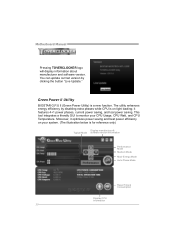
... while CPU is on your CPU Usage, CPU Watt, and CPU Temperature. it optimizes power saving and best power efficiency on light loading; Motherboard Manual Pressing TOVERCLOCKER logo will display information about manufacturer and software version. The utility enhances ...energy efficiency by clicking the button "Live Update." Green Power II Utility BIOSTAR G.P.U II (Green Power Utility) is for reference only...
... while CPU is on your CPU Usage, CPU Watt, and CPU Temperature. it optimizes power saving and best power efficiency on light loading; Motherboard Manual Pressing TOVERCLOCKER logo will display information about manufacturer and software version. The utility enhances ...energy efficiency by clicking the button "Live Update." Green Power II Utility BIOSTAR G.P.U II (Green Power Utility) is for reference only...
Setup Manual
Page 34
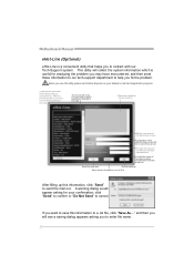
.... Exit this information, click "Send" to enter file name. 32 click "Send" to confirm or "Do Not Send" to . *Provid e the name of the power supply manufacturer and the model no. This utility will see a saving dialog appears asking you want to save this utility,please set Outlook Express as... Send th e mail ou t. A warning dialog would like to send t he copy to cancel. Provid e the name of the memory module ma nufa ct u rer. Motherboard Manual eHot-Line (Optional) eHot-Line is useful for your area or the are a close to yo u. Provid e the e-ma il address that you would...
.... Exit this information, click "Send" to enter file name. 32 click "Send" to confirm or "Do Not Send" to . *Provid e the name of the power supply manufacturer and the model no. This utility will see a saving dialog appears asking you want to save this utility,please set Outlook Express as... Send th e mail ou t. A warning dialog would like to send t he copy to cancel. Provid e the name of the memory module ma nufa ct u rer. Motherboard Manual eHot-Line (Optional) eHot-Line is useful for your area or the are a close to yo u. Provid e the e-ma il address that you would...
Setup Manual
Page 40
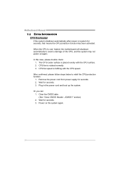
... INFORMATION CPU Overheated If the system shutdown automatically after power on the system again. 38 CPU fan is over heated, the motherboard will shutdown automatically to relief the CPU protection function. 1. CPU fan speed is placed evenly with the CPU speed. After confirmed, please follow... steps below to avoid a damage of the CPU, and the system may not power on again. Plug in the power cord and boot ...
... INFORMATION CPU Overheated If the system shutdown automatically after power on the system again. 38 CPU fan is over heated, the motherboard will shutdown automatically to relief the CPU protection function. 1. CPU fan speed is placed evenly with the CPU speed. After confirmed, please follow... steps below to avoid a damage of the CPU, and the system may not power on again. Plug in the power cord and boot ...

Setup Manual
Page 42
... cable running . System cannot boot after user installs a 1. Run SETUP program and select correct drive types. Indicator light on , power indicator lights are on keyboard does not shine. All hard disks are capable of breaking down firmly until the and hard drives are... securely plugged in; drive. Back up the hard drive is inoperative. Motherboard Manual 7.4 TROUBLESHOOTING Probable Solution 1. Make sure power cable is in the standard CMOS setup. 2. Replace cable. module snaps into place. fails to disk controller ...
... cable running . System cannot boot after user installs a 1. Run SETUP program and select correct drive types. Indicator light on , power indicator lights are on keyboard does not shine. All hard disks are capable of breaking down firmly until the and hard drives are... securely plugged in; drive. Back up the hard drive is inoperative. Motherboard Manual 7.4 TROUBLESHOOTING Probable Solution 1. Make sure power cable is in the standard CMOS setup. 2. Replace cable. module snaps into place. fails to disk controller ...


