
Setup Manual
Page 3
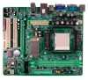
... wate r. 1.2 PACKAGE CHECKLIST FDD Cable X 1 HDD Cable X 1 Use r's Manual X 1 Fully Se tup Drive r C D X 1 Rear I/O Panel for choosing our product. NF61V Micro A M2 SE/NF61S Micro A M2 SE CHAPTER 1: INTRODUCTION 1.1 BEFORE YOU START Thank you take the mothe rboard out from anti-static bag, ground yourse lf prope rly by touching any unfastene d small parts inside the case afte r installation. Be fore you start installing the mo the rboa rd...
... wate r. 1.2 PACKAGE CHECKLIST FDD Cable X 1 HDD Cable X 1 Use r's Manual X 1 Fully Se tup Drive r C D X 1 Rear I/O Panel for choosing our product. NF61V Micro A M2 SE/NF61S Micro A M2 SE CHAPTER 1: INTRODUCTION 1.1 BEFORE YOU START Thank you take the mothe rboard out from anti-static bag, ground yourse lf prope rly by touching any unfastene d small parts inside the case afte r installation. Be fore you start installing the mo the rboa rd...
Setup Manual
Page 4
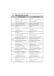
... / ALC888(Ver 5.x) ALC861VD(Ver 6.x) / ALC888(Ver 5.x) Sound 5.1 channels audio out (Ver 6.x) 7.1 channels audio out (Ver 5.x) 5.1 channels audio out (Ver 6.x) 7.1 channels audio out (Ver 5.x) Intel High-Definition Audio support Intel High-Definition Audio support Slots PCI slot x2 PCI slot x2 PCI Express x16 slot (x1 Speed) x1 PCI Express x 16 slot (x8 Speed) x1 PCI Express x 1 slot x1 PCI Express x 1 slot x1 2 Motherboard Manual 1.3 MOT HERBOARD FEAT URES NF61VMicro AM2 SE NF61S Micro AM2 SE Socket AM2 Socket AM2 CPU AMDSempron / Athlon 64 / Athlon 64 FX / Althlon...
... / ALC888(Ver 5.x) ALC861VD(Ver 6.x) / ALC888(Ver 5.x) Sound 5.1 channels audio out (Ver 6.x) 7.1 channels audio out (Ver 5.x) 5.1 channels audio out (Ver 6.x) 7.1 channels audio out (Ver 5.x) Intel High-Definition Audio support Intel High-Definition Audio support Slots PCI slot x2 PCI slot x2 PCI Express x16 slot (x1 Speed) x1 PCI Express x 16 slot (x8 Speed) x1 PCI Express x 1 slot x1 PCI Express x 1 slot x1 2 Motherboard Manual 1.3 MOT HERBOARD FEAT URES NF61VMicro AM2 SE NF61S Micro AM2 SE Socket AM2 Socket AM2 CPU AMDSempron / Athlon 64 / Athlon 64 FX / Althlon...
Setup Manual
Page 5
... inconnector(Optional) x1 CPU Fan header x1 System Fan header x1 CMOS clear header x1 USB connector x2 Printer Port Connector x1 Chassis open header(Optional) x1 Power Connector (24pin) x1 Power Connector (4pin) x1 PS/2 Keyboard x1 PS/2 Mouse x1 Serial Port x1 Back Panel VGA port x1 I/O LAN port x1 USB Port x4 Audio Jack (Ver 6.x) x3 Audio Jack (Ver 5.x) x6 BoardSize 207 x 244 (mm) Micro ATX Size Board Special NVIDIA nTunes Features RAID 0 / 1 support Windows 2000 / XP / VISTA OS Support Biostar Reserves the right to add or remove support for...
... inconnector(Optional) x1 CPU Fan header x1 System Fan header x1 CMOS clear header x1 USB connector x2 Printer Port Connector x1 Chassis open header(Optional) x1 Power Connector (24pin) x1 Power Connector (4pin) x1 PS/2 Keyboard x1 PS/2 Mouse x1 Serial Port x1 Back Panel VGA port x1 I/O LAN port x1 USB Port x4 Audio Jack (Ver 6.x) x3 Audio Jack (Ver 5.x) x6 BoardSize 207 x 244 (mm) Micro ATX Size Board Special NVIDIA nTunes Features RAID 0 / 1 support Windows 2000 / XP / VISTA OS Support Biostar Reserves the right to add or remove support for...
Setup Manual
Page 16
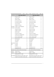
...INGS Pin1-2 closed JPANEL1: Front Panel Heade r This 16-pin connector includes Power-on button 14 It allows user to set up jumpers. SPK RST HL ED Pin Assignment 1 +5V 2 N/A 3 N/A 4 Speaker 5 HDD LED (+) 6 HDD LED (-) 7 Ground 8 Reset control Functio n Pin 9 Speaker 10 Connec tor 11 12 Hard drive 13 LED 14 Reset button 15 16 Assignment Sleep control Ground N/A Power LED (+) Power LED (+) Power LED (-) Power button Ground Functio n Sleep button N/A Power LED Power-on , Reset, HDD LED, Power LED, Sleep button and speaker connection. PWR_LED SLP On/ Off 9 + +- 16...
...INGS Pin1-2 closed JPANEL1: Front Panel Heade r This 16-pin connector includes Power-on button 14 It allows user to set up jumpers. SPK RST HL ED Pin Assignment 1 +5V 2 N/A 3 N/A 4 Speaker 5 HDD LED (+) 6 HDD LED (-) 7 Ground 8 Reset control Functio n Pin 9 Speaker 10 Connec tor 11 12 Hard drive 13 LED 14 Reset button 15 16 Assignment Sleep control Ground N/A Power LED (+) Power LED (+) Power LED (-) Power button Ground Functio n Sleep button N/A Power LED Power-on , Reset, HDD LED, Power LED, Sleep button and speaker connection. PWR_LED SLP On/ Off 9 + +- 16...

Setup Manual
Page 27
... floppy disk. 2. Download the Flash Utility "AWDFLASH.exe" from Biostar website. 4. Copy "AWDFLASH.exe" and respectively BIOS into floppy drive and press Enter. 6. In this Case, please follow the procedure below to restore BIOS. If the following message is invaded by two short beeps Meaning Video card not found or v ideo card memory bad High-low siren sound CPU overheated System will shut down automatically One Short beep when system boot-up No error found...
... floppy disk. 2. Download the Flash Utility "AWDFLASH.exe" from Biostar website. 4. Copy "AWDFLASH.exe" and respectively BIOS into floppy drive and press Enter. 6. In this Case, please follow the procedure below to restore BIOS. If the following message is invaded by two short beeps Meaning Video card not found or v ideo card memory bad High-low siren sound CPU overheated System will shut down automatically One Short beep when system boot-up No error found...
Setup Manual
Page 57
... settings to CMOS RAM. It provides ASL code for power management and device configuration capabilities as keyboard, mouse, serial ports and disk drives. This system controls most of the input and output devices such as defined in the Award™ BIOS Setup program on this motherboard. EPA Green PC Support T his AWARD BIOS supports Version 1.03 of the Advanced Power Management (APM) speci fi cation. ACPI Support Award ACPI BIOS support Version 1.0 of the booting process, loading and executing the operating system. NF61V Micro AM2 SE / NF61S Micro AM2 SE BIOS Setup BIOS Setup...
... settings to CMOS RAM. It provides ASL code for power management and device configuration capabilities as keyboard, mouse, serial ports and disk drives. This system controls most of the input and output devices such as defined in the Award™ BIOS Setup program on this motherboard. EPA Green PC Support T his AWARD BIOS supports Version 1.03 of the Advanced Power Management (APM) speci fi cation. ACPI Support Award ACPI BIOS support Version 1.0 of the booting process, loading and executing the operating system. NF61V Micro AM2 SE / NF61S Micro AM2 SE BIOS Setup BIOS Setup...
Setup Manual
Page 58
... navigation keys Load pr evious values from CMOS Load the opti mized defaults Save all the CMOS c hanges and exit 3 Using Setup Use the arrow keys to highlight items in the Setup program by using the keyboard. DRAM Support DDR SDRAM (Double Data Rate Synchronous DRAM) is supported. Supported CPUs T his AWARD BIOS supports the AMD CPU. Exit Current page and r eturn to M ain Menu General help and press to quit. NF61V Micro AM2 SE / NF61S Micro AM2 SE BIOS Setup PCI Bus Support This AWARD BIOS also supports Version...
... navigation keys Load pr evious values from CMOS Load the opti mized defaults Save all the CMOS c hanges and exit 3 Using Setup Use the arrow keys to highlight items in the Setup program by using the keyboard. DRAM Support DDR SDRAM (Double Data Rate Synchronous DRAM) is supported. Supported CPUs T his AWARD BIOS supports the AMD CPU. Exit Current page and r eturn to M ain Menu General help and press to quit. NF61V Micro AM2 SE / NF61S Micro AM2 SE BIOS Setup PCI Bus Support This AWARD BIOS also supports Version...
Setup Manual
Page 59
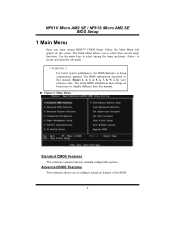
... BIOS. 4 The actual BIOS information and settings on the screen. Advanced BIOS Features This submenu allows you to accept and enter the sub-menu. !! The BIOS information described in this manual. „ Figure 1: Main Menu Standard CMOS Features This submenu contains industry standard configurable options. For better system performance, the BIOS firmware is for your reference only. WARNING !! NF61V Micro AM2 SE / NF61S Micro AM2 SE BIOS Setup 1 Main Menu Once you enter Award BIOS™ CMOS Setup Utility, the Main Menu will appear on board...
... BIOS. 4 The actual BIOS information and settings on the screen. Advanced BIOS Features This submenu allows you to accept and enter the sub-menu. !! The BIOS information described in this manual. „ Figure 1: Main Menu Standard CMOS Features This submenu contains industry standard configurable options. For better system performance, the BIOS firmware is for your reference only. WARNING !! NF61V Micro AM2 SE / NF61S Micro AM2 SE BIOS Setup 1 Main Menu Once you enter Award BIOS™ CMOS Setup Utility, the Main Menu will appear on board...
Setup Manual
Page 60
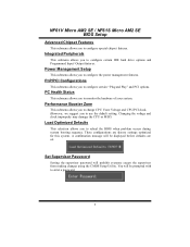
... supervisor from making changes using the CMOS Setup Utility. NF61V Micro AM2 SE / NF61S Micro AM2 SE BIOS Setup Advanced Chipset Features This submenu allows you to enter a password. 5 Integrated Peripherals This submenu allows you to configure cert ain IDE hard drive options and Programmed Input/ Output features. These configurations are set. PnP/PCI Configurations This submenu allows you to configure cert ain " Plug and Play" and PCI options. Changing the voltage and clock improperly may damage the CPU or M/B!) Load Optimized Defaults This selection allows...
... supervisor from making changes using the CMOS Setup Utility. NF61V Micro AM2 SE / NF61S Micro AM2 SE BIOS Setup Advanced Chipset Features This submenu allows you to enter a password. 5 Integrated Peripherals This submenu allows you to configure cert ain IDE hard drive options and Programmed Input/ Output features. These configurations are set. PnP/PCI Configurations This submenu allows you to configure cert ain " Plug and Play" and PCI options. Changing the voltage and clock improperly may damage the CPU or M/B!) Load Optimized Defaults This selection allows...

Setup Manual
Page 65
Disabled Disable cache. Enabled (default) Enable cache. Enabled (default) Enable cache. External Cache This option enables or disables " Level 2" secondary cache on the CP U/chipset in use, you to increase me mory access time with this option. Disabled Disable cache. Boot Seq & Floppy Setup This item allows you may improve performance. NF61V Micro AM2 SE / NF61S Micro AM2 SE BIOS Setup CPU Internal Cache Depending on the CP U, which may be able to setup boot sequence & Floppy. 10
Disabled Disable cache. Enabled (default) Enable cache. Enabled (default) Enable cache. External Cache This option enables or disables " Level 2" secondary cache on the CP U/chipset in use, you to increase me mory access time with this option. Disabled Disable cache. Boot Seq & Floppy Setup This item allows you may improve performance. NF61V Micro AM2 SE / NF61S Micro AM2 SE BIOS Setup CPU Internal Cache Depending on the CP U, which may be able to setup boot sequence & Floppy. 10
Setup Manual
Page 67
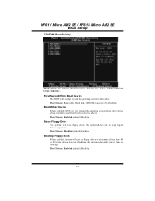
... or 80 tracks during boot up . First/Second/Third Boot Dev ice The BIOS will try to load the operating system from the three devices above. Boot Other Dev ice When enabled, BIOS will attempt to swap logical drive assignments. Master, Sec. Master, Pri. Slave, Sec. The Choices: Enabled (default), Disabled. 12 NF61V Micro AM2 SE / NF61S Micro AM2 SE BIOS Setup CD-ROM Boot Priority TheChoices: Pri. The Choices: Removable, Hard Disk, CDROM, Legacy LAN, Disabled. Disabling this order.
... or 80 tracks during boot up . First/Second/Third Boot Dev ice The BIOS will try to load the operating system from the three devices above. Boot Other Dev ice When enabled, BIOS will attempt to swap logical drive assignments. Master, Sec. Master, Pri. Slave, Sec. The Choices: Enabled (default), Disabled. 12 NF61V Micro AM2 SE / NF61S Micro AM2 SE BIOS Setup CD-ROM Boot Priority TheChoices: Pri. The Choices: Removable, Hard Disk, CDROM, Legacy LAN, Disabled. Disabling this order.
Setup Manual
Page 68
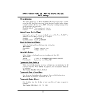
... A pin in the keyboard controller controls GateA20. When enabled, the typematic rate and typematic delay can be configured. The Choices: 6 (default), 8, 10, 12, 15, 20, 24, 30. Typematic Dela y (Msec) Sets the delay time after the key is held down, the keystroke will display a warning message on . The Choices: 250 (default), 500, 750, 1000. 13 The Choices: Disabled (default), Enabled. NF61V Micro AM2 SE / NF61S Micro AM2 SE BIOS Setup Virus Warning This option...
... A pin in the keyboard controller controls GateA20. When enabled, the typematic rate and typematic delay can be configured. The Choices: 6 (default), 8, 10, 12, 15, 20, 24, 30. Typematic Dela y (Msec) Sets the delay time after the key is held down, the keystroke will display a warning message on . The Choices: 250 (default), 500, 750, 1000. 13 The Choices: Disabled (default), Enabled. NF61V Micro AM2 SE / NF61S Micro AM2 SE BIOS Setup Virus Warning This option...
Setup Manual
Page 69
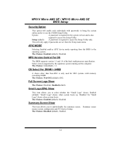
... Version Control For OS The BIOS supports version 1.1 and 1.4 of the Intel multiprocessor speci fication. Enabled (default) " Small Logo" shows when system boots up. The Choices: Non-OS2 (default), OS2. Summary screen means system configuration and PCI device listing. Disabled No "Small Logo" shows when system boots The Choices: Enabled (default), Disabled Summary Screen Show This item allows you to access the Setup Utility only. NF61V Micro AM2 SE / NF61S Micro AM2 SE BIOS Setup Security Option This option will only apply if passwords are set...
... Version Control For OS The BIOS supports version 1.1 and 1.4 of the Intel multiprocessor speci fication. Enabled (default) " Small Logo" shows when system boots up. The Choices: Non-OS2 (default), OS2. Summary screen means system configuration and PCI device listing. Disabled No "Small Logo" shows when system boots The Choices: Enabled (default), Disabled Summary Screen Show This item allows you to access the Setup Utility only. NF61V Micro AM2 SE / NF61S Micro AM2 SE BIOS Setup Security Option This option will only apply if passwords are set...
Setup Manual
Page 70
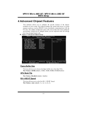
... not be changed unless you are suspicious that came with the PCI bus. K8NB HT Speed This item allows you to choose the frame buffer size of the chipset installed on -chip VGA. This chipset manage bus speeds and access to system memory resources, such as DRAM. It also coordinates communications with your system. The Choices: Auto (default), 1x, 2x, 3x, 4x, 5x. 15 NF61V Micro AM2 SE / NF61S Micro AM2 SE BIOS Setup 4 Advanced Chipset Features...
... not be changed unless you are suspicious that came with the PCI bus. K8NB HT Speed This item allows you to choose the frame buffer size of the chipset installed on -chip VGA. This chipset manage bus speeds and access to system memory resources, such as DRAM. It also coordinates communications with your system. The Choices: Auto (default), 1x, 2x, 3x, 4x, 5x. 15 NF61V Micro AM2 SE / NF61S Micro AM2 SE BIOS Setup 4 Advanced Chipset Features...
Setup Manual
Page 71
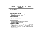
... " Enabled" option allows caching of the system BIOS ROM at F0000h-FFFFFh, which is able to enable/disable SSE/SSE2 instruction. The choices: Disabled (default), Center, Down. SATA /PCIE Spread Spectrum This item allows you to this memory block will cause conflicts and result in system errors. However, any programs that attempts to write to enable/disable the Spread Spectrum function. The Choices: Disabled (default), Enabled. The Choices: Enabled (default), Disabled...
... " Enabled" option allows caching of the system BIOS ROM at F0000h-FFFFFh, which is able to enable/disable SSE/SSE2 instruction. The choices: Disabled (default), Center, Down. SATA /PCIE Spread Spectrum This item allows you to this memory block will cause conflicts and result in system errors. However, any programs that attempts to write to enable/disable the Spread Spectrum function. The Choices: Disabled (default), Enabled. The Choices: Enabled (default), Disabled...

Setup Manual
Page 73
... Mode0, Mode1, Mode2, Mode3, Mode4. 18 The Choices: Disabled (default), Enabled. Select " Enabled" to enable or disable RAID function. On-chip IDE Channel 0 The motherboard chipset contains a P CI IDE interface with support for each device. The Choices: Disabled (default), Enabled. The Choices: Enabled (default), Disabled. Primary Master/Slave PIO The IDE P IO (P rogrammed Input / Output) fields let you set a P IO mode (0-4) for two IDE channels. NF61V Micro AM2 SE / NF61S Micro AM2 SE BIOS Setup RAID Config RAID Enable This option allows you to activate the first and/or...
... Mode0, Mode1, Mode2, Mode3, Mode4. 18 The Choices: Disabled (default), Enabled. Select " Enabled" to enable or disable RAID function. On-chip IDE Channel 0 The motherboard chipset contains a P CI IDE interface with support for each device. The Choices: Disabled (default), Enabled. The Choices: Enabled (default), Disabled. Primary Master/Slave PIO The IDE P IO (P rogrammed Input / Output) fields let you set a P IO mode (0-4) for two IDE channels. NF61V Micro AM2 SE / NF61S Micro AM2 SE BIOS Setup RAID Config RAID Enable This option allows you to activate the first and/or...

Setup Manual
Page 74
... Disabled,SATA-1,SATA-2 IDE Prefetch Mode The " onboard" IDE drive interfaces supports IDE prefetch function for Serial-ATA controller. If the interface on your system software both support Ultra DMA, select Auto to enable BIOS support. The Choices: Auto (default), Disabled. Serial-ATA Controller Enables support for faster drive access. If your hard drive and your drive does not support prefetching, or if you to " Disabled". As well, your system. The Choices: Enabled (default), Disabled. The Choices: Enabled (default), Disabled. 19 NF61V Micro AM2 SE / NF61S Micro AM2 SE BIOS...
... Disabled,SATA-1,SATA-2 IDE Prefetch Mode The " onboard" IDE drive interfaces supports IDE prefetch function for Serial-ATA controller. If the interface on your system software both support Ultra DMA, select Auto to enable BIOS support. The Choices: Auto (default), Disabled. Serial-ATA Controller Enables support for faster drive access. If your hard drive and your drive does not support prefetching, or if you to " Disabled". As well, your system. The Choices: Enabled (default), Disabled. The Choices: Enabled (default), Disabled. 19 NF61V Micro AM2 SE / NF61S Micro AM2 SE BIOS...

Setup Manual
Page 76
... second serial ports. The Choices: Disabled (default), Enabled. Onboard I/O Address Onboard FDC Controller Select enabled if your system has a floppy disk controller (FDC) installed on the system board and you wish to control the onboard MAC LAN. If you installed another FDC or the system uses no floppy drive, select disabled in this field. The Choices: Auto (default), Disabled. The Choices: 3F8/IRQ4 (default), Disabled, 2F8/IRQ3, 3E8/IRQ4, 2E8/IRQ3, Auto. 21 The Choices: Enabled (default), Disabled. NF61V Micro AM2 SE / NF61S Micro AM2 SE BIOS Setup MAC LAN This option...
... second serial ports. The Choices: Disabled (default), Enabled. Onboard I/O Address Onboard FDC Controller Select enabled if your system has a floppy disk controller (FDC) installed on the system board and you wish to control the onboard MAC LAN. If you installed another FDC or the system uses no floppy drive, select disabled in this field. The Choices: Auto (default), Disabled. The Choices: 3F8/IRQ4 (default), Disabled, 2F8/IRQ3, 3E8/IRQ4, 2E8/IRQ3, Auto. 21 The Choices: Enabled (default), Disabled. NF61V Micro AM2 SE / NF61S Micro AM2 SE BIOS Setup MAC LAN This option...

Setup Manual
Page 77
... P ort. Init Display First With systems that have multiple video cards, this feature i f you to determine access onboard parallel port controller with which I/O Address. The Choices: V1.1+V2.0 (default), Disabled, V1.1 IDE HDD Block Mode Block mode is SPP . ECP +EPP Using P arallel port as Enhanced P arallel Port. The Choices: PCI-Express (default),PCI Slot, Onboard. The Choices: Enabled (default), Disabled. 22 EPP Using P arallel P ort as ECP & EPP mode. The Choices: Auto (default), Always Enable. OnChip USB T his option should function.
... P ort. Init Display First With systems that have multiple video cards, this feature i f you to determine access onboard parallel port controller with which I/O Address. The Choices: V1.1+V2.0 (default), Disabled, V1.1 IDE HDD Block Mode Block mode is SPP . ECP +EPP Using P arallel port as Enhanced P arallel Port. The Choices: PCI-Express (default),PCI Slot, Onboard. The Choices: Enabled (default), Disabled. 22 EPP Using P arallel P ort as ECP & EPP mode. The Choices: Auto (default), Always Enable. OnChip USB T his option should function.

Setup Manual
Page 82
... term, which allows I/O devices to the memory locations. The system needs to record and update ESCD to operate at speeds nearing the speed of the CPU itself uses when communicating with its own special components. If the Disabled (default) option is called ESCD. Every peripheral device has a node, which resources are reserved in the system BIOS. NF61V Micro AM2 SE / NF61S Micro AM2 SE BIOS Setup 7 PnP/PCI Configurations This section describes configuring the PCI bus system.
... term, which allows I/O devices to the memory locations. The system needs to record and update ESCD to operate at speeds nearing the speed of the CPU itself uses when communicating with its own special components. If the Disabled (default) option is called ESCD. Every peripheral device has a node, which resources are reserved in the system BIOS. NF61V Micro AM2 SE / NF61S Micro AM2 SE BIOS Setup 7 PnP/PCI Configurations This section describes configuring the PCI bus system.


