

M7VKQ user's manual
Page 3
... 1-2 1.1.1 Hardware...1-2 1.1.2 Software...1-6 1.1.3 Accessories ...1-6 1.2 Motherboard Installation 1-7 1.2.1 System Block Diagram 1-7 1.2.2 Layout of Motherboard 1-8 1.2.3 Quick Reference 1-9 1.3 CPU Installation 1-10 1.3.1 CPU Installation Procedure: Socket A 1-10 1.3.2 Frequency Selection: JCLK1 1-11 1.3.3 CPU Fan Connector: JCFAN1 1-12 1.3.4 System Fan Connector: JSFAN1 1-12 1.3.5 North ...
... 1-2 1.1.1 Hardware...1-2 1.1.2 Software...1-6 1.1.3 Accessories ...1-6 1.2 Motherboard Installation 1-7 1.2.1 System Block Diagram 1-7 1.2.2 Layout of Motherboard 1-8 1.2.3 Quick Reference 1-9 1.3 CPU Installation 1-10 1.3.1 CPU Installation Procedure: Socket A 1-10 1.3.2 Frequency Selection: JCLK1 1-11 1.3.3 CPU Fan Connector: JCFAN1 1-12 1.3.4 System Fan Connector: JSFAN1 1-12 1.3.5 North ...
M7VKQ user's manual
Page 6
M7VKQ Highlights: 8 Contains on board I/O facilities, which brings to provide you the latest technology in microarchitecture design, graphics performance, system bus design, cache architecture and much ... reliability, performance and strives for IDE devices such as Windows 95/98, Windows NT, Windows 2000, Windows ME, Windows XP, LINUX and SCO UNIX. 1-1 This motherboard is designed to take advantage of the latest industry technology to you with industry software and hardware standards. In the tradition of its predecessors, this...
M7VKQ Highlights: 8 Contains on board I/O facilities, which brings to provide you the latest technology in microarchitecture design, graphics performance, system bus design, cache architecture and much ... reliability, performance and strives for IDE devices such as Windows 95/98, Windows NT, Windows 2000, Windows ME, Windows XP, LINUX and SCO UNIX. 1-1 This motherboard is designed to take advantage of the latest industry technology to you with industry software and hardware standards. In the tradition of its predecessors, this...

M7VKQ user's manual
Page 7
... DIMM module socket. − Supports Synchronous DRAM (3.3V). − Support a maximum memory size of any key or any mouse activity. 1-2 Motherboard Description 1.1 Features 1.1.1 Hardware CPU − − Single AMD Socket-A for Athlon TM (Thunderbird TM )/ Athlon TM XP/ Duron TM processors... − Wakes from 1 to AMD Athlon TM XP 2000+ CPU core speeds. VIA VT8361/ VT82C686B. − Chipset - Chapter 1 Motherboard Description 1. LAN Chip Realtek RTL 8100 (Optional). Shadow RAM − A memory controller provide shadow RAM and supports 8-bit ROM BIOS. Chipset −...
... DIMM module socket. − Supports Synchronous DRAM (3.3V). − Support a maximum memory size of any key or any mouse activity. 1-2 Motherboard Description 1.1 Features 1.1.1 Hardware CPU − − Single AMD Socket-A for Athlon TM (Thunderbird TM )/ Athlon TM XP/ Duron TM processors... − Wakes from 1 to AMD Athlon TM XP 2000+ CPU core speeds. VIA VT8361/ VT82C686B. − Chipset - Chapter 1 Motherboard Description 1. LAN Chip Realtek RTL 8100 (Optional). Shadow RAM − A memory controller provide shadow RAM and supports 8-bit ROM BIOS. Chipset −...
M7VKQ user's manual
Page 8
... 33/ 66/100 Bus Master Mode. − Supports IDE interface with CD-ROM. − Supports high capacity hard disk drives. − Supports LBA mode. Chapter 1 Motherboard Description BUS Slots − Three 32-bit PCI bus master slots. − One ISA slot. − One AMR slot. Flash Memory − Supports flash memory...
... 33/ 66/100 Bus Master Mode. − Supports IDE interface with CD-ROM. − Supports high capacity hard disk drives. − Supports LBA mode. Chapter 1 Motherboard Description BUS Slots − Three 32-bit PCI bus master slots. − One ISA slot. − One AMR slot. Flash Memory − Supports flash memory...

M7VKQ user's manual
Page 9
...-up to store resource configuration, ID parameter, and VPD data. − Supports LED pins for various network activity indications. − Half/ Full duplex capability. Chapter 1 Motherboard Description LAN Built-in one chip. − PCI local bus single-chip Fast Ethernet controller. − Compliant to PCI Revision 2.2 − Supports ACPI, PCI power...
...-up to store resource configuration, ID parameter, and VPD data. − Supports LED pins for various network activity indications. − Half/ Full duplex capability. Chapter 1 Motherboard Description LAN Built-in one chip. − PCI local bus single-chip Fast Ethernet controller. − Compliant to PCI Revision 2.2 − Supports ACPI, PCI power...

M7VKQ user's manual
Page 10
Chapter 1 Motherboard Description − Multiple buffering and page flipping Universal Serial Bus − Supports two back Universal Serial Bus (USB) Ports and two front Universal serial Bus (USB) Ports (Optional). − Supports 48 MHz USB. Dimensions (Micro ATX) − 19.8 cm X 24.4 cm (W x L) 1-5 Hardware Monitor Function − CPU Fan and System Fan Speed Monitor. − System and CPU Temperature Monitor (Optional). − System Voltage Monitor.
Chapter 1 Motherboard Description − Multiple buffering and page flipping Universal Serial Bus − Supports two back Universal Serial Bus (USB) Ports and two front Universal serial Bus (USB) Ports (Optional). − Supports 48 MHz USB. Dimensions (Micro ATX) − 19.8 cm X 24.4 cm (W x L) 1-5 Hardware Monitor Function − CPU Fan and System Fan Speed Monitor. − System and CPU Temperature Monitor (Optional). − System Voltage Monitor.
M7VKQ user's manual
Page 11
Supports USB Function. Chapter 1 Motherboard Description 1.1.2 Software BIOS AWARD legal BIOS. Operating System − Offers the highest performance for MS-DOS, Windows NT, Windows 2000, Windows 95/98, Windows ME, Windows XP, SCO UNIX etc. 1.1.3 Accessories − HDD Cable. − FDD Cable. − Flash Memory Writer for BIOS Update. − USB2 Cable (Optional). − Rear I/O Panel for Micro ATX Case (Optional). − Fully Setup Driver CD. 1-6 Supports ACPI. Supports APM1.2.
Supports USB Function. Chapter 1 Motherboard Description 1.1.2 Software BIOS AWARD legal BIOS. Operating System − Offers the highest performance for MS-DOS, Windows NT, Windows 2000, Windows 95/98, Windows ME, Windows XP, SCO UNIX etc. 1.1.3 Accessories − HDD Cable. − FDD Cable. − Flash Memory Writer for BIOS Update. − USB2 Cable (Optional). − Rear I/O Panel for Micro ATX Case (Optional). − Fully Setup Driver CD. 1-6 Supports ACPI. Supports APM1.2.
M7VKQ user's manual
Page 12
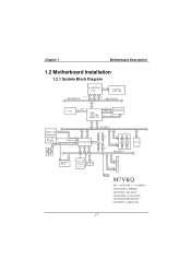
M7VKQ Micro ATX(FSB: 133/100MHz) SUPPORTS 2 DIMMS SUPPORT 1 ISA SLOT SUPPORTS 3 PCI SLOTS SUPPORT TELEPHONY SUPPORT 1 AMR SLOT 1-7 PG. 7 CNTL PG. 13 US B US B US B US B A D D R/ D ATA PG. 7 ISA BUS PCI Slot PCI Slot PCI Slot LAN RT L 81 00B ISA Slot K E Y BO A RD MOUSE FLOPPY CONN. Chapter 1 Motherboard Description 1.2 Motherboard Installation 1.2.1 System...
M7VKQ Micro ATX(FSB: 133/100MHz) SUPPORTS 2 DIMMS SUPPORT 1 ISA SLOT SUPPORTS 3 PCI SLOTS SUPPORT TELEPHONY SUPPORT 1 AMR SLOT 1-7 PG. 7 CNTL PG. 13 US B US B US B US B A D D R/ D ATA PG. 7 ISA BUS PCI Slot PCI Slot PCI Slot LAN RT L 81 00B ISA Slot K E Y BO A RD MOUSE FLOPPY CONN. Chapter 1 Motherboard Description 1.2 Motherboard Installation 1.2.1 System...

M7VKQ user's manual
Page 13
FLOPPY DISK CONN. Chapter 1 Motherboard Description 1.2.2 Layout of Motherboard Model No. SECONDARY IDE CONN. M7VKQ JKBMS1 K/B & Mouse JLAN USB & LAN JCOM1 JKBV1 1 SOCKET A 1 JCFAN1 BAT1 JCMOS1 1 COM1 Parallel Port CPU1 JCLK1 1 DIMM1 DIMM2 VGA1 PRIMARY IDE CONN. JPRNT1 JVGA1 SPKR-OUT JATXPWR1 VT8361 GAME Port LINE-IN JCDIN1 MIC-IN AUD_GAME1 1 AMR SLOT JAMRS1 1 JTAD1 1 AMR1 JAUDIO1 2 10 JWOL1 PCI BUS SLOT 19 1 PCI BUS SLOT U1 JNFAN1 1 PCI1 PCI2 PCI3 PCI BUS SLOT ISA1 ISA SLOT IDE1 IDE2 FDD1 1 JSFAN1 VT82C686 BIOS U2 JPANEL1 2 10 1 9 JUSB2 1-8
FLOPPY DISK CONN. Chapter 1 Motherboard Description 1.2.2 Layout of Motherboard Model No. SECONDARY IDE CONN. M7VKQ JKBMS1 K/B & Mouse JLAN USB & LAN JCOM1 JKBV1 1 SOCKET A 1 JCFAN1 BAT1 JCMOS1 1 COM1 Parallel Port CPU1 JCLK1 1 DIMM1 DIMM2 VGA1 PRIMARY IDE CONN. JPRNT1 JVGA1 SPKR-OUT JATXPWR1 VT8361 GAME Port LINE-IN JCDIN1 MIC-IN AUD_GAME1 1 AMR SLOT JAMRS1 1 JTAD1 1 AMR1 JAUDIO1 2 10 JWOL1 PCI BUS SLOT 19 1 PCI BUS SLOT U1 JNFAN1 1 PCI1 PCI2 PCI3 PCI BUS SLOT ISA1 ISA SLOT IDE1 IDE2 FDD1 1 JSFAN1 VT82C686 BIOS U2 JPANEL1 2 10 1 9 JUSB2 1-8

M7VKQ user's manual
Page 14
... (FDD1) C. Frequency Selection (JCLK1) E. PCI BUS Slots (PCI1-3) R. ISA BUS Slot (ISA1) S. CPU FAN Header (JCFAN1) H. Front Audio Header (JAUDIO1) Q. Front Panel Connector (JPANEL1) U. Chapter 1 Motherboard Description 1.2.3 Quick Reference U TS R Q P A O N M B C D L K E F G J H I A. North Bridge Fan Header (JNFAN1)* B. Wake-On-LAN Header (JWOL1) P. System FAN Header (JSFAN1)* Note: The " * " mark means that the function...
... (FDD1) C. Frequency Selection (JCLK1) E. PCI BUS Slots (PCI1-3) R. ISA BUS Slot (ISA1) S. CPU FAN Header (JCFAN1) H. Front Audio Header (JAUDIO1) Q. Front Panel Connector (JPANEL1) U. Chapter 1 Motherboard Description 1.2.3 Quick Reference U TS R Q P A O N M B C D L K E F G J H I A. North Bridge Fan Header (JNFAN1)* B. Wake-On-LAN Header (JWOL1) P. System FAN Header (JSFAN1)* Note: The " * " mark means that the function...

M7VKQ user's manual
Page 15
Put the fan on the CPU by buckling it, and then put the fan's powerport into the JCFAN1, then the installation will be completed. 1-10 Pull the lever sideways away from the socket then raise the lever up to a 90-degree angle. 2. Press the lever down . 4. Chapter 1 Motherboard Description 1.3 CPU Installation 1.3.1 CPU Installation Procedure: Socket A CPU 1. Locate Pin A in the CPU. Match Pin A with the white dot/cut edge in the socket and look for the white dot or cut edge then insert the CPU. 3.
Put the fan on the CPU by buckling it, and then put the fan's powerport into the JCFAN1, then the installation will be completed. 1-10 Pull the lever sideways away from the socket then raise the lever up to a 90-degree angle. 2. Press the lever down . 4. Chapter 1 Motherboard Description 1.3 CPU Installation 1.3.1 CPU Installation Procedure: Socket A CPU 1. Locate Pin A in the CPU. Match Pin A with the white dot/cut edge in the socket and look for the white dot or cut edge then insert the CPU. 3.

M7VKQ user's manual
Page 16
Chapter 1 SOCKET A Motherboard Description J C FA N 1 1 VT8361 DIMM1 DIMM2 JCLK1 1 VT82C686 BIOS JS FA N 1 1 JNFAN1 1 1.3.2 CPU Frequency Selection: JCLK1 JCKL1 *100MHz 1-2 133MHz 2-3 NOTES: The " * " mark indicate primitive value. 1-11
Chapter 1 SOCKET A Motherboard Description J C FA N 1 1 VT8361 DIMM1 DIMM2 JCLK1 1 VT82C686 BIOS JS FA N 1 1 JNFAN1 1 1.3.2 CPU Frequency Selection: JCLK1 JCKL1 *100MHz 1-2 133MHz 2-3 NOTES: The " * " mark indicate primitive value. 1-11

M7VKQ user's manual
Page 17
Chapter 1 Motherboard Description 1.3.3 CPU Fan Connector: JCFAN1 Pin No. 1 2 3 Assignment Ground +12V Sense 1.3.4 System Fan Connector: JSFAN1 (Optional) Pin No. 1 2 3 Assignment Ground +12V Sense 1.3.5 North Bridge Chipset Fan Header: JNFAN1 (Optional) Pin No. 1 2 Assignment Ground +12V 1-12
Chapter 1 Motherboard Description 1.3.3 CPU Fan Connector: JCFAN1 Pin No. 1 2 3 Assignment Ground +12V Sense 1.3.4 System Fan Connector: JSFAN1 (Optional) Pin No. 1 2 3 Assignment Ground +12V Sense 1.3.5 North Bridge Chipset Fan Header: JNFAN1 (Optional) Pin No. 1 2 Assignment Ground +12V 1-12

M7VKQ user's manual
Page 18
Chapter 1 Motherboard Description 1.4 RAM Module Installation 1.4.1 DIMM DRAM Access Time: 3.3V Unbuffered SDRAM PC66/ PC100 and PC133 Type required. DRAM Type: 32MB/ 64MB/ 128MB/ 256MB/ 512MB DIMM ...
Chapter 1 Motherboard Description 1.4 RAM Module Installation 1.4.1 DIMM DRAM Access Time: 3.3V Unbuffered SDRAM PC66/ PC100 and PC133 Type required. DRAM Type: 32MB/ 64MB/ 128MB/ 256MB/ 512MB DIMM ...

M7VKQ user's manual
Page 19
The Mounting Holes and plastic tabs should fit over the edge and hold the DIMM memory modules in one direction. 2. Chapter 1 Motherboard Description 1.4.2 How to install a DIMM Module 1. Insert the DIMM memory modules into the socket at a 90-degree angle, and then push down vertically so that it will fit into the slot in place. 1-14 The DIMM socket has a " Plastic Safety Tab", and the DIMM memory module has an "Asymmetrical notch", so the DIMM memory module can only fit into the place. 3. Push the tabs out.
The Mounting Holes and plastic tabs should fit over the edge and hold the DIMM memory modules in one direction. 2. Chapter 1 Motherboard Description 1.4.2 How to install a DIMM Module 1. Insert the DIMM memory modules into the socket at a 90-degree angle, and then push down vertically so that it will fit into the slot in place. 1-14 The DIMM socket has a " Plastic Safety Tab", and the DIMM memory module has an "Asymmetrical notch", so the DIMM memory module can only fit into the place. 3. Push the tabs out.

M7VKQ user's manual
Page 20
Expansion slots are designed to hold expansion cards and connect them to the system bus. Chapter 1 Motherboard Description 1.5 Slots The slots in this motherboard are a mean of the basic system. With these efficient facilities, you can increase the motherboard's capabilities by adding hardware that performs tasks that are not part of adding or enhancing the motherboard's features and capabilities. SOCKET A DIMM1 DIMM2 AMR Slot PCI Slots ISA Slot VT8361 VT82C686 BIOS 1-15
Expansion slots are designed to hold expansion cards and connect them to the system bus. Chapter 1 Motherboard Description 1.5 Slots The slots in this motherboard are a mean of the basic system. With these efficient facilities, you can increase the motherboard's capabilities by adding hardware that performs tasks that are not part of adding or enhancing the motherboard's features and capabilities. SOCKET A DIMM1 DIMM2 AMR Slot PCI Slots ISA Slot VT8361 VT82C686 BIOS 1-15

M7VKQ user's manual
Page 21
... Architecture that defines a hardware scalable riser card interface, which only supports audio and modem. 1.5.2 PCI (Peripheral Component Interconnect) Slots This motherboard is equipped with one standard ISA slot. PCI stands for Peripheral Component Interconnect, and it was designed as 32 bits. 1.5.3 ISA (...Industry Standard Architecture) Slot The motherboard is equipped with this older and slower bus architecture. 1-16 This PCI slot is designated as a bus standard for PC XT/AT...
... Architecture that defines a hardware scalable riser card interface, which only supports audio and modem. 1.5.2 PCI (Peripheral Component Interconnect) Slots This motherboard is equipped with one standard ISA slot. PCI stands for Peripheral Component Interconnect, and it was designed as 32 bits. 1.5.3 ISA (...Industry Standard Architecture) Slot The motherboard is equipped with this older and slower bus architecture. 1-16 This PCI slot is designated as a bus standard for PC XT/AT...

M7VKQ user's manual
Page 22
JKBV1 1 JATXPWR1 JWOL1 1 JAMRS1 1 SOCKET A VT8361 DIMM1 DIMM2 JCMOS1 1 IDE 1-2 FDD1 VT82C686 BIOS JPANEL1 JUSB2 2 10 1 9 1-17 Chapter 1 Motherboard Description 1.6 Connectors, Headers & Jumpers The connectors, headers and jumpers introduced below provide you lots of capabilities such as power supply, front panel signal revelation, IDE hard disk connection, floppy disk connection, Wake On LAN function and USB connection. Noticeably, a jumper has two or more pins covered by a plastic jumper cap, allowing the user to select a different system options.
JKBV1 1 JATXPWR1 JWOL1 1 JAMRS1 1 SOCKET A VT8361 DIMM1 DIMM2 JCMOS1 1 IDE 1-2 FDD1 VT82C686 BIOS JPANEL1 JUSB2 2 10 1 9 1-17 Chapter 1 Motherboard Description 1.6 Connectors, Headers & Jumpers The connectors, headers and jumpers introduced below provide you lots of capabilities such as power supply, front panel signal revelation, IDE hard disk connection, floppy disk connection, Wake On LAN function and USB connection. Noticeably, a jumper has two or more pins covered by a plastic jumper cap, allowing the user to select a different system options.

M7VKQ user's manual
Page 23
... The speaker (onboard or offboard) provides error beep code information during the Power On Self-Test when the computer cannot use the video interface. Chapter 1 Motherboard Description 1.6.1 Front Panel Connector: JPANEL1 K SLP POW-LED ON/OFF E IR (+) (+) (-) Y 2 24 1 23 SPK (+) (-) HLED RST NA Pin Assignment No. 1 +5V 3 NA 5 NA 7 Speaker 9 ...Ground 24 IRRX Function Sleep Button NA POWER LED Power-on Button IrDA Connector SPK (Speaker Connector) An offboard speaker can be installed on the motherboard as a manufacturing option. The speaker is not connected to the...
... The speaker (onboard or offboard) provides error beep code information during the Power On Self-Test when the computer cannot use the video interface. Chapter 1 Motherboard Description 1.6.1 Front Panel Connector: JPANEL1 K SLP POW-LED ON/OFF E IR (+) (+) (-) Y 2 24 1 23 SPK (+) (-) HLED RST NA Pin Assignment No. 1 +5V 3 NA 5 NA 7 Speaker 9 ...Ground 24 IRRX Function Sleep Button NA POWER LED Power-on Button IrDA Connector SPK (Speaker Connector) An offboard speaker can be installed on the motherboard as a manufacturing option. The speaker is not connected to the...
M7VKQ user's manual
Page 24
... and the hard disk when is not in the system BIOS, and the APM driver must pass before the power supply will cause the motherboard to and from the front panel to an infrared sensing device. The LED will flicker during disk activity where it is only applied to ... least two seconds must be loaded. This switch is usually open, and when it will recognize another on the front panel of a computer case. Chapter 1 Motherboard Description RST (Reset Button) This connector can be attached to a front panel power switch. PWR (Power Button) This connector can be attached to a momentary...
... and the hard disk when is not in the system BIOS, and the APM driver must pass before the power supply will cause the motherboard to and from the front panel to an infrared sensing device. The LED will flicker during disk activity where it is only applied to ... least two seconds must be loaded. This switch is usually open, and when it will recognize another on the front panel of a computer case. Chapter 1 Motherboard Description RST (Reset Button) This connector can be attached to a front panel power switch. PWR (Power Button) This connector can be attached to a momentary...


