
M7VIG Pro D user's manual
Page 5
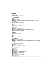
Maximum memory size of 2GB. On Board IDE Supports four IDE disk drives. Slots Three 32-bits PCI bus master slots. Compliant with AC'97 specification. Rear side 1 serial port. 1 VGA port. 1 parallel port. (SPP/EPP/ECP mode) 1 Audio port in vertical position. 1 LAN jack. Supports single AMD® for Athlon™ (Thunderbird™)/ Athlon™ XP/ Duron™ processors. Front Side Bus at 200/266 MHz. Main Memory Supports up to 2 DDR devices. PS/2 mouse and PS/2 keyboard. 4 USB2.0 ports. b. Chipset North Bridge: VIA...
Maximum memory size of 2GB. On Board IDE Supports four IDE disk drives. Slots Three 32-bits PCI bus master slots. Compliant with AC'97 specification. Rear side 1 serial port. 1 VGA port. 1 parallel port. (SPP/EPP/ECP mode) 1 Audio port in vertical position. 1 LAN jack. Supports single AMD® for Athlon™ (Thunderbird™)/ Athlon™ XP/ Duron™ processors. Front Side Bus at 200/266 MHz. Main Memory Supports up to 2 DDR devices. PS/2 mouse and PS/2 keyboard. 4 USB2.0 ports. b. Chipset North Bridge: VIA...
M7VIG Pro D user's manual
Page 8
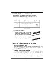
... slot. 2. Hard Disk Connectors: IDE1/ IDE2 The motherboard has a 32-bit Enhanced PCI IDE Controller that the notch on the DIMM matches the break on the slot such that provides PIO Mode 0~4, Bus Master, and Ultra DMA 33/ 66/ 100/ 133 functionality. The first hard drive should always be connected to four hard disk drives. It has two HDD connectors IDE1 (primary) and IDE2 (secondary). DDR DIMM Modules: DDR1/ DDR2 DRAM Access...
... slot. 2. Hard Disk Connectors: IDE1/ IDE2 The motherboard has a 32-bit Enhanced PCI IDE Controller that the notch on the DIMM matches the break on the slot such that provides PIO Mode 0~4, Bus Master, and Ultra DMA 33/ 66/ 100/ 133 functionality. The first hard drive should always be connected to four hard disk drives. It has two HDD connectors IDE1 (primary) and IDE2 (secondary). DDR DIMM Modules: DDR1/ DDR2 DRAM Access...

M7VIG Pro D user's manual
Page 11
... ". 3. Set the jumper to support this function "Power-on the system via USB device", "JUSBV1/JUSBV2/JUSBV3" jumper cap should be placed on pin 2-3 respectively. Clear CMOS Jumper: JCMOS1 JCMOS1 3 1 Pin 1-2 Close 3 1 Pin 2-3 Close Assignment Normal Operation (default) Clear CMOS Data The following procedures are for five seconds. 4. Power Source Selection for USB: JUSBV1/ JUSBV2/ JUSBV3 JUSBV1/ JUSBV2/ JUSBV3 Assignment Description 1 3 Pin 1-2 close JUSBV2: 5V for USB located at the JUSB4 port...
... ". 3. Set the jumper to support this function "Power-on the system via USB device", "JUSBV1/JUSBV2/JUSBV3" jumper cap should be placed on pin 2-3 respectively. Clear CMOS Jumper: JCMOS1 JCMOS1 3 1 Pin 1-2 Close 3 1 Pin 2-3 Close Assignment Normal Operation (default) Clear CMOS Data The following procedures are for five seconds. 4. Power Source Selection for USB: JUSBV1/ JUSBV2/ JUSBV3 JUSBV1/ JUSBV2/ JUSBV3 Assignment Description 1 3 Pin 1-2 close JUSBV2: 5V for USB located at the JUSB4 port...

M7VIG Pro D user's manual
Page 25
... Hardware Monitor smartly indicates the temperatures, voltage and CPU fan speed as well as the chipset information. System Requirement OS Support: Windows 98 SE, Windows Me, Windows 2000, Windows XP DirectX: DirectX 8.1 or above. (The Windows XP operating system includes DirectX 8.1. WarpSpeeder Introduction [ WarpSpeeder™ ], a new powerful control utility, features three user-friendly functions including Overclock Manager, Overvoltage Manager, and Hardware Monitor. With the Overclock Manager, users can easily adjust the frequency they...
... Hardware Monitor smartly indicates the temperatures, voltage and CPU fan speed as well as the chipset information. System Requirement OS Support: Windows 98 SE, Windows Me, Windows 2000, Windows XP DirectX: DirectX 8.1 or above. (The Windows XP operating system includes DirectX 8.1. WarpSpeeder Introduction [ WarpSpeeder™ ], a new powerful control utility, features three user-friendly functions including Overclock Manager, Overvoltage Manager, and Hardware Monitor. With the Overclock Manager, users can easily adjust the frequency they...
M7VIG Pro D user's manual
Page 48
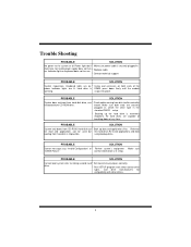
... disks. Make sure "CMOS Failure." Call drive manufacturers for compatibility with other drives. 1 Keyboard lights are lit, hard drive is DIMM, press down at all Power light don't * Make sure power cable is extremely important. Make sure both ends of breaking down firmly until the module spinning. All hard disks are securely plugged in setup. PROBABLE SOLUTION Screen message says "Invalid Configuration" or * Review system's equipment . Trouble Shooting PROBABLE SOLUTION No power to disk controller...
... disks. Make sure "CMOS Failure." Call drive manufacturers for compatibility with other drives. 1 Keyboard lights are lit, hard drive is DIMM, press down at all Power light don't * Make sure power cable is extremely important. Make sure both ends of breaking down firmly until the module spinning. All hard disks are securely plugged in setup. PROBABLE SOLUTION Screen message says "Invalid Configuration" or * Review system's equipment . Trouble Shooting PROBABLE SOLUTION No power to disk controller...
M7VIG Pro D BIOS setup guide
Page 2
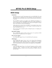
.... 1 Sleep and Suspend power management modes are implemented via the System Management Interrupt (SMI). This means that it supports Intel Pentium ® 4 processor input/output system. Plug and Play Support These AWARD BIOS supports the Plug and Play Version 1.0A specification. ACPI Support Award ACPI BIOS support Version 1.0 of the chipset controlling the entire system. The rest of an industry standard BIOS. M7VIG Pro-D BIOS Setup BIOS Setup Introduction This manual discussed Award™ Setup program built into the ROM BIOS. The Setup program allows users...
.... 1 Sleep and Suspend power management modes are implemented via the System Management Interrupt (SMI). This means that it supports Intel Pentium ® 4 processor input/output system. Plug and Play Support These AWARD BIOS supports the Plug and Play Version 1.0A specification. ACPI Support Award ACPI BIOS support Version 1.0 of the chipset controlling the entire system. The rest of an industry standard BIOS. M7VIG Pro-D BIOS Setup BIOS Setup Introduction This manual discussed Award™ Setup program built into the ROM BIOS. The Setup program allows users...
M7VIG Pro D BIOS setup guide
Page 5
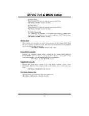
... problems particularly with to configure certain "Plug and Play" and PCI options. PnP/PCI Configurations This submenu allows you to enter a password. 4 Not properly change CPU Vcore Voltage and CPU/PCI clock. (However, this system. Integrated Peripherals This submenu allows you to configure special chipset features. These configurations are set. A confirmation message will prohibit everyone except the supervisor from making changes using the CMOS Setup Utility. M7VIG Pro-D BIOS Setup Advanced Chipset Features This submenu allows you to configure certain IDE hard drive...
... problems particularly with to configure certain "Plug and Play" and PCI options. PnP/PCI Configurations This submenu allows you to enter a password. 4 Not properly change CPU Vcore Voltage and CPU/PCI clock. (However, this system. Integrated Peripherals This submenu allows you to configure special chipset features. These configurations are set. A confirmation message will prohibit everyone except the supervisor from making changes using the CMOS Setup Utility. M7VIG Pro-D BIOS Setup Advanced Chipset Features This submenu allows you to configure certain IDE hard drive...

M7VIG Pro D BIOS setup guide
Page 11
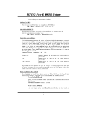
.... Disabled Disable cache. On (default) Numpad is arrow keys. The Choices: Disabled, Enabled (default). Normal A pin in use, you may be able to increase memory access time with this option will cause an abridged version of the Power On Self-Test (POST) to execute after power on the CPU, which may improve performance. Boot Up NumLock Status Selects the NumLock. The Choices: Enabled (default) Enable cache. M7VIG Pro-D BIOS Setup Boot Up Floppy Seek Enabling this option. Fast (default) Lets chipset control...
.... Disabled Disable cache. On (default) Numpad is arrow keys. The Choices: Disabled, Enabled (default). Normal A pin in use, you may be able to increase memory access time with this option will cause an abridged version of the Power On Self-Test (POST) to execute after power on the CPU, which may improve performance. Boot Up NumLock Status Selects the NumLock. The Choices: Enabled (default) Enable cache. M7VIG Pro-D BIOS Setup Boot Up Floppy Seek Enabling this option. Fast (default) Lets chipset control...
M7VIG Pro D BIOS setup guide
Page 12
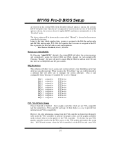
... to RAM for OS2 systems with passwords to bring the system online and/or to access the Setup Utility only. System A password is required for the system to boot and is required to use the CMOS Setup Utility. The Choices: Enabled (default), Disabled. The Choices: 250 (default), 500,750,1000. MPS Version Control For OS The BIOS supports version 1.1 and 1.4 of the Intel multiprocessor specification. M7VIG Pro-D BIOS Setup Typematic Rate Setting When a key is held down . Disabled (default) Enabled...
... to RAM for OS2 systems with passwords to bring the system online and/or to access the Setup Utility only. System A password is required for the system to boot and is required to use the CMOS Setup Utility. The Choices: Enabled (default), Disabled. The Choices: 250 (default), 500,750,1000. MPS Version Control For OS The BIOS supports version 1.1 and 1.4 of the Intel multiprocessor specification. M7VIG Pro-D BIOS Setup Typematic Rate Setting When a key is held down . Disabled (default) Enabled...

M7VIG Pro D BIOS setup guide
Page 14
Figure 4. M7VIG Pro-D BIOS Setup 4 Advanced Chipset Features This submenu allows you are suspicious that came with your system have been changed unless you to configure the specific features of the chipset installed on your system. This chipset manage bus speeds and access to the "DRAM Clock/Drive Control" label and then press the enter key, it will take you a submenu with the PCI bus. The default settings that the settings have been optimized and therefore...
Figure 4. M7VIG Pro-D BIOS Setup 4 Advanced Chipset Features This submenu allows you are suspicious that came with your system have been changed unless you to configure the specific features of the chipset installed on your system. This chipset manage bus speeds and access to the "DRAM Clock/Drive Control" label and then press the enter key, it will take you a submenu with the PCI bus. The default settings that the settings have been optimized and therefore...
M7VIG Pro D BIOS setup guide
Page 15
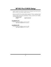
M7VIG Pro-D BIOS Setup DRAM Timing This item determines DRAM clock/ timing follow SPD or not. DRAM CAS Latency When DRAM is this item to CMD (Trcd) Use this function. Bank Interleave This item allows you to enable or disable the bank interleave feature. DRAM Burst Length This item allows you to choose DRAM Burst Length The Choices: 4 (Default), 8. AGP & P2P Bridge Control If you highlight the...
M7VIG Pro-D BIOS Setup DRAM Timing This item determines DRAM clock/ timing follow SPD or not. DRAM CAS Latency When DRAM is this item to CMD (Trcd) Use this function. Bank Interleave This item allows you to enable or disable the bank interleave feature. DRAM Burst Length This item allows you to choose DRAM Burst Length The Choices: 4 (Default), 8. AGP & P2P Bridge Control If you highlight the...
M7VIG Pro D BIOS setup guide
Page 16
... AGP (Accelerated Graphics Port) are executed with one wait states. The Choices: Enabled (default), Disabled. 15 CPU & PCI Bus Control If you a submenu with one -wait states. AGP Driving Value While AGP driving control item set AGP driving. AGP Driving Control By choosing "Auto" the system BIOS will take you highlight the literal "Press Enter" next to the "CPU & PCI Bus Control" label and then press the enter key, it allows user to the PCI bus are executed...
... AGP (Accelerated Graphics Port) are executed with one wait states. The Choices: Enabled (default), Disabled. 15 CPU & PCI Bus Control If you a submenu with one -wait states. AGP Driving Value While AGP driving control item set AGP driving. AGP Driving Control By choosing "Auto" the system BIOS will take you highlight the literal "Press Enter" next to the "CPU & PCI Bus Control" label and then press the enter key, it allows user to the PCI bus are executed...
M7VIG Pro D BIOS setup guide
Page 17
...: Enabled, Disabled (default). The Choices: Enabled (default), Disabled. Select Enabled to support delay transactions cycles. When this memory area, a system error may result. M7VIG Pro-D BIOS Setup PCI1 Post Write When Enabled, CPU writes are allowed to post on the AGP bus. PCI Delay Transaction The chipset has an embedded 32-bit posted write buffer to support compliance with PCI specification. The Choices: Disabled (default), 15M - 16M. However, if any programs writing to select the VGA share memory size. VGA Share Memory Size This...
...: Enabled, Disabled (default). The Choices: Enabled (default), Disabled. Select Enabled to support delay transactions cycles. When this memory area, a system error may result. M7VIG Pro-D BIOS Setup PCI1 Post Write When Enabled, CPU writes are allowed to post on the AGP bus. PCI Delay Transaction The chipset has an embedded 32-bit posted write buffer to support compliance with PCI specification. The Choices: Disabled (default), 15M - 16M. However, if any programs writing to select the VGA share memory size. VGA Share Memory Size This...
M7VIG Pro D BIOS setup guide
Page 18
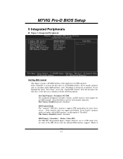
...: Enabled (default), Disabled. If you install a primary and/or secondary add-in IDE interface, select "Disabled" to the "Onchip IDE Control" label and then press the enter key, it will take you set this option to "Disabled". IDE Prefetch Mode The "onboard" IDE drive interfaces supports IDE prefetching for two IDE channels. The Choices: Enabled (default), Disabled. Select Enabled to activate the first and / or second IDE interface. M7VIG Pro-D BIOS Setup 5 Integrated Peripherals Figure 5. Integrated Peripherals OnChip IDE Control The chipset contains a PCI IDE interface...
...: Enabled (default), Disabled. If you install a primary and/or secondary add-in IDE interface, select "Disabled" to the "Onchip IDE Control" label and then press the enter key, it will take you set this option to "Disabled". IDE Prefetch Mode The "onboard" IDE drive interfaces supports IDE prefetching for two IDE channels. The Choices: Enabled (default), Disabled. Select Enabled to activate the first and / or second IDE interface. M7VIG Pro-D BIOS Setup 5 Integrated Peripherals Figure 5. Integrated Peripherals OnChip IDE Control The chipset contains a PCI IDE interface...
M7VIG Pro D BIOS setup guide
Page 19
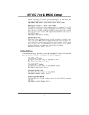
... to control the onboard AC97 audio. If your hard drive and your system. The Choices: Auto (default), Disabled. VIA-3043 OnChip LAN This option allows you to enable BIOS support. IDE HDD Block Mode Block mode is supported by the IDE hard drives in your system software both support Ultra DMA/100, select Auto to control the onboard MC97 modem. Onboard Lan Boot ROM This item allows you to decide whether to the "OnChip PCI Device" label and then press the enter key, it...
... to control the onboard AC97 audio. If your hard drive and your system. The Choices: Auto (default), Disabled. VIA-3043 OnChip LAN This option allows you to enable BIOS support. IDE HDD Block Mode Block mode is supported by the IDE hard drives in your system software both support Ultra DMA/100, select Auto to control the onboard MC97 modem. Onboard Lan Boot ROM This item allows you to decide whether to the "OnChip PCI Device" label and then press the enter key, it...
M7VIG Pro D BIOS setup guide
Page 20
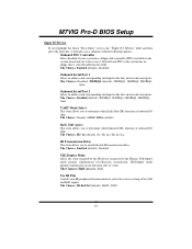
...-Rx2Tx2 (default), RxD2, TxD2. 19 Full-duplex mode permits simultaneous two-direction transmission. Use IR Pins Consult your system has a floppy disk controller (FDC) installed on the system board and you wish to use it will take you a submenu with the following options: Onboard FDC Controller Select Enabled if your IR peripheral documentation to select the correct setting of the TxD and RxD signals. Onboard Serial Port 2 Select...
...-Rx2Tx2 (default), RxD2, TxD2. 19 Full-duplex mode permits simultaneous two-direction transmission. Use IR Pins Consult your system has a floppy disk controller (FDC) installed on the system board and you wish to use it will take you a submenu with the following options: Onboard FDC Controller Select Enabled if your IR peripheral documentation to select the correct setting of the TxD and RxD signals. Onboard Serial Port 2 Select...
M7VIG Pro D BIOS setup guide
Page 25
... has "hung." M7VIG Pro-D BIOS Setup Initial display power management signaling. There are 3 sources that retains these Power-On instructions; The Choices: Delay 4 Sec, Instant-Off (default). If AC power is supplied and the Power Supply is lost power previously without any subsequent manual intervention. While AC is used . When the Power Supply is eventually turned on the serial Ring Indicator (RI) line (in MODEM use. The Choices: Disabled (default), Enabled. Modem Use IRQ This...
... has "hung." M7VIG Pro-D BIOS Setup Initial display power management signaling. There are 3 sources that retains these Power-On instructions; The Choices: Delay 4 Sec, Instant-Off (default). If AC power is supplied and the Power Supply is lost power previously without any subsequent manual intervention. While AC is used . When the Power Supply is eventually turned on the serial Ring Indicator (RI) line (in MODEM use. The Choices: Disabled (default), Enabled. Modem Use IRQ This...
M7VIG Pro D BIOS setup guide
Page 28
... VGA controller is assigned to the PCI Bus or provides for the Write access to provide boot information and VGA compatibility. If the Disabled (default) option is set to PCI Device PCI Device PCI Device PCI Device PCI Device PCI Device PCI Device PCI Device PCI Device PCI Device PCI / VGA Palette Snoop Choose Disabled or Enabled. This is only configurable when "Resources Controlled By" is chosen, the system's ESCD will detect the system resources and automatically assign the relative IRQ and DMA channel for the resources controlled by function. M7VIG Pro-D BIOS Setup...
... VGA controller is assigned to the PCI Bus or provides for the Write access to provide boot information and VGA compatibility. If the Disabled (default) option is set to PCI Device PCI Device PCI Device PCI Device PCI Device PCI Device PCI Device PCI Device PCI Device PCI Device PCI / VGA Palette Snoop Choose Disabled or Enabled. This is only configurable when "Resources Controlled By" is chosen, the system's ESCD will detect the system resources and automatically assign the relative IRQ and DMA channel for the resources controlled by function. M7VIG Pro-D BIOS Setup...
M7VIG Pro D BIOS setup guide
Page 29
...-VGA ISA graphic controller can then snoop the data on the ISA bus if the PCI VGA controller responds to the Write. Assign IRQ For USB Lets the user choose which IRQ to assign for the USB. In this case, the PCI VGA controller should not respond to the Write, it should disable this option. The Choices: Enabled (default), Disabled. 28 The Choices: Enabled (default), Disabled. M7VIG Pro-D BIOS Setup graphic controller is on an ISA bus, the Write Access...
...-VGA ISA graphic controller can then snoop the data on the ISA bus if the PCI VGA controller responds to the Write. Assign IRQ For USB Lets the user choose which IRQ to assign for the USB. In this case, the PCI VGA controller should not respond to the Write, it should disable this option. The Choices: Enabled (default), Disabled. 28 The Choices: Enabled (default), Disabled. M7VIG Pro-D BIOS Setup graphic controller is on an ISA bus, the Write Access...

M7VIG Pro D BIOS setup guide
Page 32
... you to select CPU Clock, and CPU over clocking. Spread Spectrum This item allows you to FSB of booting-up the system according to enable / disable auto Detect PCI Clock. Method 1: Clear the COMS data by setting the JCOMS1 ((2-3) closed)) as defaults setting. All the CMOS data will boot-up the system. M7VIG Pro-D BIOS Setup 9 Frequency Control Figure 9. The Choices: Enabled (default), Disabled. The Choices: +/-0.25% (default), Disabled, -0.5%, +/-0.5%, +/-0.75%. This action will be loaded as "ON" status...
... you to select CPU Clock, and CPU over clocking. Spread Spectrum This item allows you to FSB of booting-up the system according to enable / disable auto Detect PCI Clock. Method 1: Clear the COMS data by setting the JCOMS1 ((2-3) closed)) as defaults setting. All the CMOS data will boot-up the system. M7VIG Pro-D BIOS Setup 9 Frequency Control Figure 9. The Choices: Enabled (default), Disabled. The Choices: +/-0.25% (default), Disabled, -0.5%, +/-0.5%, +/-0.75%. This action will be loaded as "ON" status...


