

M7SXG user's manual
Page 7
...2.2 GHz CPU core speeds. The 33MHz 32 bit PCI 2.2 compliant. Chipset − SiS 650/645, SiS 961. − Winbond W83697HF. DRAM Memory − Supports 200MHz, 266MHz or 333MHz(only for SiS 645) DDR SDRAM devices. − Supports 128Mb, 256Mb ,512Mb and 1GB technologies. −...DIMMs with unbuffer (without ECC) PC2100/PC1600/PC2700(only for SiS 645). − The largest memory capacity is 2 GB for unbuffer DIMMs. Shadow RAM − Motherboard is equipped with a memory controller providing shadow RAM and support for high-end workstations system. Supports the Intel Pentium®...
...2.2 GHz CPU core speeds. The 33MHz 32 bit PCI 2.2 compliant. Chipset − SiS 650/645, SiS 961. − Winbond W83697HF. DRAM Memory − Supports 200MHz, 266MHz or 333MHz(only for SiS 645) DDR SDRAM devices. − Supports 128Mb, 256Mb ,512Mb and 1GB technologies. −...DIMMs with unbuffer (without ECC) PC2100/PC1600/PC2700(only for SiS 645). − The largest memory capacity is 2 GB for unbuffer DIMMs. Shadow RAM − Motherboard is equipped with a memory controller providing shadow RAM and support for high-end workstations system. Supports the Intel Pentium®...

M7SXG user's manual
Page 8
... Codec Onboard − AC-LINK protocol compliance. − Compliant with CD-ROM. − Supports high capacity hard disk drives. − Supports LBA mode. Flash Memory − Supports flash memory functionality. − Supports ESCD functionality. BUS Slots − One AGP slot (support AGP v2.0 compliant). − One CNR slot. − Three 32-bit...
... Codec Onboard − AC-LINK protocol compliance. − Compliant with CD-ROM. − Supports high capacity hard disk drives. − Supports LBA mode. Flash Memory − Supports flash memory functionality. − Supports ESCD functionality. BUS Slots − One AGP slot (support AGP v2.0 compliant). − One CNR slot. − Three 32-bit...

M7SXG user's manual
Page 11
Chapter 1 Motherboard Description 1.1.2 BIOS − Award BIOS. − Supports APM1.2. − Supports USB Function. − Supports ACPI. − BIOS Update. 1.1.3 Software Operating System − Offers the highest performance for MS-DOS, Windows NT, Windows 2000, Windows 95/98, Windows ME, Windows XP, Novell, SCO UNIX etc. 1.1.4 Accessories − HDD Cable. − FDD Cable. − Flash Memory Writer for BIOS Update. − JUSB1/JUSB2 Cable (Optional). − Rear I/O Panel for Micro ATX Case (Optional). − Fully Setup Driver CD. 1-6
Chapter 1 Motherboard Description 1.1.2 BIOS − Award BIOS. − Supports APM1.2. − Supports USB Function. − Supports ACPI. − BIOS Update. 1.1.3 Software Operating System − Offers the highest performance for MS-DOS, Windows NT, Windows 2000, Windows 95/98, Windows ME, Windows XP, Novell, SCO UNIX etc. 1.1.4 Accessories − HDD Cable. − FDD Cable. − Flash Memory Writer for BIOS Update. − JUSB1/JUSB2 Cable (Optional). − Rear I/O Panel for Micro ATX Case (Optional). − Fully Setup Driver CD. 1-6

M7SXG user's manual
Page 17
... Unbuffered DDR SDRAM (without ECC) PC1600/ PC2100/ PC2700 Type required. DRAM Type: 128MB/ 256MB/ 512MB/ 1GB DIMM Module (184 pin) Total Memory Size with unbuffer DIMMs (Only for reference) Total Memory DIMM 1 DIMM 2 Size (MB) 128 M 128 M ---- 256 M 256 M ---- 512 M 512 M ---- 1 G 256 M 384 M 1G 128 M 256 M ---128 M 128 M 640 M 1128 M 384 M 512...
... Unbuffered DDR SDRAM (without ECC) PC1600/ PC2100/ PC2700 Type required. DRAM Type: 128MB/ 256MB/ 512MB/ 1GB DIMM Module (184 pin) Total Memory Size with unbuffer DIMMs (Only for reference) Total Memory DIMM 1 DIMM 2 Size (MB) 128 M 128 M ---- 256 M 256 M ---- 512 M 512 M ---- 1 G 256 M 384 M 1G 128 M 256 M ---128 M 128 M 640 M 1128 M 384 M 512...

M7SXG user's manual
Page 18
Insert the DIMM memory modules into the socket at a 90-degree angle, then push down vertically so that it will fit into the slot in place. 1-13 The Mounting Holes and plastic tabs should fit over the edge and hold the DIMM memory modules in one direction. 2. Push the tabs out. Chapter 1 Motherboard Description 1.4.2 How to install a DIMM Module Single Sided DIMM Double Sided DIMM 1. The DIMM socket has a " Plastic Safety Tab" ,and the DIMM memory module has an Asymmetrical notch", so the DIMM memory module can only fit into the place. 3.
Insert the DIMM memory modules into the socket at a 90-degree angle, then push down vertically so that it will fit into the slot in place. 1-13 The Mounting Holes and plastic tabs should fit over the edge and hold the DIMM memory modules in one direction. 2. Push the tabs out. Chapter 1 Motherboard Description 1.4.2 How to install a DIMM Module Single Sided DIMM Double Sided DIMM 1. The DIMM socket has a " Plastic Safety Tab" ,and the DIMM memory module has an Asymmetrical notch", so the DIMM memory module can only fit into the place. 3.

M7SXG user's manual
Page 37
... through the process of an industry standard BIOS. ESCD (Extended System Configuration Data) write is a custom version of configuring your computer system's ROM (Read Only Memory) is supported. Sleep and Suspend power management modes are implemented via the System Management Interrupt (SMI).
... through the process of an industry standard BIOS. ESCD (Extended System Configuration Data) write is a custom version of configuring your computer system's ROM (Read Only Memory) is supported. Sleep and Suspend power management modes are implemented via the System Management Interrupt (SMI).
M7SXG user's manual
Page 41
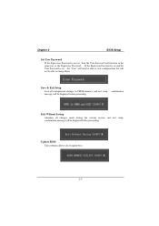
message will be displayed before proceeding. Update BIOS This submenu allows you to CMOS(memory) and exit setup. If the Supervisor Password is set and the User Password is not set , the "User" will only be able to change them. ...
message will be displayed before proceeding. Update BIOS This submenu allows you to CMOS(memory) and exit setup. If the Supervisor Password is set and the User Password is not set , the "User" will only be able to change them. ...

M7SXG user's manual
Page 44
Displays the amount of conventional memory detected during boot up . Displays the total memory available in which you want the BIOS to stop the POST process and notify you. Displays the amount of extended memory detected during boot up . Chapter 2 BIOS Setup Item Halt On Base Memory Extended Memory Total Memory Options All Errors No Errors All, but Keyboard All, but Diskette All, but Disk/ Key N/A N/A N/A Description Select the situation in the system. 2-8
Displays the amount of conventional memory detected during boot up . Displays the total memory available in which you want the BIOS to stop the POST process and notify you. Displays the amount of extended memory detected during boot up . Chapter 2 BIOS Setup Item Halt On Base Memory Extended Memory Total Memory Options All Errors No Errors All, but Keyboard All, but Diskette All, but Disk/ Key N/A N/A N/A Description Select the situation in the system. 2-8

M7SXG user's manual
Page 45
.... If this option. Virus protection is used to the boot sector, BIOS will display a warning message on the CPU/chipset in use, you to increase memory access time with this function is enabled and an attempt is disabled. Advanced BIOS Setup Virus Warning This option allows you may be able to...
.... If this option. Virus protection is used to the boot sector, BIOS will display a warning message on the CPU/chipset in use, you to increase memory access time with this function is enabled and an attempt is disabled. Advanced BIOS Setup Virus Warning This option allows you may be able to...

M7SXG user's manual
Page 48
... the version supported by the operation system running on this computer. Report No FDD For WIN 95 Whether report no FDD for OS2 systems with memory exceeding 64MB. The Choices: No (default), Yes. OS Select For DRAM > 64MB A choice other than Non-OS2 is enabled. The Choices: Disabled (default), Enabled. 2-12...
... the version supported by the operation system running on this computer. Report No FDD For WIN 95 Whether report no FDD for OS2 systems with memory exceeding 64MB. The Choices: No (default), Yes. OS Select For DRAM > 64MB A choice other than Non-OS2 is enabled. The Choices: Disabled (default), Enabled. 2-12...

M7SXG user's manual
Page 49
... optimized and therefore should not be changed unless you are suspicious that came with your system. This chipset manages bus speeds and access to system memory resources, such as DRAM and external cache.
... optimized and therefore should not be changed unless you are suspicious that came with your system. This chipset manages bus speeds and access to system memory resources, such as DRAM and external cache.

M7SXG user's manual
Page 50
... documentation of the peripheral you are forwarded to the AGP without any translation. AGP Aperture Size Select the size of the PCI memory address range dedicated for ISA adapter ROM. Host cycles that hit the aperture range are installing for more information. Prefetch Caching This... can reserve an area of CAS latency depends on the DRAM timing. When this area is installed, the number of clock cycles of system memory for graphics memory address space. The Choices: Enabled (default), Disabled. 2-14 The Choices: Auto (default), 2T, 2.5T. The Choices: Disabled (default), Enabled. ...
... documentation of the peripheral you are forwarded to the AGP without any translation. AGP Aperture Size Select the size of the PCI memory address range dedicated for ISA adapter ROM. Host cycles that hit the aperture range are installing for more information. Prefetch Caching This... can reserve an area of CAS latency depends on the DRAM timing. When this area is installed, the number of clock cycles of system memory for graphics memory address space. The Choices: Enabled (default), Disabled. 2-14 The Choices: Auto (default), 2T, 2.5T. The Choices: Disabled (default), Enabled. ...

M7SXG user's manual
Page 52
..." next to control the onboard LAN. The Choices: Enabled (default), Disabled. The Choices: Disabled (default), Enabled. SiS-900 MAC Address Input System Share Memory Size (Only for M7SXH) This item allows you a submenu with the following options: 2-16 IDE Burst Mode This item allows you to control the onboard... AUDIO This option allows you to the "Onboard Super IO Device" label and then press the enter key, it will take you select System Share Memory Size The Choices: 32 MB (default), 4MB, 8MB, 16MB, 64MB. As well, your system. The Choices: Enabled (default), Disabled. If your hard...
..." next to control the onboard LAN. The Choices: Enabled (default), Disabled. The Choices: Disabled (default), Enabled. SiS-900 MAC Address Input System Share Memory Size (Only for M7SXH) This item allows you a submenu with the following options: 2-16 IDE Burst Mode This item allows you to control the onboard... AUDIO This option allows you to the "Onboard Super IO Device" label and then press the enter key, it will take you select System Share Memory Size The Choices: 32 MB (default), 4MB, 8MB, 16MB, 64MB. As well, your system. The Choices: Enabled (default), Disabled. If your hard...

M7SXG user's manual
Page 60
... new configuration varies from conflict. If the Enabled option is chosen, the system is forced to update ESCDs and then is automatically set to the memory locations. The system needs to record and update ESCD to the "Disabled" mode. The Choices: Disabled (default), Enabled. 2-24 Chapter 2 BIOS Setup 2.7 PnP/PCI Configurations...
... new configuration varies from conflict. If the Enabled option is chosen, the system is forced to update ESCDs and then is automatically set to the memory locations. The system needs to record and update ESCD to the "Disabled" mode. The Choices: Disabled (default), Enabled. 2-24 Chapter 2 BIOS Setup 2.7 PnP/PCI Configurations...
M7SXG user's manual
Page 67
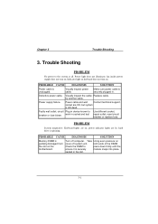
... unit. Chapter 3 Trouble Shooting 3. Power light does not illuminate, fan inside power supply does not turn on . Visually inspect the cable; PROBABLE CAUSE DIAGNOSIS SOLUTION Memory DIMM is unplugged. Defective power cable. Replace cable. Faulty wall outlet; work in the slot. 3-1 Take Using even pressure on the motherboard. both ends of...
... unit. Chapter 3 Trouble Shooting 3. Power light does not illuminate, fan inside power supply does not turn on . Visually inspect the cable; PROBABLE CAUSE DIAGNOSIS SOLUTION Memory DIMM is unplugged. Defective power cable. Replace cable. Faulty wall outlet; work in the slot. 3-1 Take Using even pressure on the motherboard. both ends of...

M7SXG user's manual
Page 70
Keyboard failure. Check keys again, if no improvement replace keyboard. 3-4 Reinstall memory, make sure that all memory modules are installed in correct sockets. DIAGNOSIS SOLUTION Disable screen saver. PROBLEM PROBABLE CAUSE Keyboard is enabled. DIAGNOSIS SOLUTION Reconnect keyboard. PROBLEM PROBABLE CAUSE Memory problem. Computer virus. PROBABLE CAUSE Screen saver is disconnected. Chapter 3 Trouble Shooting No screen. Use anti-virus programs to detect and clean viruses. DIAGNOSIS SOLUTION Reboot computer. PROBLEM Screen goes blank periodically.
Keyboard failure. Check keys again, if no improvement replace keyboard. 3-4 Reinstall memory, make sure that all memory modules are installed in correct sockets. DIAGNOSIS SOLUTION Disable screen saver. PROBLEM PROBABLE CAUSE Keyboard is enabled. DIAGNOSIS SOLUTION Reconnect keyboard. PROBLEM PROBABLE CAUSE Memory problem. Computer virus. PROBABLE CAUSE Screen saver is disconnected. Chapter 3 Trouble Shooting No screen. Use anti-virus programs to detect and clean viruses. DIAGNOSIS SOLUTION Reboot computer. PROBLEM Screen goes blank periodically.

M7SXG compatibility test report
Page 2
CONTENTS PRODUCT INFORMATION 4 Motherboard General Information 4 Chipset Details...4 BIOS Details ...4 CPU Supports...4 Memory Supports 4 On-board Features and Devices 4 Mechanical...5 DESIGN REVIEW 7 Mainboard Voltage Measurement 7 Bus Clock ...7 REQUIRED BIOS DEFAULT SETTINGS 8 BIOS FEATURES SETUP 8 CHIPSET FEATURES SETUP 8 POWER ...
CONTENTS PRODUCT INFORMATION 4 Motherboard General Information 4 Chipset Details...4 BIOS Details ...4 CPU Supports...4 Memory Supports 4 On-board Features and Devices 4 Mechanical...5 DESIGN REVIEW 7 Mainboard Voltage Measurement 7 Bus Clock ...7 REQUIRED BIOS DEFAULT SETTINGS 8 BIOS FEATURES SETUP 8 CHIPSET FEATURES SETUP 8 POWER ...

M7SXG compatibility test report
Page 3
...-ROM...34 Camera Device...35 DVD-ROM ...35 Display Card...35 FDD ...36 HDD ...37 Joystick ...38 Keyboard ...38 LAN Card...38 LAN HUB...39 Memory ...39 Modem Card...40 Mouse...40 Monitor ...40 Power Supply ...41 Printer...42 Scanner ...42 SCSI Card ...42 Sound Card ...43 USB HUB ...43 ZIP...
...-ROM...34 Camera Device...35 DVD-ROM ...35 Display Card...35 FDD ...36 HDD ...37 Joystick ...38 Keyboard ...38 LAN Card...38 LAN HUB...39 Memory ...39 Modem Card...40 Mouse...40 Monitor ...40 Power Supply ...41 Printer...42 Scanner ...42 SCSI Card ...42 Sound Card ...43 USB HUB ...43 ZIP...

M7SXG compatibility test report
Page 4
... †2 ;3 †4 †5 No of ISA Full Length Slots AMR Slot Support CNR Slot Support ACR Slot Support Number of Memory Supported DDR 1024 (MB) ; PRODUCT INFORMATION Vendor Motherboard General Information Biostar Model Number Version Number Platform System Chipset Vendor North Bridge Revision South Bridge Revision Super I/O Chip Vendor Super I/O Revision Number...
... †2 ;3 †4 †5 No of ISA Full Length Slots AMR Slot Support CNR Slot Support ACR Slot Support Number of Memory Supported DDR 1024 (MB) ; PRODUCT INFORMATION Vendor Motherboard General Information Biostar Model Number Version Number Platform System Chipset Vendor North Bridge Revision South Bridge Revision Super I/O Chip Vendor Super I/O Revision Number...

M7SXG compatibility test report
Page 8
... DRAM Control Press Enter Pass System Performance Normal Mode Pass CAS Latency Setting Auto Pass DRAM Addr/Cmd Rate Auto Pass Prefetch Caching Enabled Pass Memory Hole at 15M-16M Disabled Pass AGP Aperture Size 64MB Pass Graphic Window WR Combin Enabled Pass POWER MANAGEMENT SETUP ACPI Function Enabled Pass ACPI...
... DRAM Control Press Enter Pass System Performance Normal Mode Pass CAS Latency Setting Auto Pass DRAM Addr/Cmd Rate Auto Pass Prefetch Caching Enabled Pass Memory Hole at 15M-16M Disabled Pass AGP Aperture Size 64MB Pass Graphic Window WR Combin Enabled Pass POWER MANAGEMENT SETUP ACPI Function Enabled Pass ACPI...


