
M7SXG user's manual
Page 3
Contents Introduction 1-1 1. Motherboard Description 1-2 1.1 Features 1-2 1.1.1 Hardware...1-2 1.1.2 BIOS ...1-6 1.1.3 Software...1-6 1.1.4 Accessories ...1-6 1.2 Motherboard Installation 1-7 1.2.1 System Block Diagram 1-7 1.2.2 Layout of Motherboard 1-8 1.2.3 Quick Reference 1-8 1.2.3 Quick Reference 1-9 1.3 CPU Installation 1-10 1.3.1 CPU Installation Procedure: Socket 478 1-10 1.3.2 CPU Fan ...
Contents Introduction 1-1 1. Motherboard Description 1-2 1.1 Features 1-2 1.1.1 Hardware...1-2 1.1.2 BIOS ...1-6 1.1.3 Software...1-6 1.1.4 Accessories ...1-6 1.2 Motherboard Installation 1-7 1.2.1 System Block Diagram 1-7 1.2.2 Layout of Motherboard 1-8 1.2.3 Quick Reference 1-8 1.2.3 Quick Reference 1-9 1.3 CPU Installation 1-10 1.3.1 CPU Installation Procedure: Socket 478 1-10 1.3.2 CPU Fan ...
M7SXG user's manual
Page 5
Trouble Shooting 3-1 iii BIOS Setup 2-1 2.1 Main Menu 2-3 2.2 Standard CMOS Features 2-6 2.3 Advanced BIOS Features 2-9 2.4 Advanced Chipset Features 2-13 2.5 Integrated Peripherals 2-15 2.6 Power Management Setup 2-21 2.7 PnP/PCI Configurations 2-24 2.8 PC Health Status 2-27 2.9 Frequency Control 2-29 3. Contents 1.7.7.4 Telephony Audio Header: JTAD1 1-31 2.
Trouble Shooting 3-1 iii BIOS Setup 2-1 2.1 Main Menu 2-3 2.2 Standard CMOS Features 2-6 2.3 Advanced BIOS Features 2-9 2.4 Advanced Chipset Features 2-13 2.5 Integrated Peripherals 2-15 2.6 Power Management Setup 2-21 2.7 PnP/PCI Configurations 2-24 2.8 PC Health Status 2-27 2.9 Frequency Control 2-29 3. Contents 1.7.7.4 Telephony Audio Header: JTAD1 1-31 2.

M7SXG user's manual
Page 7
Motherboard Description 1.1 Features 1.1.1 Hardware CPU − − Provides Socket-478. Supports the Intel Pentium® 4 processor providing the new generation power for ROM BIOS. 1-2 Supports up to 2.2 GHz CPU core speeds. The 33MHz 32 bit PCI 2.2 compliant. Chipset − SiS 650/645, SiS 961. − Winbond W83697HF. DRAM Memory &#...
Motherboard Description 1.1 Features 1.1.1 Hardware CPU − − Provides Socket-478. Supports the Intel Pentium® 4 processor providing the new generation power for ROM BIOS. 1-2 Supports up to 2.2 GHz CPU core speeds. The 33MHz 32 bit PCI 2.2 compliant. Chipset − SiS 650/645, SiS 961. − Winbond W83697HF. DRAM Memory &#...

M7SXG user's manual
Page 8
... AGP slot (support AGP v2.0 compliant). − One CNR slot. − Three 32-bit PCI bus slots. Chapter 1 Motherboard Description Green Functionality − Supports Award BIOS ™ power management functionality. − Has a power down timer from power saving sleep mode with any keyboard or mouse activity.
... AGP slot (support AGP v2.0 compliant). − One CNR slot. − Three 32-bit PCI bus slots. Chapter 1 Motherboard Description Green Functionality − Supports Award BIOS ™ power management functionality. − Has a power down timer from power saving sleep mode with any keyboard or mouse activity.

M7SXG user's manual
Page 10
Dimensions (Micro ATX form-factor) − 24.5cm x 24.5cm (WxL) 1-5 Chapter 1 Motherboard Description BIOS Hardware Monitor Function − Monitors CPU Fan Speed. − Monitors System Fan Speed. − Monitors System Voltage.
Dimensions (Micro ATX form-factor) − 24.5cm x 24.5cm (WxL) 1-5 Chapter 1 Motherboard Description BIOS Hardware Monitor Function − Monitors CPU Fan Speed. − Monitors System Fan Speed. − Monitors System Voltage.

M7SXG user's manual
Page 11
Chapter 1 Motherboard Description 1.1.2 BIOS − Award BIOS. − Supports APM1.2. − Supports USB Function. − Supports ACPI. − BIOS Update. 1.1.3 Software Operating System − Offers the highest performance for MS-DOS, Windows NT, Windows 2000, Windows 95/98, Windows ME, Windows XP, Novell, SCO UNIX etc. 1.1.4 Accessories − HDD Cable. − FDD Cable. − Flash Memory Writer for BIOS Update. − JUSB1/JUSB2 Cable (Optional). − Rear I/O Panel for Micro ATX Case (Optional). − Fully Setup Driver CD. 1-6
Chapter 1 Motherboard Description 1.1.2 BIOS − Award BIOS. − Supports APM1.2. − Supports USB Function. − Supports ACPI. − BIOS Update. 1.1.3 Software Operating System − Offers the highest performance for MS-DOS, Windows NT, Windows 2000, Windows 95/98, Windows ME, Windows XP, Novell, SCO UNIX etc. 1.1.4 Accessories − HDD Cable. − FDD Cable. − Flash Memory Writer for BIOS Update. − JUSB1/JUSB2 Cable (Optional). − Rear I/O Panel for Micro ATX Case (Optional). − Fully Setup Driver CD. 1-6
M7SXG user's manual
Page 13
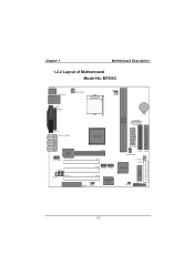
M7SXG JKBMS1 JATXPWR2 Socket 478 JCFAN1 JCOM1 JPRNT1 BAT1 JAUXPWR1 DDR 1 DDR 2 SECONDARY IDE CONN. JVGA1 SP-OUT JAUD_GAME1 GAME Port LINE-IN MIC-IN 2 1 JAUDIO1 LAN CHIP JCDIN1 11 1 JCDIN2 JTAD1 AGP1 PCI1 2 2 1 1 PCI2 JUSB2 JUSB1 JATXPWR1 1 DDR1 DDR2 JDIMMPWR1 IDE2 IDE1 1 JSFAN1 FDD1 SiS 961 BIOS FLOPPY DISK CONN. Chapter 1 Motherboard Description 1.2.2 Layout of Motherboard Model No. PRIMARY IDE CONN. PCI3 1 CNR1 JWOL1 Winbond I/O 1 JPANEL1 JCMOS1 2 1 1-8
M7SXG JKBMS1 JATXPWR2 Socket 478 JCFAN1 JCOM1 JPRNT1 BAT1 JAUXPWR1 DDR 1 DDR 2 SECONDARY IDE CONN. JVGA1 SP-OUT JAUD_GAME1 GAME Port LINE-IN MIC-IN 2 1 JAUDIO1 LAN CHIP JCDIN1 11 1 JCDIN2 JTAD1 AGP1 PCI1 2 2 1 1 PCI2 JUSB2 JUSB1 JATXPWR1 1 DDR1 DDR2 JDIMMPWR1 IDE2 IDE1 1 JSFAN1 FDD1 SiS 961 BIOS FLOPPY DISK CONN. Chapter 1 Motherboard Description 1.2.2 Layout of Motherboard Model No. PRIMARY IDE CONN. PCI3 1 CNR1 JWOL1 Winbond I/O 1 JPANEL1 JCMOS1 2 1 1-8

M7SXG user's manual
Page 14
M NO A. Back Panel I /O J T SiS 961 K DDR 1 DDR 2 S R Q L BIOS SECONDARY IDE CONN. PCI BUS Slots (PCI1-3) D. CNR Slot (CNR1) H. Clear CMOS (JCMOS1) L. System FAN Header (*JSFAN1) O. ATX 12V Power Connector (JATXPWR2) NOTE: The " * "mark ...
M NO A. Back Panel I /O J T SiS 961 K DDR 1 DDR 2 S R Q L BIOS SECONDARY IDE CONN. PCI BUS Slots (PCI1-3) D. CNR Slot (CNR1) H. Clear CMOS (JCMOS1) L. System FAN Header (*JSFAN1) O. ATX 12V Power Connector (JATXPWR2) NOTE: The " * "mark ...
M7SXG user's manual
Page 16
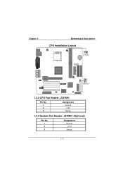
LAN CHIP 1 SiS 961 JSFAN1 BIOS FLOPPY DISK CONN. PRIMARY IDE CONN. Chapter 1 Motherboard Description CPU Installation Layout Socket 478 1 JCFAN1 DDR 1 DDR 2 SECONDARY IDE CONN. Winbond I/O 1.3.2 CPU Fan Header: JCFAN1 Pin No. 1 2 3 Assignment Ground +12V Sense 1.3.3 System Fan Header: JSFAN1 (Optional) Pin No. 1 2 3 Assignment Ground +12V Sense 1-11
LAN CHIP 1 SiS 961 JSFAN1 BIOS FLOPPY DISK CONN. PRIMARY IDE CONN. Chapter 1 Motherboard Description CPU Installation Layout Socket 478 1 JCFAN1 DDR 1 DDR 2 SECONDARY IDE CONN. Winbond I/O 1.3.2 CPU Fan Header: JCFAN1 Pin No. 1 2 3 Assignment Ground +12V Sense 1.3.3 System Fan Header: JSFAN1 (Optional) Pin No. 1 2 3 Assignment Ground +12V Sense 1-11

M7SXG user's manual
Page 19
Chapter 1 Motherboard Description 1.5 Slots The slots in this motherboard are not part of adding or enhancing the motherboard's features and capabilities. AGP Slot LAN CHIP PCI Slot CNR Slot SiS 961 Winbond I/O 1-14 Expansion slots are a means of the basic system. BIOS FLOPPY DISK CONN. With these efficient facilities, you can increase the motherboard's capabilities by adding hardware that performs tasks that are designed to hold expansion cards and connect them to the system bus. Socket 478 DDR 1 DDR 2 SECONDARY IDE CONN. PRIMARY IDE CONN.
Chapter 1 Motherboard Description 1.5 Slots The slots in this motherboard are not part of adding or enhancing the motherboard's features and capabilities. AGP Slot LAN CHIP PCI Slot CNR Slot SiS 961 Winbond I/O 1-14 Expansion slots are a means of the basic system. BIOS FLOPPY DISK CONN. With these efficient facilities, you can increase the motherboard's capabilities by adding hardware that performs tasks that are designed to hold expansion cards and connect them to the system bus. Socket 478 DDR 1 DDR 2 SECONDARY IDE CONN. PRIMARY IDE CONN.

M7SXG user's manual
Page 21
... select different system options. PRIMARY IDE CONN. Socket 478 JATXPWR2 JATXPWR1 JAUXPWR1 DDR 1 DDR 2 SECONDARY IDE CONN. LAN CHIP SiS 961 Winbond I/O JWOL1 JUSB2 JUSB1JCMOS1 BIOS FLOPPY DISK CONN. Noticeably, a jumper has two or more pins that can be covered by a plastic jumper cap, allowing you lots of capabilities such as...
... select different system options. PRIMARY IDE CONN. Socket 478 JATXPWR2 JATXPWR1 JAUXPWR1 DDR 1 DDR 2 SECONDARY IDE CONN. LAN CHIP SiS 961 Winbond I/O JWOL1 JUSB2 JUSB1JCMOS1 BIOS FLOPPY DISK CONN. Noticeably, a jumper has two or more pins that can be covered by a plastic jumper cap, allowing you lots of capabilities such as...
M7SXG user's manual
Page 23
... down the monitor and hard drives until the system is invoked by powering down the monitor and the hard disk when not in the system BIOS and the APM driver must be enabled in use. IR (Infrared Connector) This connector is powered on. APM (Advanced Power Management) must be loaded. At...
... down the monitor and hard drives until the system is invoked by powering down the monitor and the hard disk when not in the system BIOS and the APM driver must be enabled in use. IR (Infrared Connector) This connector is powered on. APM (Advanced Power Management) must be loaded. At...
M7SXG user's manual
Page 25
... 360K, 720K, 1.2M, 1.44M and 2.88M floppy disk types. IDE1 can connect up to four hard disk drives, a CD-ROM, a 120MB Floppy (reserved for future BIOS) and other devices to IDE1 and IDE2. The second drive on IDE1 to slave mode. 1.6.7 Floppy Disk Connector: FDD1 The motherboard provides a standard floppy disk...
... 360K, 720K, 1.2M, 1.44M and 2.88M floppy disk types. IDE1 can connect up to four hard disk drives, a CD-ROM, a 120MB Floppy (reserved for future BIOS) and other devices to IDE1 and IDE2. The second drive on IDE1 to slave mode. 1.6.7 Floppy Disk Connector: FDD1 The motherboard provides a standard floppy disk...
M7SXG user's manual
Page 26
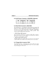
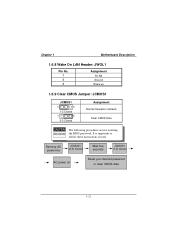
Chapter 1 Motherboard Description 1.6.8 Wake On LAN Header: JWOL1 Pin No. 1 2 3 Assignment 5V SB Ground Wake up 1.6.9 Clear CMOS Jumper: JCMOS1 JCMOS1 1 3 1-2 Closed 1 3 2-3 Closed Assignment Normal Operation (default) Clear CMOS Data The following procedures are for resetting the BIOS password. Remove AC power line JCMOS1 (2-3) closed Wait five seconds JCMOS1 (1-2) closed AC power on Reset your desired password or clear CMOS data 1-21 It is important to follow these instructions closely.
Chapter 1 Motherboard Description 1.6.8 Wake On LAN Header: JWOL1 Pin No. 1 2 3 Assignment 5V SB Ground Wake up 1.6.9 Clear CMOS Jumper: JCMOS1 JCMOS1 1 3 1-2 Closed 1 3 2-3 Closed Assignment Normal Operation (default) Clear CMOS Data The following procedures are for resetting the BIOS password. Remove AC power line JCMOS1 (2-3) closed Wait five seconds JCMOS1 (1-2) closed AC power on Reset your desired password or clear CMOS data 1-21 It is important to follow these instructions closely.
M7SXG user's manual
Page 35
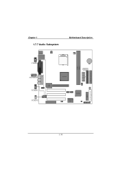
PRIMARY IDE CONN. 2 1 JAUDIO1 1 LAN CHIP JCDIN1 1 JCDIN2 SiS 961 Winbond I/O BIOS FLOPPY DISK CONN. 1-30 Chapter 1 1.7.7 Audio Subsystem Motherboard Description 1 JTAD1 Socket 478 DDR 1 DDR 2 SECONDARY IDE CONN.
PRIMARY IDE CONN. 2 1 JAUDIO1 1 LAN CHIP JCDIN1 1 JCDIN2 SiS 961 Winbond I/O BIOS FLOPPY DISK CONN. 1-30 Chapter 1 1.7.7 Audio Subsystem Motherboard Description 1 JTAD1 Socket 478 DDR 1 DDR 2 SECONDARY IDE CONN.

M7SXG user's manual
Page 37
... specification. Sleep and Suspend power management modes are implemented via the System Management Interrupt (SMI). Adding important has customized the Award BIOS™, but nonstandard, features such as virus and password protection as well as special support for standard devices such as disk drives... system's ROM (Read Only Memory) is supported. Power management features are supported. This special information is turned off. The Award BIOS™ installed in battery-backed RAM so that it retains the Setup information when the power is then stored in your system using...
... specification. Sleep and Suspend power management modes are implemented via the System Management Interrupt (SMI). Adding important has customized the Award BIOS™, but nonstandard, features such as virus and password protection as well as special support for standard devices such as disk drives... system's ROM (Read Only Memory) is supported. Power management features are supported. This special information is turned off. The Award BIOS™ installed in battery-backed RAM so that it retains the Setup information when the power is then stored in your system using...
M7SXG user's manual
Page 38
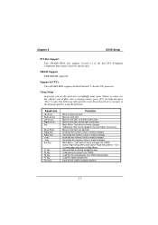
...the and keys to change entries, press for help on Setup navigation keys Load previous values from CMOS Load the fail-safe defaults from BIOS default table Load the optimized defaults Save all the CMOS changes and exit 2-2 Keystroke Up arrow Down arrow Left arrow Right arrow Esc Move... page and return to Main Menu General help and press to navigate in the Setup program by using the keyboard. Chapter 2 BIOS Setup PCI Bus Support This AWARD BIOS also supports Version 2.1 of the Intel PCI (Peripheral Component Interconnect) local bus specification. Quit and not save changes into CMOS...
...the and keys to change entries, press for help on Setup navigation keys Load previous values from CMOS Load the fail-safe defaults from BIOS default table Load the optimized defaults Save all the CMOS changes and exit 2-2 Keystroke Up arrow Down arrow Left arrow Right arrow Esc Move... page and return to Main Menu General help and press to navigate in the Setup program by using the keyboard. Chapter 2 BIOS Setup PCI Bus Support This AWARD BIOS also supports Version 2.1 of the Intel PCI (Peripheral Component Interconnect) local bus specification. Quit and not save changes into CMOS...
M7SXG user's manual
Page 39
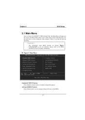
...The Main Menu allows you enter Award BIOS™ CMOS Setup Utility, the Main Menu will appear on the screen. The information about BIOS defaults on board, for update information. Advanced BIOS Features This submenu allows you to the BIOS installed on manual (Figure 1,2,3,4,5,6,7,8,9) is just... for reference, please refer to configure enhanced features of the BIOS. 2-3 Use the arrow keys ...
...The Main Menu allows you enter Award BIOS™ CMOS Setup Utility, the Main Menu will appear on the screen. The information about BIOS defaults on board, for update information. Advanced BIOS Features This submenu allows you to the BIOS installed on manual (Figure 1,2,3,4,5,6,7,8,9) is just... for reference, please refer to configure enhanced features of the BIOS. 2-3 Use the arrow keys ...
M7SXG user's manual
Page 40
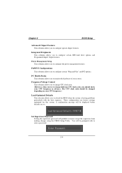
... Supervisor Password Setting the supervisor password will be displayed before defaults are factory settings optimized for this system. Chapter 2 BIOS Setup Advanced Chipset Features This submenu allows you to reload the BIOS when the system is having problems particularly with to configure certain IDE hard drive options and Programmed Input/ Output features...
... Supervisor Password Setting the supervisor password will be displayed before defaults are factory settings optimized for this system. Chapter 2 BIOS Setup Advanced Chipset Features This submenu allows you to reload the BIOS when the system is having problems particularly with to configure certain IDE hard drive options and Programmed Input/ Output features...
M7SXG user's manual
Page 41
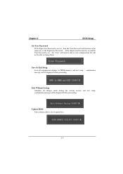
...message will not be able to change them. message will function in the same way as the Supervisor Password. Update BIOS This submenu allows you to update bios. 2-5 confirmation Exit Without Saving Abandon all configuration changes to CMOS(memory) and exit setup. Save & Exit Setup ...Save all changes made during the current session and exit setup. Chapter 2 BIOS Setup Set User Password If the Supervisor Password is...
...message will not be able to change them. message will function in the same way as the Supervisor Password. Update BIOS This submenu allows you to update bios. 2-5 confirmation Exit Without Saving Abandon all configuration changes to CMOS(memory) and exit setup. Save & Exit Setup ...Save all changes made during the current session and exit setup. Chapter 2 BIOS Setup Set User Password If the Supervisor Password is...

