

M7SXF user's manual
Page 7
...4 processor providing the new generation power for M7SXF) or up to 3 unbuffer DIMM DDR 266/200. The 66MHz AGP 2.0 compliant interface supports 1x, 2x and 4x data transfer mode. DRAM Memory − Supports 200MHz, 266MHz or 333MHz (only for M7SXF) DDR SDRAM devices. − Supports 128Mb..., 256Mb ,512Mb and 1GB technologies. − Max of 3 Double-Sided DIMMs with a memory controller providing shadow RAM and support for ROM BIOS....
...4 processor providing the new generation power for M7SXF) or up to 3 unbuffer DIMM DDR 266/200. The 66MHz AGP 2.0 compliant interface supports 1x, 2x and 4x data transfer mode. DRAM Memory − Supports 200MHz, 266MHz or 333MHz (only for M7SXF) DDR SDRAM devices. − Supports 128Mb..., 256Mb ,512Mb and 1GB technologies. − Max of 3 Double-Sided DIMMs with a memory controller providing shadow RAM and support for ROM BIOS....
M7SXF user's manual
Page 8
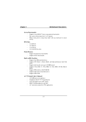
BUS Slots − (1) AGP slot. − (1) CNR slot. − (1) ACR slot − (5) 32-bit PCI bus slots Flash Memory − Supports flash memory functionality. − Supports ESCD functionality. AC'97 Sound Codec Onboard − AC-LINK protocol compliance. − Compliant with any keyboard or mouse activity. Chapter 1 Motherboard ...
BUS Slots − (1) AGP slot. − (1) CNR slot. − (1) ACR slot − (5) 32-bit PCI bus slots Flash Memory − Supports flash memory functionality. − Supports ESCD functionality. AC'97 Sound Codec Onboard − AC-LINK protocol compliance. − Compliant with any keyboard or mouse activity. Chapter 1 Motherboard ...

M7SXF user's manual
Page 10
Chapter 1 Motherboard Description 1.1.2 BIOS − Phoenix legal BIOS. − Supports APM1.2. − Supports USB Function. − Supports ACPI. 1.1.3 Software Operating System − Offers the highest performance for MS-DOS, Windows NT, Windows 2000, Windows 95/98, Windows ME, Windows XP, Novell, LINUX, UNIX, SCO UNIX etc. 1.1.4 Accessories − HDD Cable. − FDD Cable. − Flash Memory Writer for BIOS Update. − JUSB1/JUSB2 Cable (Optional). − Rear I/O Panel for ATX Case (Optional). − Fully Setup Driver CD. 1-5
Chapter 1 Motherboard Description 1.1.2 BIOS − Phoenix legal BIOS. − Supports APM1.2. − Supports USB Function. − Supports ACPI. 1.1.3 Software Operating System − Offers the highest performance for MS-DOS, Windows NT, Windows 2000, Windows 95/98, Windows ME, Windows XP, Novell, LINUX, UNIX, SCO UNIX etc. 1.1.4 Accessories − HDD Cable. − FDD Cable. − Flash Memory Writer for BIOS Update. − JUSB1/JUSB2 Cable (Optional). − Rear I/O Panel for ATX Case (Optional). − Fully Setup Driver CD. 1-5

M7SXF user's manual
Page 16
DRAM Type: 128MB/ 256MB/ 512MB/ 1GB DIMM Module (184 pin) Total Memory Size with unbuffer DIMMs (Only for reference) Total Memory DIMM 1 DIMM 2 DIMM 3 Size (MB) 128 M 128 M ---- ---- 256 M 256 M ---- ---- 512 M 512 M ---- ---- 1 G 1G ---- ---- 256 M 128 M 128 M ---- 512 M 256 M 256 M ---- 1024 M 2 G 384 M 512 M 1G 128 M 512 M 1G ...
DRAM Type: 128MB/ 256MB/ 512MB/ 1GB DIMM Module (184 pin) Total Memory Size with unbuffer DIMMs (Only for reference) Total Memory DIMM 1 DIMM 2 DIMM 3 Size (MB) 128 M 128 M ---- ---- 256 M 256 M ---- ---- 512 M 512 M ---- ---- 1 G 1G ---- ---- 256 M 128 M 128 M ---- 512 M 256 M 256 M ---- 1024 M 2 G 384 M 512 M 1G 128 M 512 M 1G ...

M7SXF user's manual
Page 17
Chapter 1 Motherboard Description 1.4.2 How to install a DIMM Module Single Sided DIMM Double Sided DIMM 1. Insert the DIMM memory modules into the socket at a 90-degree angle, then push down vertically so that it will fit into the slot in place. 1-12 Push the tabs out. The DIMM socket has a " Plastic Safety Tab" ,and the DIMM memory module has an Asymmetrical notch", so the DIMM memory module can only fit into the place. 3. The Mounting Holes and plastic tabs should fit over the edge and hold the DIMM memory modules in one direction. 2.
Chapter 1 Motherboard Description 1.4.2 How to install a DIMM Module Single Sided DIMM Double Sided DIMM 1. Insert the DIMM memory modules into the socket at a 90-degree angle, then push down vertically so that it will fit into the slot in place. 1-12 Push the tabs out. The DIMM socket has a " Plastic Safety Tab" ,and the DIMM memory module has an Asymmetrical notch", so the DIMM memory module can only fit into the place. 3. The Mounting Holes and plastic tabs should fit over the edge and hold the DIMM memory modules in one direction. 2.
M7SXF user's manual
Page 37
... in battery-backed RAM so that it retains the Setup information when the power is a custom version of configuring your computer system's ROM (Read Only Memory) is turned off. BIOS Setup Introduction This manual discussed Award™ Setup program built into the ROM BIOS. The Setup program allows users to the...
... in battery-backed RAM so that it retains the Setup information when the power is a custom version of configuring your computer system's ROM (Read Only Memory) is turned off. BIOS Setup Introduction This manual discussed Award™ Setup program built into the ROM BIOS. The Setup program allows users to the...

M7SXF user's manual
Page 41
... but will not be able to update bios. 2-5 confirmation message will be displayed before proceeding. confirmation Exit Without Saving Abandon all configuration changes to CMOS(memory) and exit setup. Chapter 2 BIOS Setup Set User Password If the Supervisor Password is set , then the User Password will function in the same way...
... but will not be able to update bios. 2-5 confirmation message will be displayed before proceeding. confirmation Exit Without Saving Abandon all configuration changes to CMOS(memory) and exit setup. Chapter 2 BIOS Setup Set User Password If the Supervisor Password is set , then the User Password will function in the same way...

M7SXF user's manual
Page 44
Displays the amount of extended memory detected during boot up . Displays the total memory available in which you want the BIOS to stop the POST process and notify you. Displays the amount of conventional memory detected during boot up . Chapter 2 BIOS Setup Item Halt On Base Memory Extended Memory Total Memory Options All Errors No Errors All, but Keyboard All, but Diskette All, but Disk/ Key N/A N/A N/A Description Select the situation in the system. 2-8
Displays the amount of extended memory detected during boot up . Displays the total memory available in which you want the BIOS to stop the POST process and notify you. Displays the amount of conventional memory detected during boot up . Chapter 2 BIOS Setup Item Halt On Base Memory Extended Memory Total Memory Options All Errors No Errors All, but Keyboard All, but Diskette All, but Disk/ Key N/A N/A N/A Description Select the situation in the system. 2-8

M7SXF user's manual
Page 45
... made to write to protect the IDE Hard Disk boot sector. Advanced BIOS Setup Virus Warning This option allows you may be able to increase memory access time with this function is enabled and an attempt is used to the boot sector, BIOS will display a warning message on the screen and...
... made to write to protect the IDE Hard Disk boot sector. Advanced BIOS Setup Virus Warning This option allows you may be able to increase memory access time with this function is enabled and an attempt is used to the boot sector, BIOS will display a warning message on the screen and...

M7SXF user's manual
Page 48
... For DRAM > 64MB A choice other than Non-OS2 is disabled. The Choices: No (default), Yes. Disabled Optional ROM is only used for OS2 systems with memory exceeding 64MB. Small Logo(EPA) Show This item allows you to enable/disable open the S.M.A.R.T. Chapter 2 BIOS Setup MPS Version Control For OS The BIOS...
... For DRAM > 64MB A choice other than Non-OS2 is disabled. The Choices: No (default), Yes. Disabled Optional ROM is only used for OS2 systems with memory exceeding 64MB. Small Logo(EPA) Show This item allows you to enable/disable open the S.M.A.R.T. Chapter 2 BIOS Setup MPS Version Control For OS The BIOS...

M7SXF user's manual
Page 49
This chipset manages bus speeds and access to choice the system performance which you to system memory resources, such as DRAM and external cache. If you highlight the literal "Press Enter" next to the "Advanced DRAM Control" label and then press the ...
This chipset manages bus speeds and access to choice the system performance which you to system memory resources, such as DRAM and external cache. If you highlight the literal "Press Enter" next to the "Advanced DRAM Control" label and then press the ...

M7SXF user's manual
Page 50
...When synchronous DRAM is installed, the number of clock cycles of the PCI memory address range dedicated for graphics memory address space. Prefetch Caching This item allows you can reserve an area of system memory for more information. AGP Aperture Size Select the size of the peripheral ...128M, 256M. The Choices: Disabled (default), Enabled. The Choices: 2.5T (default), 2T, 3T. When this area is reserved , it cannot be cached. Memory Hole at 15M-16M When enabled, you enable/disable Prefetch Caching. Host cycles that hit the aperture range are installing for ISA adapter ROM. Refer...
...When synchronous DRAM is installed, the number of clock cycles of the PCI memory address range dedicated for graphics memory address space. Prefetch Caching This item allows you can reserve an area of system memory for more information. AGP Aperture Size Select the size of the peripheral ...128M, 256M. The Choices: Disabled (default), Enabled. The Choices: 2.5T (default), 2T, 3T. When this area is reserved , it cannot be cached. Memory Hole at 15M-16M When enabled, you enable/disable Prefetch Caching. Host cycles that hit the aperture range are installing for ISA adapter ROM. Refer...

M7SXF user's manual
Page 52
... in your system software both support Ultra DMA/100, select Auto to enable BIOS support. IDE Burst Mode This item allows you select System Share Memory Size The Choices: 32 MB (default), 4MB, 8MB, 16MB, 64MB. The Choices: Disabled (default), Enabled. If your hard drive and your ...system. The Choices: Enabled (default), Disabled. SiS-900 MAC Address Input System Share Memory Size (Only for M7SXH) This item allows you enable/disable IDE Burst Mode. As well, your operating environment requires a DMA driver (Windows 95 OSR2...
... in your system software both support Ultra DMA/100, select Auto to enable BIOS support. IDE Burst Mode This item allows you select System Share Memory Size The Choices: 32 MB (default), 4MB, 8MB, 16MB, 64MB. The Choices: Disabled (default), Enabled. If your hard drive and your ...system. The Choices: Enabled (default), Disabled. SiS-900 MAC Address Input System Share Memory Size (Only for M7SXH) This item allows you enable/disable IDE Burst Mode. As well, your operating environment requires a DMA driver (Windows 95 OSR2...

M7SXF user's manual
Page 60
... and then is strongly recommended that only experienced users should make any changes to the "Disabled" mode. This node records which allows I/O devices to the memory locations.
... and then is strongly recommended that only experienced users should make any changes to the "Disabled" mode. This node records which allows I/O devices to the memory locations.
M7SXF user's manual
Page 67
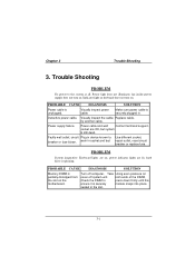
... lit, hard drive is still dead. Visually inspect power cable. Make sure power cable is unplugged. circuit Plug in the slot. 3-1 PROBABLE CAUSE DIAGNOSIS SOLUTION Memory DIMM is securely module snaps into place. both ends of the DIMM, Check the DIMM to press down firmly until the ensure it is partially...
... lit, hard drive is still dead. Visually inspect power cable. Make sure power cable is unplugged. circuit Plug in the slot. 3-1 PROBABLE CAUSE DIAGNOSIS SOLUTION Memory DIMM is securely module snaps into place. both ends of the DIMM, Check the DIMM to press down firmly until the ensure it is partially...

M7SXF user's manual
Page 70
Reinstall memory, make sure that all memory modules are installed in correct sockets. Keyboard failure. PROBLEM PROBABLE CAUSE Keyboard is enabled. Check keys again, if no improvement replace keyboard. 3-4 PROBLEM PROBABLE CAUSE Memory problem. Use anti-virus programs to detect and clean viruses. Computer virus. PROBLEM Screen goes blank periodically. Chapter 3 Trouble Shooting No screen. PROBABLE CAUSE Screen saver is disconnected. DIAGNOSIS SOLUTION Disable screen saver. DIAGNOSIS SOLUTION Reboot computer. DIAGNOSIS SOLUTION Reconnect keyboard.
Reinstall memory, make sure that all memory modules are installed in correct sockets. Keyboard failure. PROBLEM PROBABLE CAUSE Keyboard is enabled. Check keys again, if no improvement replace keyboard. 3-4 PROBLEM PROBABLE CAUSE Memory problem. Use anti-virus programs to detect and clean viruses. Computer virus. PROBLEM Screen goes blank periodically. Chapter 3 Trouble Shooting No screen. PROBABLE CAUSE Screen saver is disconnected. DIAGNOSIS SOLUTION Disable screen saver. DIAGNOSIS SOLUTION Reboot computer. DIAGNOSIS SOLUTION Reconnect keyboard.
M7SXF compatibility test report
Page 2
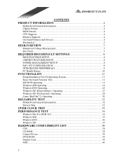
CONTENTS PRODUCT INFORMATION 4 Motherboard General Information 4 Chipset Details ...4 BIOS Details ...4 CPU Supports...4 Memory Supports...4 On-board Features and Devices 4 Mechanical...5 DESIGN REVIEW 7 Mainboard Voltage Measurement 7 Bus Clock...7 REQUIRED BIOS DEFAULT SETTINGS 8 BIOS FEATURES SETUP 8 CHIPSET FEATURES SETUP 8 POWER ...
CONTENTS PRODUCT INFORMATION 4 Motherboard General Information 4 Chipset Details ...4 BIOS Details ...4 CPU Supports...4 Memory Supports...4 On-board Features and Devices 4 Mechanical...5 DESIGN REVIEW 7 Mainboard Voltage Measurement 7 Bus Clock...7 REQUIRED BIOS DEFAULT SETTINGS 8 BIOS FEATURES SETUP 8 CHIPSET FEATURES SETUP 8 POWER ...

M7SXF compatibility test report
Page 3
... TEST-Ver1.0 52 Test Equipment & Environment 52 BCM Stress Test (30 min 52 3 HDD...40 Joystick ...41 Keyboard...42 LAN Card...42 LAN HUB...43 Memory...43 Modem Card ...43 Mouse...44 Monitor ...44 Power Supply ...45 Printer...45 Scanner...45 SCSI Card ...46 Sound Card...46 USB HUB ...46 ZIP...
... TEST-Ver1.0 52 Test Equipment & Environment 52 BCM Stress Test (30 min 52 3 HDD...40 Joystick ...41 Keyboard...42 LAN Card...42 LAN HUB...43 Memory...43 Modem Card ...43 Mouse...44 Monitor ...44 Power Supply ...45 Printer...45 Scanner...45 SCSI Card ...46 Sound Card...46 USB HUB ...46 ZIP...
M7SXF compatibility test report
Page 4
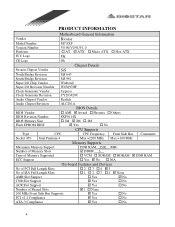
...; No † No 4 PRODUCT INFORMATION Vendor Model Number Version Number Platform FCC Logo Motherboard General Information Biostar M7 SXF V0.90/V0.91/V1.0 † AT ; Award † Phoenix † Others BIOS Revision Number BIOS Memory Size SXF0114X † 1M ; 2M † 4M Flash EPROM BIOS ; DIMM 3 . † VCM ...Yes ; Yes † No CPU Supports Type CPU CPU Frequency Front Side Bus Socket 478 Intel Pentium 4 Max =2200 MHz Max =100 MHz Memory Supports Comments: Maximum Memory Support DDR RAM 1500 (MB) Number of Memory Slots Type of Memory Supported ECC Support ; No ;
...; No † No 4 PRODUCT INFORMATION Vendor Model Number Version Number Platform FCC Logo Motherboard General Information Biostar M7 SXF V0.90/V0.91/V1.0 † AT ; Award † Phoenix † Others BIOS Revision Number BIOS Memory Size SXF0114X † 1M ; 2M † 4M Flash EPROM BIOS ; DIMM 3 . † VCM ...Yes ; Yes † No CPU Supports Type CPU CPU Frequency Front Side Bus Socket 478 Intel Pentium 4 Max =2200 MHz Max =100 MHz Memory Supports Comments: Maximum Memory Support DDR RAM 1500 (MB) Number of Memory Slots Type of Memory Supported ECC Support ; No ;

M7SXF compatibility test report
Page 8
... Control Press Enter Pass System Performance Normal Mode Pass CAS Latency Setting 2.5T Pass DRAM Addr/Cmd Rate AUTO Mode Pass Prefetch Caching Enabled Pass Memory Hole at 15M-16M Disabled Pass AGP Aperture Size 64MB Pass Graphic Window WR Combin Enabled Pass POWER MANAGEMENT SETUP ACPI Function Enabled Pass ACPI...
... Control Press Enter Pass System Performance Normal Mode Pass CAS Latency Setting 2.5T Pass DRAM Addr/Cmd Rate AUTO Mode Pass Prefetch Caching Enabled Pass Memory Hole at 15M-16M Disabled Pass AGP Aperture Size 64MB Pass Graphic Window WR Combin Enabled Pass POWER MANAGEMENT SETUP ACPI Function Enabled Pass ACPI...


