

M7SXF user's manual
Page 3
Contents Introduction 1-1 1. Motherboard Description 1-2 1.1 Features 1-2 1.1.1 Hardware...1-2 1.1.2 BIOS ...1-5 1.1.3 Software...1-5 1.1.4 Accessories ...1-5 1.2 Motherboard Installation 1-6 1.2.1 System Block Diagram 1-6 1.2.2 Layout of Motherboard 1-7 1.2.3 Quick Reference 1-8 1.3 CPU Installation 1-9 1.3.1 CPU Installation Procedure: Socket 478 1-9 1.3.2 CPU Fan Header: JCFAN1 1-10 1.3.3 System Fan Header: JSFAN1 1-10 1.4 RAM Module Installation 1-11 1.4.1 DIMM...1-11 1.4.2 How to install a DIMM Module 1-12 1.5 Slots ...1-13 1.5.1 ACR (Advanced ...
Contents Introduction 1-1 1. Motherboard Description 1-2 1.1 Features 1-2 1.1.1 Hardware...1-2 1.1.2 BIOS ...1-5 1.1.3 Software...1-5 1.1.4 Accessories ...1-5 1.2 Motherboard Installation 1-6 1.2.1 System Block Diagram 1-6 1.2.2 Layout of Motherboard 1-7 1.2.3 Quick Reference 1-8 1.3 CPU Installation 1-9 1.3.1 CPU Installation Procedure: Socket 478 1-9 1.3.2 CPU Fan Header: JCFAN1 1-10 1.3.3 System Fan Header: JSFAN1 1-10 1.4 RAM Module Installation 1-11 1.4.1 DIMM...1-11 1.4.2 How to install a DIMM Module 1-12 1.5 Slots ...1-13 1.5.1 ACR (Advanced ...

M7SXF user's manual
Page 7
...GB for unbuffer DIMMs. − Supports up to 2 unbuffer DIMM DDR333 (only for M7SXF) or up to 3 unbuffer DIMM DDR 266/200. Chapter 1 Motherboard Description 1. Supports up to 2.2 GHz CPU core speeds. The 66MHz AGP 2.0 compliant interface supports 1x, 2x and 4x data transfer... mode. Motherboard Description 1.1 Features 1.1.1 Hardware CPU − − Provides Socket-478. DRAM Memory − Supports 200MHz, 266MHz or 333MHz (only for M7SXF) DDR SDRAM devices. − Supports 128Mb, 256Mb ,512Mb and 1GB technologies. −...
...GB for unbuffer DIMMs. − Supports up to 2 unbuffer DIMM DDR333 (only for M7SXF) or up to 3 unbuffer DIMM DDR 266/200. Chapter 1 Motherboard Description 1. Supports up to 2.2 GHz CPU core speeds. The 66MHz AGP 2.0 compliant interface supports 1x, 2x and 4x data transfer... mode. Motherboard Description 1.1 Features 1.1.1 Hardware CPU − − Provides Socket-478. DRAM Memory − Supports 200MHz, 266MHz or 333MHz (only for M7SXF) DDR SDRAM devices. − Supports 128Mb, 256Mb ,512Mb and 1GB technologies. −...
M7SXF user's manual
Page 9
... Bus Ports and four front panel Universal Serial Bus Ports (optional). − Supports 48 MHz USB. Extended Capabilities Port (ECP). Hardware Monitor Function − Monitors CPU Fan Speed. − Monitors System Voltage. Normal − Supports two serial ports, 16550 UART. − Supports Infrared Data Transmission using IrDA. − Supports 360KB, 720KB...
... Bus Ports and four front panel Universal Serial Bus Ports (optional). − Supports 48 MHz USB. Extended Capabilities Port (ECP). Hardware Monitor Function − Monitors CPU Fan Speed. − Monitors System Voltage. Normal − Supports two serial ports, 16550 UART. − Supports Infrared Data Transmission using IrDA. − Supports 360KB, 720KB...

M7SXF user's manual
Page 13
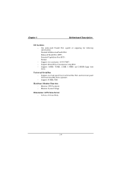
... Connector (JAUXPWR1) F. Back Panel I . IDE Connectors (IDE1-2) D. CD Audio-In Header (JCDIN1) S. CD Audio-In Header (JCDIN2) T. Front USB2.0 Header (*USB20A1) X. X DDR 1 DDR 2 W DDR 3 N O PQ R A. CPU FAN Header (JCFAN1) L. AUX Power Connector (JAUXPWR2) J. Wake-On-LAN Header (JWOL1) V. Floppy Disk Connector (FDD1) E. Chapter 1 1.2.3 Quick Reference G F E DC B Winbond I/O BIOS H LAN Motherboard Description...
... Connector (JAUXPWR1) F. Back Panel I . IDE Connectors (IDE1-2) D. CD Audio-In Header (JCDIN1) S. CD Audio-In Header (JCDIN2) T. Front USB2.0 Header (*USB20A1) X. X DDR 1 DDR 2 W DDR 3 N O PQ R A. CPU FAN Header (JCFAN1) L. AUX Power Connector (JAUXPWR2) J. Wake-On-LAN Header (JWOL1) V. Floppy Disk Connector (FDD1) E. Chapter 1 1.2.3 Quick Reference G F E DC B Winbond I/O BIOS H LAN Motherboard Description...

M7SXF user's manual
Page 14
Press the lever down. 4. Pull the lever sideways away from the socket then raise the lever up to a 90-degree angle. 2. Put the fan on the CPU by buckling it and then put the fan's power port into the JCFAN1, then the installation will be completed. 1-9 Locate Pin A in the CPU. Match Pin A with the white dot/cut edge in the socket and look for the white dot or cut edge then insert the CPU. 3. Chapter 1 Motherboard Description 1.3 CPU Installation 1.3.1 CPU Installation Procedure: Socket 478 CPU 1.
Press the lever down. 4. Pull the lever sideways away from the socket then raise the lever up to a 90-degree angle. 2. Put the fan on the CPU by buckling it and then put the fan's power port into the JCFAN1, then the installation will be completed. 1-9 Locate Pin A in the CPU. Match Pin A with the white dot/cut edge in the socket and look for the white dot or cut edge then insert the CPU. 3. Chapter 1 Motherboard Description 1.3 CPU Installation 1.3.1 CPU Installation Procedure: Socket 478 CPU 1.

M7SXF user's manual
Page 15
SECONDARY IDE CONN. BIOS Winbond I/O USB 2.0 1.3.2 CPU Fan Header: JCFAN1 Pin No. 1 2 3 Assignment Ground +12V Sense 1.3.3 System Fan Header: JSFAN1 Pin No. 1 2 3 Assignment Ground +12V Sense 1 JSFAN1 1-10 FLOPPY DISK CONN. Chapter 1 Motherboard Description CPU Installation Layout Socket 478 1 JCFAN1 DDR 1 DDR 2 DDR 3 LAN SiS 961 PRIMARY IDE CONN.
SECONDARY IDE CONN. BIOS Winbond I/O USB 2.0 1.3.2 CPU Fan Header: JCFAN1 Pin No. 1 2 3 Assignment Ground +12V Sense 1.3.3 System Fan Header: JSFAN1 Pin No. 1 2 3 Assignment Ground +12V Sense 1 JSFAN1 1-10 FLOPPY DISK CONN. Chapter 1 Motherboard Description CPU Installation Layout Socket 478 1 JCFAN1 DDR 1 DDR 2 DDR 3 LAN SiS 961 PRIMARY IDE CONN.

M7SXF user's manual
Page 40
...This selection allows you to reload the BIOS when the system is having problems particularly with to monitor the hardware of your CPU frequency in advance. You will be displayed before defaults are factory settings optimized for this system. A confirmation message will prohibit ...everyone except the supervisor from making changes using the CMOS Setup Utility. The CPU clock ratio should check your system. Set Supervisor Password Setting the supervisor password will be prompted with the boot sequence. Integrated ...
...This selection allows you to reload the BIOS when the system is having problems particularly with to monitor the hardware of your CPU frequency in advance. You will be displayed before defaults are factory settings optimized for this system. A confirmation message will prohibit ...everyone except the supervisor from making changes using the CMOS Setup Utility. The CPU clock ratio should check your system. Set Supervisor Password Setting the supervisor password will be prompted with the boot sequence. Integrated ...

M7SXF user's manual
Page 45
... access time with this function is enabled and an attempt is made to write to the boot sector, BIOS will display a warning message on the CPU/chipset in use, you to choose the VIRUS Warning feature that is used to protect the IDE Hard Disk boot sector...
... access time with this function is enabled and an attempt is made to write to the boot sector, BIOS will display a warning message on the CPU/chipset in use, you to choose the VIRUS Warning feature that is used to protect the IDE Hard Disk boot sector...

M7SXF user's manual
Page 46
... this option will cause an abridged version of the Power On Self-Test (POST) to execute after power on. State after you to enable/disable CPU L2 Cache ECC Checking. Boot Up Floppy Seek Enabling this option reduces the time it takes to determine if they have 40 or 80 tracks.... Chapter 2 BIOS Setup CPU L2 Cache ECC Checking This item allows you power up . Quick Power On Self Test Enabling this option allows you to load the operating system...
... this option will cause an abridged version of the Power On Self-Test (POST) to execute after power on. State after you to enable/disable CPU L2 Cache ECC Checking. Boot Up Floppy Seek Enabling this option reduces the time it takes to determine if they have 40 or 80 tracks.... Chapter 2 BIOS Setup CPU L2 Cache ECC Checking This item allows you power up . Quick Power On Self Test Enabling this option allows you to load the operating system...

M7SXF user's manual
Page 60
... assigned and protects resources from the last one. The system needs to record and update ESCD to operate at speeds nearing the speed of the CPU itself uses when communicating with its own special components. The Choices: Disabled (default), Enabled. 2-24 PCI, or Personal Computer Interconnect, is automatically set to it...
... assigned and protects resources from the last one. The system needs to record and update ESCD to operate at speeds nearing the speed of the CPU itself uses when communicating with its own special components. The Choices: Disabled (default), Enabled. 2-24 PCI, or Personal Computer Interconnect, is automatically set to it...

M7SXF user's manual
Page 63
...;/ 158℉. Current SYSFAN Speed This field displays the current speed SYSTEM fan. 2-27 Current CPU1 Temperature This field displays the current temperature of CPU fan. When this function is enabled, the system will warn you to set the warning temperature of the... CPU in order not to be damaged by the overheated temperature. PC Health Status BIOS Setup CPU Warning Temperature This item allows you if the CPU temperature reaches the warning temperature. Chapter 2 2.8 PC Health Status Figure 8.
...;/ 158℉. Current SYSFAN Speed This field displays the current speed SYSTEM fan. 2-27 Current CPU1 Temperature This field displays the current temperature of CPU fan. When this function is enabled, the system will warn you to set the warning temperature of the... CPU in order not to be damaged by the overheated temperature. PC Health Status BIOS Setup CPU Warning Temperature This item allows you if the CPU temperature reaches the warning temperature. Chapter 2 2.8 PC Health Status Figure 8.

M7SXF user's manual
Page 64
.... Show H/W Monitor in order not to choose. When this function is enabled, the system will show PC health status during POST stage. Chapter 2 BIOS Setup CPU Voltage 3.3V, +5V, +12V Detect the system's voltage status automatically. Shutdown Temperature This item allows you to be damaged by the overheated temperature. The Choices...;/ 167℉. The Choices: None, 1sec, 2sec, 3 sec (default). 2-28 The item offers several delay time for you to set the shutdown temperature of the CPU in POST If your computer contains a monitoring system, it will automatically shutdown if the...
.... Show H/W Monitor in order not to choose. When this function is enabled, the system will show PC health status during POST stage. Chapter 2 BIOS Setup CPU Voltage 3.3V, +5V, +12V Detect the system's voltage status automatically. Shutdown Temperature This item allows you to be damaged by the overheated temperature. The Choices...;/ 167℉. The Choices: None, 1sec, 2sec, 3 sec (default). 2-28 The item offers several delay time for you to set the shutdown temperature of the CPU in POST If your computer contains a monitoring system, it will automatically shutdown if the...

M7SXF user's manual
Page 66
.../SDRAM/PCI Clock This item allows you are selected is not functioning, there are two methods of booting-up the system according to select CPU Host/SDRAM/PCI Clock. If unfortunately, the system's frequency that keep-on pressing the key until the power-on screen showed. Method 1: Clear the CMOS ...
.../SDRAM/PCI Clock This item allows you are selected is not functioning, there are two methods of booting-up the system according to select CPU Host/SDRAM/PCI Clock. If unfortunately, the system's frequency that keep-on pressing the key until the power-on screen showed. Method 1: Clear the CMOS ...
M7SXF compatibility test report
Page 2
CONTENTS PRODUCT INFORMATION 4 Motherboard General Information 4 Chipset Details ...4 BIOS Details ...4 CPU Supports...4 Memory Supports...4 On-board Features and Devices 4 Mechanical...5 DESIGN REVIEW 7 Mainboard Voltage Measurement 7 Bus Clock...7 REQUIRED BIOS DEFAULT SETTINGS 8 BIOS FEATURES SETUP 8 CHIPSET FEATURES ... OVER CLOCK TEST 33 PERFORMANCE TEST 34 Windows Me (For DDR 333 34 Windows ME ...35 Windows2000 ...36 Windows XP ...37 HARDWARE COMPATIBILITY LIST 38 CPU...38 CD-ROM...38 Camera Device...39 DVD-ROM ...39 Display Card ...39 FDD...40 2
CONTENTS PRODUCT INFORMATION 4 Motherboard General Information 4 Chipset Details ...4 BIOS Details ...4 CPU Supports...4 Memory Supports...4 On-board Features and Devices 4 Mechanical...5 DESIGN REVIEW 7 Mainboard Voltage Measurement 7 Bus Clock...7 REQUIRED BIOS DEFAULT SETTINGS 8 BIOS FEATURES SETUP 8 CHIPSET FEATURES ... OVER CLOCK TEST 33 PERFORMANCE TEST 34 Windows Me (For DDR 333 34 Windows ME ...35 Windows2000 ...36 Windows XP ...37 HARDWARE COMPATIBILITY LIST 38 CPU...38 CD-ROM...38 Camera Device...39 DVD-ROM ...39 Display Card ...39 FDD...40 2
M7SXF compatibility test report
Page 4
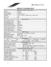
...Support ACR Slot Support † 1 † 2 † 3 † 4 ; No ; Yes † No CPU Supports Type CPU CPU Frequency Front Side Bus Socket 478 Intel Pentium 4 Max =2200 MHz Max =100 MHz Memory Supports Comments: Maximum Memory Support ...DDR RAM 1500 (MB) Number of Memory Slots Type of Memory Supported ECC Support ; PRODUCT INFORMATION Vendor Model Number Version Number Platform FCC Logo Motherboard General Information Biostar...
...Support ACR Slot Support † 1 † 2 † 3 † 4 ; No ; Yes † No CPU Supports Type CPU CPU Frequency Front Side Bus Socket 478 Intel Pentium 4 Max =2200 MHz Max =100 MHz Memory Supports Comments: Maximum Memory Support ...DDR RAM 1500 (MB) Number of Memory Slots Type of Memory Supported ECC Support ; PRODUCT INFORMATION Vendor Model Number Version Number Platform FCC Logo Motherboard General Information Biostar...

M7SXF compatibility test report
Page 5
... Visual Inspection of Soldering Visual Inspection of Layout Screw Holes Line Up with Case Power Connector placement in PCB DIMM/RIMM Socket placement in PCB CPU Socket placement in PCB FAN Connector placement in PCB FDD Connector placement in PCB IDE Connector placement in PCB Front Panel Connectors in PCB PS...
... Visual Inspection of Soldering Visual Inspection of Layout Screw Holes Line Up with Case Power Connector placement in PCB DIMM/RIMM Socket placement in PCB CPU Socket placement in PCB FAN Connector placement in PCB FDD Connector placement in PCB IDE Connector placement in PCB Front Panel Connectors in PCB PS...

M7SXF compatibility test report
Page 8
REQUIRED BIOS DEFAULT SETTINGS Lists Specification Result BIOS FEATURES SETUP Virus Warning Disabled Pass CPU L1 & L2 Cache Enabled Pass CPU L2 Cache ECC Checking Enabled Pass Quick Power On Self Test Enabled Pass First Boot Device Floppy Pass Second Boot Device HDD-0 Pass Third Boot ...
REQUIRED BIOS DEFAULT SETTINGS Lists Specification Result BIOS FEATURES SETUP Virus Warning Disabled Pass CPU L1 & L2 Cache Enabled Pass CPU L2 Cache ECC Checking Enabled Pass Quick Power On Self Test Enabled Pass First Boot Device Floppy Pass Second Boot Device HDD-0 Pass Third Boot ...

M7SXF compatibility test report
Page 11
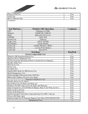
... ME Windows 2000 Professional Windows 2000 Server Windows XP Home Edition Windows XP Professional Linux (Red Hat 7.2) Basic On-board Function Test Test Platform CPU MS-DOS Operating Pentium 4 1.8 GHz Memory Nanya 512 M *1 HDD CDROM QUANTUM 40G TEAC 40X Sound Card Onboard Video Card Onboard LAN Card...Power Turn on ) CMOS Load Default Setup Memory Size Counter Check BIOS Lock Function Warm Boot (HW/SW Reset) System Configuration Review (CPU Type/Cache/SDRAM/HDD...) Prompt Into DOS Mode Typing Some DOS Comment Run Scandisk PS/2 Keyboard Test USB Keyboard Legacy Support Test Boot Floppy...
... ME Windows 2000 Professional Windows 2000 Server Windows XP Home Edition Windows XP Professional Linux (Red Hat 7.2) Basic On-board Function Test Test Platform CPU MS-DOS Operating Pentium 4 1.8 GHz Memory Nanya 512 M *1 HDD CDROM QUANTUM 40G TEAC 40X Sound Card Onboard Video Card Onboard LAN Card...Power Turn on ) CMOS Load Default Setup Memory Size Counter Check BIOS Lock Function Warm Boot (HW/SW Reset) System Configuration Review (CPU Type/Cache/SDRAM/HDD...) Prompt Into DOS Mode Typing Some DOS Comment Run Scandisk PS/2 Keyboard Test USB Keyboard Legacy Support Test Boot Floppy...

M7SXF compatibility test report
Page 12
... Test DMA Controller Test Interrupt Controller Test Timer Test Real Time Clock Test CMOS Validity Test Speaker Test PCI System Test Plug-n-Play Test Multimedia CPU Extensions 12 Pass Pass Pass --Pass Pass Pass --Pass Pass Pass Pass --Pass Pass Pass --Pass --Pass --Pass Pass Pass Pass Pass Pass Pass Pass...
... Test DMA Controller Test Interrupt Controller Test Timer Test Real Time Clock Test CMOS Validity Test Speaker Test PCI System Test Plug-n-Play Test Multimedia CPU Extensions 12 Pass Pass Pass --Pass Pass Pass --Pass Pass Pass Pass --Pass Pass Pass --Pass --Pass --Pass Pass Pass Pass Pass Pass Pass Pass...
M7SXF compatibility test report
Page 14
... 1/5/10/30/60/120 Minutes Then To Do Wake Up Test. Device APM Test ACPI Test I82557 Ethernet chip Comments: Test Platform Windows ME Operating CPU Pentium 4-1.8 GHz Memory SAMSUNG 128M X3 HDD IBM ATA100/ 76.8 G CDROM TEAC 40X Sound Card Onboard Video Card ASUS V3800M PCI Modem Lucent Modem ACR...
... 1/5/10/30/60/120 Minutes Then To Do Wake Up Test. Device APM Test ACPI Test I82557 Ethernet chip Comments: Test Platform Windows ME Operating CPU Pentium 4-1.8 GHz Memory SAMSUNG 128M X3 HDD IBM ATA100/ 76.8 G CDROM TEAC 40X Sound Card Onboard Video Card ASUS V3800M PCI Modem Lucent Modem ACR...


