

M7SXD user's manual
Page 4
... Panel Connector: JPANEL1 1-18 1.6.2 ATX 20-pin Power Connector: JATXPWR1 1-20 1.6.3 ATX 12V Power Connector: JATXPWR2 1-20 1.6.4 AUX Power Connector: JAUXPWR1 1-20 1.6.5 Hard Disk Connectors: IDE1/IDE2 1-21 1.6.6 Floppy Disk Connector: FDD1 1-21 1.6.7 Wake On LAN Header: JWOL1 1-22 1.6.8 Clear CMOS Jumper: JCMOS1 1-22 1.6.9 Front USB Headers: JUSB1/JUSB2 & USB20A1/USB20B1 (Optional) 1-23 1.6.10 DIMM Power Voltage Selection: JDIMMPWR1 1-24 1.7 Peripheral Port 1-25 1.7.1 PS/2 Mouse / Keyboard Connector: JKBMS1 1-25 1.7.2 USB & LAN Connectors: JUSBLAN1 (Optional 1-26 1.7.3 Serial...
... Panel Connector: JPANEL1 1-18 1.6.2 ATX 20-pin Power Connector: JATXPWR1 1-20 1.6.3 ATX 12V Power Connector: JATXPWR2 1-20 1.6.4 AUX Power Connector: JAUXPWR1 1-20 1.6.5 Hard Disk Connectors: IDE1/IDE2 1-21 1.6.6 Floppy Disk Connector: FDD1 1-21 1.6.7 Wake On LAN Header: JWOL1 1-22 1.6.8 Clear CMOS Jumper: JCMOS1 1-22 1.6.9 Front USB Headers: JUSB1/JUSB2 & USB20A1/USB20B1 (Optional) 1-23 1.6.10 DIMM Power Voltage Selection: JDIMMPWR1 1-24 1.7 Peripheral Port 1-25 1.7.1 PS/2 Mouse / Keyboard Connector: JKBMS1 1-25 1.7.2 USB & LAN Connectors: JUSBLAN1 (Optional 1-26 1.7.3 Serial...

M7SXD user's manual
Page 8
... 100 Bus Master Modes. − Supports IDE interface with CD-ROM. − Supports high capacity hard disk drives. − Supports LBA mode. AC'97 Sound Codec Onboard − AC-LINK protocol compliance. − Compliant with AC'97 2.2 specification. − 18-bit full duplex stereo ADC, DACs. − SNR>95 dB through mixer and DAC. − AC-3 playback required for ROM BIOS. Chapter 1 Motherboard Description Shadow RAM − Motherboard is equipped with a memory controller...
... 100 Bus Master Modes. − Supports IDE interface with CD-ROM. − Supports high capacity hard disk drives. − Supports LBA mode. AC'97 Sound Codec Onboard − AC-LINK protocol compliance. − Compliant with AC'97 2.2 specification. − 18-bit full duplex stereo ADC, DACs. − SNR>95 dB through mixer and DAC. − AC-3 playback required for ROM BIOS. Chapter 1 Motherboard Description Shadow RAM − Motherboard is equipped with a memory controller...

M7SXD user's manual
Page 13
...the function is optional. 1-8 Wake-On-LAN Header (JWOL1) V. Chapter 1 1.2.3 Quick Reference G FEDC B BIOS H LAN CHIP Wi nb on d I/O Motherboard Description A Z Y Socket 478 SiS 961 USB 2.0 I J K L PRIMARY IDE CONN. CD Audio-In Header (JCDIN1) S. SDR DIMMs (SDR1-2) J. ACR Slot (ACR1) T. Front Panel Connector (JPANEL1) Z. X DDR 1 W DDR 2 SDR1 V SDR2 NO P Q A. DIMM Power Voltage Selection Header F. CPU FAN Header (JCFAN1) L. M SECONDARY IDE CONN. FLOPPY DISK CONN. Front USB Header (JUSB2) B. PCI BUS Slots (PCI1-5) Q. ATX Power Connector (JATXPWR1...
...the function is optional. 1-8 Wake-On-LAN Header (JWOL1) V. Chapter 1 1.2.3 Quick Reference G FEDC B BIOS H LAN CHIP Wi nb on d I/O Motherboard Description A Z Y Socket 478 SiS 961 USB 2.0 I J K L PRIMARY IDE CONN. CD Audio-In Header (JCDIN1) S. SDR DIMMs (SDR1-2) J. ACR Slot (ACR1) T. Front Panel Connector (JPANEL1) Z. X DDR 1 W DDR 2 SDR1 V SDR2 NO P Q A. DIMM Power Voltage Selection Header F. CPU FAN Header (JCFAN1) L. M SECONDARY IDE CONN. FLOPPY DISK CONN. Front USB Header (JUSB2) B. PCI BUS Slots (PCI1-5) Q. ATX Power Connector (JATXPWR1...

M7SXD user's manual
Page 22
... IDE CONN. FLOPPY DISK CONN. SECONDARY IDE CONN. BIOS Winbond I/O USB 2.0 JWOL1 USB20B1 JPANEL1 JCMOS1 USB20A1 1-17 JUSB2 JUSB1 Chapter 1 Motherboard Description 1.6 Connectors, Headers & Jumpers The connectors, headers and jumpers introduced below provide you to select different system options. Noticeably, a jumper has two or more pins that can be covered by a plastic jumper cap, allowing you lots of capabilities such as power supply, front panel signal revelation, IDE hard disk connection, floppy disk connection, Wake On LAN function and USB connection...
... IDE CONN. FLOPPY DISK CONN. SECONDARY IDE CONN. BIOS Winbond I/O USB 2.0 JWOL1 USB20B1 JPANEL1 JCMOS1 USB20A1 1-17 JUSB2 JUSB1 Chapter 1 Motherboard Description 1.6 Connectors, Headers & Jumpers The connectors, headers and jumpers introduced below provide you to select different system options. Noticeably, a jumper has two or more pins that can be covered by a plastic jumper cap, allowing you lots of capabilities such as power supply, front panel signal revelation, IDE hard disk connection, floppy disk connection, Wake On LAN function and USB connection...

M7SXD user's manual
Page 26
...The second drive on this controller must configure the second hard drive on IDE1 to IDE1. This connector supports the provided floppy drive ribbon cables. 1-21 Chapter 1 Motherboard Description 1.6.5 Hard Disk Connectors: IDE1/IDE2 The motherboard has a 32-bit Enhanced PCI IDE Controller that supports 360K, 720K, 1.2M, 1.44M and 2.88M floppy disk types. IDE1 can connect up to four hard disk drives, a CD-ROM, a 120MB Floppy (reserved for future BIOS) and other devices to slave mode. 1.6.6 Floppy Disk Connector: FDD1 The motherboard provides a standard floppy disk connector (FDC...
...The second drive on this controller must configure the second hard drive on IDE1 to IDE1. This connector supports the provided floppy drive ribbon cables. 1-21 Chapter 1 Motherboard Description 1.6.5 Hard Disk Connectors: IDE1/IDE2 The motherboard has a 32-bit Enhanced PCI IDE Controller that supports 360K, 720K, 1.2M, 1.44M and 2.88M floppy disk types. IDE1 can connect up to four hard disk drives, a CD-ROM, a 120MB Floppy (reserved for future BIOS) and other devices to slave mode. 1.6.6 Floppy Disk Connector: FDD1 The motherboard provides a standard floppy disk connector (FDC...
M7SXD user's manual
Page 38
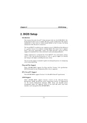
... AWARD BIOS supports Version 1.03 of configuring your computer system's ROM (Read Only Memory) is supported. The Award BIOS™ installed in battery-backed RAM so that it retains the Setup information when the power is intended to the hard disk drives and video monitors can be managed by this manual is turned off. This special information is then stored in your system using Setup. Plug and Play Support These AWARD BIOS supports the Plug and Play Version 1.0A specification. BIOS Setup Introduction This manual...
... AWARD BIOS supports Version 1.03 of configuring your computer system's ROM (Read Only Memory) is supported. The Award BIOS™ installed in battery-backed RAM so that it retains the Setup information when the power is intended to the hard disk drives and video monitors can be managed by this manual is turned off. This special information is then stored in your system using Setup. Plug and Play Support These AWARD BIOS supports the Plug and Play Version 1.0A specification. BIOS Setup Introduction This manual...

M7SXD user's manual
Page 39
... not save changes into CMOS Status Page Setup Menu and Option Page Setup Menu - Supported CPUs This AWARD BIOS supports the Intel Pentium® 4 (Socket 478) processor. Exit Current page and return to Main Menu General help and press to quit. Keystroke Up arrow Down arrow Left arrow Right arrow Esc Move Enter PgUp key PgDn key + Key - Chapter 2 BIOS Setup PCI Bus Support This AWARD BIOS also supports Version 2.1 of the Intel PCI (Peripheral Component Interconnect) local bus specification. The...
... not save changes into CMOS Status Page Setup Menu and Option Page Setup Menu - Supported CPUs This AWARD BIOS supports the Intel Pentium® 4 (Socket 478) processor. Exit Current page and return to Main Menu General help and press to quit. Keystroke Up arrow Down arrow Left arrow Right arrow Esc Move Enter PgUp key PgDn key + Key - Chapter 2 BIOS Setup PCI Bus Support This AWARD BIOS also supports Version 2.1 of the Intel PCI (Peripheral Component Interconnect) local bus specification. The...
M7SXD user's manual
Page 47
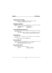
... after you power up . Enabled (default) Enable quick POST. Disabled Normal POST. The Choices: Enabled (default), Disabled. On (default) Numpad is arrow keys. 2-10 Swap Floppy Drive For systems with two floppy drives, this option will cause an abridged version of the Power On Self-Test (POST) to load the operating system from the devices in the sequence selected in these items. The Choices: Floppy, LS120, HDD-0, SCSI, CDROM, HDD-1, HDD-2, HDD-3, ZIP100, LAN, HPT370, Enabled, Disabled. Chapter 2 BIOS Setup CPU L2 Cache...
... after you power up . Enabled (default) Enable quick POST. Disabled Normal POST. The Choices: Enabled (default), Disabled. On (default) Numpad is arrow keys. 2-10 Swap Floppy Drive For systems with two floppy drives, this option will cause an abridged version of the Power On Self-Test (POST) to load the operating system from the devices in the sequence selected in these items. The Choices: Floppy, LS120, HDD-0, SCSI, CDROM, HDD-1, HDD-2, HDD-3, ZIP100, LAN, HPT370, Enabled, Disabled. Chapter 2 BIOS Setup CPU L2 Cache...

M7SXD user's manual
Page 48
... 2 BIOS Setup Gate A20 Option Select if chipset or keyboard controller should control Gate A20. Normal A pin in the keyboard controller controls Gate A20. The Choices: Disabled (default), Enabled. This will repeat at which a keystroke is held down . The Choices: 6 (default), 8,10,12,15,20,24,30. The Choices: Disabled (default), Enabled. 2-11 Typematic Rate Setting When a key is required to access the Setup Utility. Setup (default) A password is held down before it begins to use the CMOS Setup Utility...
... 2 BIOS Setup Gate A20 Option Select if chipset or keyboard controller should control Gate A20. Normal A pin in the keyboard controller controls Gate A20. The Choices: Disabled (default), Enabled. This will repeat at which a keystroke is held down . The Choices: 6 (default), 8,10,12,15,20,24,30. The Choices: Disabled (default), Enabled. 2-11 Typematic Rate Setting When a key is required to access the Setup Utility. Setup (default) A password is held down before it begins to use the CMOS Setup Utility...

M7SXD user's manual
Page 50
... to configure the specific features of the chipset installed on your system have been changed incorrectly. The default settings that came with your system. The Choices: Normal Mode (default), Safe Mode, Fast Mode, Turbo Mode, Ultra Mode. 2-13 If you highlight the literal "Press Enter" next to the "Advanced DRAM Control" label and then press the enter key, it will take you a submenu with the PCI bus. Advanced Chipset Setup Advanced DRAM Control To control the...
... to configure the specific features of the chipset installed on your system have been changed incorrectly. The default settings that came with your system. The Choices: Normal Mode (default), Safe Mode, Fast Mode, Turbo Mode, Ultra Mode. 2-13 If you highlight the literal "Press Enter" next to the "Advanced DRAM Control" label and then press the enter key, it will take you a submenu with the PCI bus. Advanced Chipset Setup Advanced DRAM Control To control the...

M7SXD user's manual
Page 51
... Setting When synchronous DRAM is installed, the number of clock cycles of the Accelerated Graphics Port (AGP) aperture. Memory Hole at 15M-16M When enabled, you are forwarded to the user documentation of the peripheral you can reserve an area of the PCI memory address range dedicated for graphics memory address space. The Choices: 4M, 8M,16M, 32M, 64M (default), 128M, 256M. AGP Aperture Size...
... Setting When synchronous DRAM is installed, the number of clock cycles of the Accelerated Graphics Port (AGP) aperture. Memory Hole at 15M-16M When enabled, you are forwarded to the user documentation of the peripheral you can reserve an area of the PCI memory address range dedicated for graphics memory address space. The Choices: 4M, 8M,16M, 32M, 64M (default), 128M, 256M. AGP Aperture Size...

M7SXD user's manual
Page 52
... Input / Output) fields let you select Internal PCI/IDE. Chapter 2 2.5 Integrated Peripherals Figure 5. Integrated Peripherals BIOS Setup SIS OnChip IDE Device If you highlight the literal "Press Enter" next to the "SIS OnChip IDE Device" label and then press the enter key, it will take you a submenu with the following options: Internal PCI/IDE This item allows you set a PIO mode (0-4) for each of the IDE devices that the onboard IDE interface supports.
... Input / Output) fields let you select Internal PCI/IDE. Chapter 2 2.5 Integrated Peripherals Figure 5. Integrated Peripherals BIOS Setup SIS OnChip IDE Device If you highlight the literal "Press Enter" next to the "SIS OnChip IDE Device" label and then press the enter key, it will take you a submenu with the following options: Internal PCI/IDE This item allows you set a PIO mode (0-4) for each of the IDE devices that the onboard IDE interface supports.

M7SXD user's manual
Page 53
... following options: 2-16 IDE Burst Mode This item allows you to control the onboard S/W modem. The Choices: Disabled (default), Enabled. As well, your system software both support Ultra DMA/100, select Auto to enable BIOS support. SIS OnChip PCI Device If you highlight the literal "Press Enter" next to the "SIS OnChip PCI Device" label and then press the enter key, it is supported by the IDE hard drives in your system. The Choices: Enabled (default), Disabled. Chapter 2 BIOS Setup...
... following options: 2-16 IDE Burst Mode This item allows you to control the onboard S/W modem. The Choices: Disabled (default), Enabled. As well, your system software both support Ultra DMA/100, select Auto to enable BIOS support. SIS OnChip PCI Device If you highlight the literal "Press Enter" next to the "SIS OnChip PCI Device" label and then press the enter key, it is supported by the IDE hard drives in your system. The Choices: Enabled (default), Disabled. Chapter 2 BIOS Setup...

M7SXD user's manual
Page 54
... you to determine which Infrared (IR) function of onboard I /O chip. The Choices: Enabled (default), Disabled. Chapter 2 BIOS Setup Onboard FDC Controller Select Enabled if your system has a floppy disk controller (FDC) installed on the system board and you wish to the IR port. The Choices: Half (default), Full. 2-17 UR2 Duplex Mode Select the value required by the IR device connected to use it. Onboard Serial Port 2 Select an address and corresponding interrupt for...
... you to determine which Infrared (IR) function of onboard I /O chip. The Choices: Enabled (default), Disabled. Chapter 2 BIOS Setup Onboard FDC Controller Select Enabled if your system has a floppy disk controller (FDC) installed on the system board and you wish to the IR port. The Choices: Half (default), Full. 2-17 UR2 Duplex Mode Select the value required by the IR device connected to use it. Onboard Serial Port 2 Select an address and corresponding interrupt for...

M7SXD user's manual
Page 56
... system will need to read /write. The Choices: PCI Slot (default), AGP. You will automatically determine the optimal number of blocks to disable this option determines whether the primary display uses a PCI Slot or an AGP Slot. The Choices: Disabled (default), Enabled. The Choices: Enabled (default), Disabled. Chapter 2 BIOS Setup USB Controller This option should be enabled if your IDE hard drive supports block mode (most new drives do). Select the "Enabled" option if your system has a USB installed on the system board.
... system will need to read /write. The Choices: PCI Slot (default), AGP. You will automatically determine the optimal number of blocks to disable this option determines whether the primary display uses a PCI Slot or an AGP Slot. The Choices: Disabled (default), Enabled. The Choices: Enabled (default), Disabled. Chapter 2 BIOS Setup USB Controller This option should be enabled if your IDE hard drive supports block mode (most new drives do). Select the "Enabled" option if your system has a USB installed on the system board.

M7SXD user's manual
Page 61
... experienced users should make any changes to operate at speeds nearing the speed of the CPU itself uses when communicating with its own special components. The system needs to record and update ESCD to it is a system which resources are reserved in the system BIOS. The Choices: Disabled (default), Enabled. 2-24 Figure 7. Chapter 2 BIOS Setup 2.7 PnP/PCI Configurations This section describes configuring the PCI bus system. These locations (4K...
... experienced users should make any changes to operate at speeds nearing the speed of the CPU itself uses when communicating with its own special components. The system needs to record and update ESCD to it is a system which resources are reserved in the system BIOS. The Choices: Disabled (default), Enabled. 2-24 Figure 7. Chapter 2 BIOS Setup 2.7 PnP/PCI Configurations This section describes configuring the PCI bus system. These locations (4K...

M7SXD user's manual
Page 62
... the "Press Enter" tag, you will be directed to the palette will not show up on cards. Chapter 2 BIOS Setup Resources Controlled By By Choosing "Auto" (default), the system BIOS will detect the system resources and automatically assign the relative IRQ and DMA channel for add-on cards. By Choosing "Manual", the user will allow you to provide boot information and VGA compatibility. IRQ Resources...
... the "Press Enter" tag, you will be directed to the palette will not show up on cards. Chapter 2 BIOS Setup Resources Controlled By By Choosing "Auto" (default), the system BIOS will detect the system resources and automatically assign the relative IRQ and DMA channel for add-on cards. By Choosing "Manual", the user will allow you to provide boot information and VGA compatibility. IRQ Resources...
M7SXD user's manual
Page 69
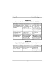
... drive type in ; disk may be used but booting from hard disk is impossible. message, INVALID board. be booted from CD-ROM drive. Run the FDISK program, format the hard drive. Make sure both DRIVE SPECIFICATION. PROBABLE CAUSE DIAGNOSIS SOLUTION Connector between hard When attempting to run Check cable running from drive and system board the FDISK utility you get a disk to do so the hard support. Reformat the hard drive. Chapter 3 Trouble Shooting PROBLEM System does not boot...
... drive type in ; disk may be used but booting from hard disk is impossible. message, INVALID board. be booted from CD-ROM drive. Run the FDISK program, format the hard drive. Make sure both DRIVE SPECIFICATION. PROBABLE CAUSE DIAGNOSIS SOLUTION Connector between hard When attempting to run Check cable running from drive and system board the FDISK utility you get a disk to do so the hard support. Reformat the hard drive. Chapter 3 Trouble Shooting PROBLEM System does not boot...
M7SXD compatibility test report
Page 14
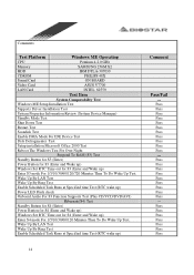
... Wake Up Test. Comments: Test Platform Windows ME Operating CPU Pentium 4-2.0 GHz Memory SAMSUNG 256M X2 HDD IBM DTLA-307030 CDROM PHILIPS 48X Sound Card ON BOARD Video Card ASUS V7700 LAN Card INTEL 82559 Test Item System Comparability Test Windows ME Setup Installation Test Supports Driver Installation Test System Properties Information Review (System Device Manager) Standby Mode Test Shut Down Test Restart Test Scandisk Test Enable DMA Mode For IDE Device Test Disk Defragmenter Test Setup installation...
... Wake Up Test. Comments: Test Platform Windows ME Operating CPU Pentium 4-2.0 GHz Memory SAMSUNG 256M X2 HDD IBM DTLA-307030 CDROM PHILIPS 48X Sound Card ON BOARD Video Card ASUS V7700 LAN Card INTEL 82559 Test Item System Comparability Test Windows ME Setup Installation Test Supports Driver Installation Test System Properties Information Review (System Device Manager) Standby Mode Test Shut Down Test Restart Test Scandisk Test Enable DMA Mode For IDE Device Test Disk Defragmenter Test Setup installation...

M7SXD compatibility test report
Page 16
... Sound Cards For PnP Function Test Pass Audio Drivers Setup Installation Test Pass System Properties Information Review Pass Audio Control Panel Function Test Pass Game Port Test Pass Sound Recorder Test Pass Run MPG Files Pass Speaker Out Quality Test Pass Playing Audio CD Test Pass Playing Wave Test Pass Playing MIDI Test Pass Playing Video Test Pass Playing MP3 Test Pass CNR Slots Test --- PCI Slots Test --- Add LAN Cards...
... Sound Cards For PnP Function Test Pass Audio Drivers Setup Installation Test Pass System Properties Information Review Pass Audio Control Panel Function Test Pass Game Port Test Pass Sound Recorder Test Pass Run MPG Files Pass Speaker Out Quality Test Pass Playing Audio CD Test Pass Playing Wave Test Pass Playing MIDI Test Pass Playing Video Test Pass Playing MP3 Test Pass CNR Slots Test --- PCI Slots Test --- Add LAN Cards...


