
iDEQ 200A user's manual
Page 10
... SPDIF input and output, and the standard audio ports including headphone, microphone, line-in graphics engine and SPDIF jack. And when you open its cover panels, you have the reliability and flexibility of the components like side-blown CPU cooler and special-made power supply that offers powerful computing performance and...
... SPDIF input and output, and the standard audio ports including headphone, microphone, line-in graphics engine and SPDIF jack. And when you open its cover panels, you have the reliability and flexibility of the components like side-blown CPU cooler and special-made power supply that offers powerful computing performance and...
iDEQ 200A user's manual
Page 18
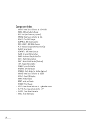
... USB4/USB5 • JCDIN1: CD-Rom Audio-In Header • JCL1: Case Open Connector (Optional) • JUSBV2: Power Source Selection for 1394 • JPANELl: Front Panel Connector • JUSB3: Front USB Header 10
... USB4/USB5 • JCDIN1: CD-Rom Audio-In Header • JCL1: Case Open Connector (Optional) • JUSBV2: Power Source Selection for 1394 • JPANELl: Front Panel Connector • JUSB3: Front USB Header 10
iDEQ 200A user's manual
Page 26
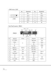
... (+) ( - • C0M2 Header: JC0M2 Pin Assignment Pin Assignment 1 RIN1 2 RIN3 9 00000 1 3 10 O OOOO 2 DOUT2 4 DOUT3 JC0M2 5 Ground 6 RIN2 7 DOUT1 8 RIN4 9 -XRI1 10 NA • Front Panel Connector: JPANEL1 JPANEL1 Pin Assignment 1 +5V Standby 3 Ground 5 IR 7 NA 9 HDD LED (+) 11 HDD LED (-) 13 Ground 15 Reset Control 17 NA 19 NA 21...
... (+) ( - • C0M2 Header: JC0M2 Pin Assignment Pin Assignment 1 RIN1 2 RIN3 9 00000 1 3 10 O OOOO 2 DOUT2 4 DOUT3 JC0M2 5 Ground 6 RIN2 7 DOUT1 8 RIN4 9 -XRI1 10 NA • Front Panel Connector: JPANEL1 JPANEL1 Pin Assignment 1 +5V Standby 3 Ground 5 IR 7 NA 9 HDD LED (+) 11 HDD LED (-) 13 Ground 15 Reset Control 17 NA 19 NA 21...

iDEQ 200A user's manual
Page 30
fronton, Center & Subwooter Serial O 0 -oo► 1101011 PS/2-compatible keyboard SPDIF output 22 3.1r-OVer Your computer offers the following connectors for peripheral devices. Front Panel Connectors : SPDIF Input V eel O -.00► Headphone n IEEE 1394A Microphone USB Ports Figure 3.1 Back Panel Connectors : Line in/Rear Line out/Front Mic/Center & Subwoofer PS/2-compatible mouse O 6 neuron, .. As these devices are provided by third-parties, be sure that they function correctly when connected to your computer before you purchase them.
fronton, Center & Subwooter Serial O 0 -oo► 1101011 PS/2-compatible keyboard SPDIF output 22 3.1r-OVer Your computer offers the following connectors for peripheral devices. Front Panel Connectors : SPDIF Input V eel O -.00► Headphone n IEEE 1394A Microphone USB Ports Figure 3.1 Back Panel Connectors : Line in/Rear Line out/Front Mic/Center & Subwoofer PS/2-compatible mouse O 6 neuron, .. As these devices are provided by third-parties, be sure that they function correctly when connected to your computer before you purchase them.
iDEQ 200A user's manual
Page 32
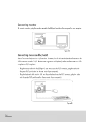
... mouse cable into the USB port (if your mouse uses the PS/2 connector, plug the cable into the green PS/2 port located on the rear panel of your computer). • Plug the keyboard cable into the USB port (if your keyboard uses the PS/2 connector, plug the cable into the VGA... port located on the rear panel of your computer. 00 0 Figure 3.3 Connecting mouse and keyboard Most of mouse and keyboard are PS/2 compliant. Connecting monitor To connect a monitor, plug the monitor...
... mouse cable into the USB port (if your mouse uses the PS/2 connector, plug the cable into the green PS/2 port located on the rear panel of your computer). • Plug the keyboard cable into the USB port (if your keyboard uses the PS/2 connector, plug the cable into the VGA... port located on the rear panel of your computer. 00 0 Figure 3.3 Connecting mouse and keyboard Most of mouse and keyboard are PS/2 compliant. Connecting monitor To connect a monitor, plug the monitor...
iDEQ 200A user's manual
Page 36
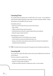
... by the OS. Connecting the printer port: • Match the pins and the shape of your printer manufacturer provides for parallel cable on the rear panel. Connecting LAN You can connect your computer with the locking screw on the connector. • Install the driver from the driver CD or diskette that...
... by the OS. Connecting the printer port: • Match the pins and the shape of your printer manufacturer provides for parallel cable on the rear panel. Connecting LAN You can connect your computer with the locking screw on the connector. • Install the driver from the driver CD or diskette that...
iDEQ 200A user's manual
Page 52
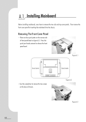
A.1 Installing Mainboard Before installing mainboard, users have to release the front panel bezel. Press the quick joint hooks outward to remove the two-side and top cover panels. Removing The Front Cover Panel • There are four quick joints on the base of front panel bezel as figure A.2. Quick Joints J Figure A.2 a' 4 Figure A.3 44 Then remove the front cover panel for inserting the mainboard into the chassis. Figure A.1 Quick Joints ) OM 00OO • Use the screwdriver to remove the two screws on the reverse side of chassis.
A.1 Installing Mainboard Before installing mainboard, users have to release the front panel bezel. Press the quick joint hooks outward to remove the two-side and top cover panels. Removing The Front Cover Panel • There are four quick joints on the base of front panel bezel as figure A.2. Quick Joints J Figure A.2 a' 4 Figure A.3 44 Then remove the front cover panel for inserting the mainboard into the chassis. Figure A.1 Quick Joints ) OM 00OO • Use the screwdriver to remove the two screws on the reverse side of chassis.
iDEQ 200A user's manual
Page 53
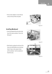
Figure A.4 _ ~; .: r ik v Figure A.5 Figure A.6 45 Installing Mainboard • Insert the mainboard from the side into the base of front cover panel. Use the screwdriver to the Back panel. • After fixing the mainboard on the base of the chassis, you will find there are six mounting holes of screws on the top of the chassis and place it close to fasten the screws. A Appendix • Then use the screwdriver to remove the two screws on the computer chassis and the mainboard.
Figure A.4 _ ~; .: r ik v Figure A.5 Figure A.6 45 Installing Mainboard • Insert the mainboard from the side into the base of front cover panel. Use the screwdriver to the Back panel. • After fixing the mainboard on the base of the chassis, you will find there are six mounting holes of screws on the top of the chassis and place it close to fasten the screws. A Appendix • Then use the screwdriver to remove the two screws on the computer chassis and the mainboard.
iDEQ 200A user's manual
Page 55
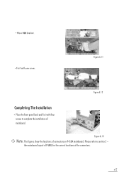
Figure A.12 Completing The Installation • Place the front panel back and fix it with four screws to section 2 -- Figure A.13 Note: The figures show the locations of the connectors. 47 Please refer to complete the installation of mainboard. the mainboard layout of P4ABS for the correct locations of connectors on P4SBA mainboard. • Place HDD bracket. • Fix it with one screw. Figure A.11 -
Figure A.12 Completing The Installation • Place the front panel back and fix it with four screws to section 2 -- Figure A.13 Note: The figures show the locations of the connectors. 47 Please refer to complete the installation of mainboard. the mainboard layout of P4ABS for the correct locations of connectors on P4SBA mainboard. • Place HDD bracket. • Fix it with one screw. Figure A.11 -
