
I945P-A7 v1.x user's manual
Page 2
Table of Contents Chapter 1: Introduction 1 1.1 Motherboard Features 1 1.2 Package Checklist 6 1.3 Layout and Components 7 Chapter 2: Hardware Installation 8 2.1 Installing Central Processing Unit (CPU 8 2.2 FAN Headers 10 2.3 Installing System Memory 11 2.4 Connectors and Slots 12 ...
Table of Contents Chapter 1: Introduction 1 1.1 Motherboard Features 1 1.2 Package Checklist 6 1.3 Layout and Components 7 Chapter 2: Hardware Installation 8 2.1 Installing Central Processing Unit (CPU 8 2.2 FAN Headers 10 2.3 Installing System Memory 11 2.4 Connectors and Slots 12 ...
I945P-A7 v1.x user's manual
Page 3
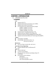
... EM64T). Chipset North Bridge: Intel 945P. Dimensions ATX Form Factor: 24.4cm (W) x 29.7cm (L) Operating System Supporting Supports Windows 2000, and Windows XP. Super I /O functionality. I945P-A7 CHAPTER 1: INTRODUCTION 1.1 MOTHERBOARD FEATURES A. Intel ICH7 (for Rev 1.0).
... EM64T). Chipset North Bridge: Intel 945P. Dimensions ATX Form Factor: 24.4cm (W) x 29.7cm (L) Operating System Supporting Supports Windows 2000, and Windows XP. Super I /O functionality. I945P-A7 CHAPTER 1: INTRODUCTION 1.1 MOTHERBOARD FEATURES A. Intel ICH7 (for Rev 1.0).

I945P-A7 v1.x user's manual
Page 14
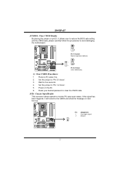
I945P-A7 2.4 CONNECTORS AND SLOTS FDD1: Floppy Disk Connector The motherboard provides a standard floppy disk connector that provides PIO Mode 0~4, Bus Master, and Ultra DMA 33/66/100 functionality. This connector supports the provided floppy drive ribbon cables. 34 33 COM1 2 1 Codec IDE1: Hard Disk Connector (IDE2 and IDE3 are optional.) The motherboard has a 32...
I945P-A7 2.4 CONNECTORS AND SLOTS FDD1: Floppy Disk Connector The motherboard provides a standard floppy disk connector that provides PIO Mode 0~4, Bus Master, and Ultra DMA 33/66/100 functionality. This connector supports the provided floppy drive ribbon cables. 34 33 COM1 2 1 Codec IDE1: Hard Disk Connector (IDE2 and IDE3 are optional.) The motherboard has a 32...
I945P-A7 v1.x user's manual
Page 16
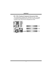
PCI1 PCI2 Codec PCI3 14 This PCI slot is a bus standard for expansion cards. PCI stands for Peripheral Component Interconnect, and it is designated as 32 bits. COM1 I945P-A7 PCI1~PCI3: Peripheral Component Interconnect Slots This motherboard is equipped with 3 standard PCI slots.
PCI1 PCI2 Codec PCI3 14 This PCI slot is a bus standard for expansion cards. PCI stands for Peripheral Component Interconnect, and it is designated as 32 bits. COM1 I945P-A7 PCI1~PCI3: Peripheral Component Interconnect Slots This motherboard is equipped with 3 standard PCI slots.

I945P-A7 v1.x user's manual
Page 22
...) 3 USB- 4 USB- 5 USB+ JUSB3 JUSB4 6 USB+ 2 10 7 Ground 8 Ground Codec 1 9 9 Key 10 NC 20 JUSB3/JUSB4: Front USB Headers This motherboard provides 2 USB 2.0 headers, which allows user to support this function "Power-on Pin 2-3. Note: In order to connect additional USB cable on the PC front... and also can be placed on system via keyboard and mouse", "JKBV1" jumper cap should be connected with internal USB devices, like USB card reader. I945P-A7 JKBV1: Power Source Header for PS/2 Keyboard and Mouse COM1 3 3 1 Pin 1-2 Close 1 +5V for PS/2 keyboard and mouse. 3 Codec...
...) 3 USB- 4 USB- 5 USB+ JUSB3 JUSB4 6 USB+ 2 10 7 Ground 8 Ground Codec 1 9 9 Key 10 NC 20 JUSB3/JUSB4: Front USB Headers This motherboard provides 2 USB 2.0 headers, which allows user to support this function "Power-on Pin 2-3. Note: In order to connect additional USB cable on the PC front... and also can be placed on system via keyboard and mouse", "JKBV1" jumper cap should be connected with internal USB devices, like USB card reader. I945P-A7 JKBV1: Power Source Header for PS/2 Keyboard and Mouse COM1 3 3 1 Pin 1-2 Close 1 +5V for PS/2 keyboard and mouse. 3 Codec...

I945P-A7 v1.x user's manual
Page 23
...- 1 4 Ground 5 RX- 4 6 RX+ 7 Ground Codec 7 SATA2 SATA1 JPANEL1: Front Panel Header This 24-pin connector includes Power-on button IrDA Connector 21 I945P-A7 SATA1~SATA4: Serial ATA Connectors The motherboard has a PCI to connect the PC case's front panel switch functions. COM1 Codec Pin Assignment 1 +5V 3 N/A 5 N/A 7 Speaker 9 HDD LED (+) 11 HDD LED...
...- 1 4 Ground 5 RX- 4 6 RX+ 7 Ground Codec 7 SATA2 SATA1 JPANEL1: Front Panel Header This 24-pin connector includes Power-on button IrDA Connector 21 I945P-A7 SATA1~SATA4: Serial ATA Connectors The motherboard has a PCI to connect the PC case's front panel switch functions. COM1 Codec Pin Assignment 1 +5V 3 N/A 5 N/A 7 Speaker 9 HDD LED (+) 11 HDD LED...
I945P-A7 v1.x user's manual
Page 24
... open signal 2 Ground 2 1 Codec 22 JCI1: Chassis Open Header This connector allows system to avoid damaging the motherboard. 1 COM1 3 Pin 1-2 Close: Normal Operation (default). 1 1 3 Codec 3 Pin 2-3 Close: Clear CMOS data. ※ Clear CMOS Procedures: 1. I945P-A7 JCMOS1: Clear CMOS Header By placing the jumper on pin2-3, it will record to the CMOS and...
... open signal 2 Ground 2 1 Codec 22 JCI1: Chassis Open Header This connector allows system to avoid damaging the motherboard. 1 COM1 3 Pin 1-2 Close: Normal Operation (default). 1 1 3 Codec 3 Pin 2-3 Close: Clear CMOS data. ※ Clear CMOS Procedures: 1. I945P-A7 JCMOS1: Clear CMOS Header By placing the jumper on pin2-3, it will record to the CMOS and...
I945P-A7 v1.x user's manual
Page 25
Make a bootable floppy disk. 2. Download the Flash Utility "AWDFLASH.exe" from Biostar website. 4. Insert the bootable disk into floppy disk. 5. Type "Awdflash xxxx.bf/sn/py/r" in DOS prompt. 8. System will work properly. 23 If the .... In this Case, please follow the procedure below to DOS prompt. 7. Confirm motherboard model and download the respectively BIOS from the Biostar website: www.biostar.com.tw 3. The BIOS has been recovered and will update BIOS automatically and restart. 9. I945P-A7 CHAPTER 4: USEFUL HELP 4.1 AWARD BIOS BEEP CODE Beep Sound One long beep followed...
Make a bootable floppy disk. 2. Download the Flash Utility "AWDFLASH.exe" from Biostar website. 4. Insert the bootable disk into floppy disk. 5. Type "Awdflash xxxx.bf/sn/py/r" in DOS prompt. 8. System will work properly. 23 If the .... In this Case, please follow the procedure below to DOS prompt. 7. Confirm motherboard model and download the respectively BIOS from the Biostar website: www.biostar.com.tw 3. The BIOS has been recovered and will update BIOS automatically and restart. 9. I945P-A7 CHAPTER 4: USEFUL HELP 4.1 AWARD BIOS BEEP CODE Beep Sound One long beep followed...
I945P-A7 v1.x user's manual
Page 26
... 2. Or you can: 1. CPU Overheated If the system shutdown automatically after power on the system again. 24 When the CPU is rotated normally. 3. I945P-A7 B. After confirmed, please follow steps below to avoid a damage of the CPU, and the system may not power on again. Wait for seconds. 3....seconds, that means the CPU protection function has been activated. In this case, please double check: 1. CPU fan is over heated, the motherboard will shutdown automatically to relief the CPU protection function. 1. CPU fan speed is placed evenly with the CPU speed. Plug in the power ...
... 2. Or you can: 1. CPU Overheated If the system shutdown automatically after power on the system again. 24 When the CPU is rotated normally. 3. I945P-A7 B. After confirmed, please follow steps below to avoid a damage of the CPU, and the system may not power on again. Wait for seconds. 3....seconds, that means the CPU protection function has been activated. In this case, please double check: 1. CPU fan is over heated, the motherboard will shutdown automatically to relief the CPU protection function. 1. CPU fan speed is placed evenly with the CPU speed. Plug in the power ...
I945P-A7 v1.x user's manual
Page 31
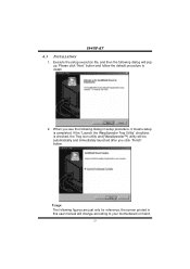
... automatically and immediately launched after you see the following dialog in this user manual will pop up. I945P-A7 6.3 INSTALLATION 1. When you click "Finish" button. Please click "Next" button and follow the default procedure to your motherboard on hand. 29 Execute the setup execution file, and then the following figures are just only...
... automatically and immediately launched after you see the following dialog in this user manual will pop up. I945P-A7 6.3 INSTALLATION 1. When you click "Finish" button. Please click "Next" button and follow the default procedure to your motherboard on hand. 29 Execute the setup execution file, and then the following figures are just only...

