
I945P-A7 v1.x user's manual
Page 3
... Execute Disable Bit Technology (XD). Environment Control initiatives, H/W Monitor Fan Speed Controller ITE's "Smart Guardian" function 1 Hardware CPU Supports LGA 775. Dimensions ATX Form Factor: 24.4cm (W) x 29.7cm (L) Operating System Supporting Supports Windows 2000, and Windows XP. I945P-A7 CHAPTER 1: INTRODUCTION 1.1 MOTHERBOARD FEATURES A.
... Execute Disable Bit Technology (XD). Environment Control initiatives, H/W Monitor Fan Speed Controller ITE's "Smart Guardian" function 1 Hardware CPU Supports LGA 775. Dimensions ATX Form Factor: 24.4cm (W) x 29.7cm (L) Operating System Supporting Supports Windows 2000, and Windows XP. I945P-A7 CHAPTER 1: INTRODUCTION 1.1 MOTHERBOARD FEATURES A.
I945P-A7 v1.x user's manual
Page 8
I945P-A7 B. Supports ACPI Supports USB Function. BIOS & Software BIOS Award legal BIOS. Software Supports Warpspeeder™, 9th Touch™, WINFLASHER™ and FLASHER™. 1.2 PACKAGE CHECKLIST FDD Cable X 1 HDD Cable X 1 User's Manual X 1 Serial ATA Cable X 1 Fully Setup Driver CD X 1 Rear I/O Panel for ATX Case X 1 USB 2.0 Cable X1 (optional) S/PDIF Cable X 1 (optional) IEEE 1394 Cable X 1 (optional) Retention Bracket X 1 (optional) Serial ATA Power Switch Cable X 1 (optional) Dual Video Bridge (BRI-2) Connector X 1 (optional) 6 Supports APM1.2.
I945P-A7 B. Supports ACPI Supports USB Function. BIOS & Software BIOS Award legal BIOS. Software Supports Warpspeeder™, 9th Touch™, WINFLASHER™ and FLASHER™. 1.2 PACKAGE CHECKLIST FDD Cable X 1 HDD Cable X 1 User's Manual X 1 Serial ATA Cable X 1 Fully Setup Driver CD X 1 Rear I/O Panel for ATX Case X 1 USB 2.0 Cable X1 (optional) S/PDIF Cable X 1 (optional) IEEE 1394 Cable X 1 (optional) Retention Bracket X 1 (optional) Serial ATA Power Switch Cable X 1 (optional) Dual Video Bridge (BRI-2) Connector X 1 (optional) 6 Supports APM1.2.
I945P-A7 v1.x user's manual
Page 17
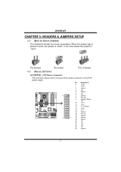
... 23 +5V 24 Ground 15 When the jumper cap is "open". Pin opened Pin closed Pin1-2 closed 3.2 DETAIL SETTINGS JATXPWR1: ATX Power Connector This connector allows user to set up jumpers. I945P-A7 CHAPTER 3: HEADERS & JUMPERS SETUP 3.1 HOW TO SETUP JUMPERS The illustration shows how to connect 24-pin power connector on pins...
... 23 +5V 24 Ground 15 When the jumper cap is "open". Pin opened Pin closed Pin1-2 closed 3.2 DETAIL SETTINGS JATXPWR1: ATX Power Connector This connector allows user to set up jumpers. I945P-A7 CHAPTER 3: HEADERS & JUMPERS SETUP 3.1 HOW TO SETUP JUMPERS The illustration shows how to connect 24-pin power connector on pins...
I945P-A7 v1.x user's manual
Page 18
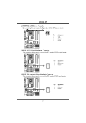
COM1 Pin Assignment 1 +5V 2 SPDIF_OUT 1 3 Ground 3 Codec JSPDIF_IN1 (optional): Digital Audio-in Connector This connector allows user to connect the PCI bracket SPDIF output header. COM1 Pin Assignment 1 +5V 2 SPDIF_IN 1 3 Ground 3 Codec 16 I945P-A7 JATXPWR2: ATX Power Connector By connecting this connector, it will provide +12V to CPU power circuit. 13 COM1 24 Pin Assignment 1 +12V 2 +12V 3 Ground 4 Ground Codec JSPDIF_OUT1: Digital Audio-out Connector This connector allows user to connect the PCI bracket SPDIF input header.
COM1 Pin Assignment 1 +5V 2 SPDIF_OUT 1 3 Ground 3 Codec JSPDIF_IN1 (optional): Digital Audio-in Connector This connector allows user to connect the PCI bracket SPDIF output header. COM1 Pin Assignment 1 +5V 2 SPDIF_IN 1 3 Ground 3 Codec 16 I945P-A7 JATXPWR2: ATX Power Connector By connecting this connector, it will provide +12V to CPU power circuit. 13 COM1 24 Pin Assignment 1 +12V 2 +12V 3 Ground 4 Ground Codec JSPDIF_OUT1: Digital Audio-out Connector This connector allows user to connect the PCI bracket SPDIF input header.