
I945P-A7 v1.x user's manual
Page 2
Table of Contents Chapter 1: Introduction 1 1.1 Motherboard Features 1 1.2 Package Checklist 6 1.3 Layout and Components 7 Chapter 2: Hardware Installation 8 2.1 Installing Central Processing Unit (CPU 8 2.2 FAN Headers 10 2.3 Installing System Memory 11 2.4 Connectors and Slots 12 Chapter 3: Headers & Jumpers Setup 15 3.1 How to Setup Jumpers 15 3.2 Detail Settings 15 Chapter 4: ...
Table of Contents Chapter 1: Introduction 1 1.1 Motherboard Features 1 1.2 Package Checklist 6 1.3 Layout and Components 7 Chapter 2: Hardware Installation 8 2.1 Installing Central Processing Unit (CPU 8 2.2 FAN Headers 10 2.3 Installing System Memory 11 2.4 Connectors and Slots 12 Chapter 3: Headers & Jumpers Setup 15 3.1 How to Setup Jumpers 15 3.2 Detail Settings 15 Chapter 4: ...
I945P-A7 v1.x user's manual
Page 3
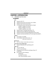
... ATX Form Factor: 24.4cm (W) x 29.7cm (L) Operating System Supporting Supports Windows 2000, and Windows XP. Super I /O functionality. Hardware CPU Supports LGA 775. Supports Intel Pentium 4 processor up to 3.8GHz. Front Side Bus at the following frequency ranges: 533MT/s (133MHz ... South Bridge: Intel ICH7R (for Rev 2.0). Provides the most commonly used legacy Super I /O Chip: ITE IT8712F. I945P-A7 CHAPTER 1: INTRODUCTION 1.1 MOTHERBOARD FEATURES A. Supports Enhanced Intel SpeedStep® Technology (EIST). Supports Intel Extended Memory 64 Technology (Intel EM64T).
... ATX Form Factor: 24.4cm (W) x 29.7cm (L) Operating System Supporting Supports Windows 2000, and Windows XP. Super I /O functionality. Hardware CPU Supports LGA 775. Supports Intel Pentium 4 processor up to 3.8GHz. Front Side Bus at the following frequency ranges: 533MT/s (133MHz ... South Bridge: Intel ICH7R (for Rev 2.0). Provides the most commonly used legacy Super I /O Chip: ITE IT8712F. I945P-A7 CHAPTER 1: INTRODUCTION 1.1 MOTHERBOARD FEATURES A. Supports Enhanced Intel SpeedStep® Technology (EIST). Supports Intel Extended Memory 64 Technology (Intel EM64T).

I945P-A7 v1.x user's manual
Page 10
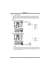
I945P-A7 CHAPTER 2: HARDWARE INSTALLATION 2.1 INSTALLING CENTRAL PROCESSING UNIT (CPU) COM1 Codec CPU1 Special Notice: Remove Pin Cap before installation, and make good preservation for future use. Pin Cap Step 1: Pull the lever sideways away from the socket and then raise the lever up to ensure pin legs won't be damaged. When the CPU is removed, cover the Pin Cap on the empty socket to a 90-degree angle. 8
I945P-A7 CHAPTER 2: HARDWARE INSTALLATION 2.1 INSTALLING CENTRAL PROCESSING UNIT (CPU) COM1 Codec CPU1 Special Notice: Remove Pin Cap before installation, and make good preservation for future use. Pin Cap Step 1: Pull the lever sideways away from the socket and then raise the lever up to ensure pin legs won't be damaged. When the CPU is removed, cover the Pin Cap on the empty socket to a 90-degree angle. 8

I945P-A7 v1.x user's manual
Page 11
Step 4: Put the CPU Fan on CPU should point forwards this black cut edge on socket, and the white dot on the CPU and buckle it. The CPU will fit only in the correct orientation. Step 2-1: Step 2-2: Step 3: Hold the CPU down firmly, and then close the lever to the JCFAN1. Connect the CPU FAN power cable to complete the installation. I945P-A7 Step 2: Look for the black cut edge. This completes the installation. 9
Step 4: Put the CPU Fan on CPU should point forwards this black cut edge on socket, and the white dot on the CPU and buckle it. The CPU will fit only in the correct orientation. Step 2-1: Step 2-2: Step 3: Hold the CPU down firmly, and then close the lever to the JCFAN1. Connect the CPU FAN power cable to complete the installation. I945P-A7 Step 2: Look for the black cut edge. This completes the installation. 9
I945P-A7 v1.x user's manual
Page 12
... cable to the connector while matching the black wire to the fan manufacturer. I945P-A7 2.2 FAN HEADERS These fan headers support cooling-fans built in the computer. It supports 4-pin head connector. When connecting with Smart Fan Control utility. JCFAN1: CPU Fan Header JCFAN1 1 4 COM1 Pin Assignment 1 Ground 2 Power 3 FAN RPM rate sense...
... cable to the connector while matching the black wire to the fan manufacturer. I945P-A7 2.2 FAN HEADERS These fan headers support cooling-fans built in the computer. It supports 4-pin head connector. When connecting with Smart Fan Control utility. JCFAN1: CPU Fan Header JCFAN1 1 4 COM1 Pin Assignment 1 Ground 2 Power 3 FAN RPM rate sense...
I945P-A7 v1.x user's manual
Page 18
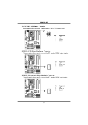
COM1 Pin Assignment 1 +5V 2 SPDIF_OUT 1 3 Ground 3 Codec JSPDIF_IN1 (optional): Digital Audio-in Connector This connector allows user to connect the PCI bracket SPDIF output header. COM1 Pin Assignment 1 +5V 2 SPDIF_IN 1 3 Ground 3 Codec 16 I945P-A7 JATXPWR2: ATX Power Connector By connecting this connector, it will provide +12V to CPU power circuit. 13 COM1 24 Pin Assignment 1 +12V 2 +12V 3 Ground 4 Ground Codec JSPDIF_OUT1: Digital Audio-out Connector This connector allows user to connect the PCI bracket SPDIF input header.
COM1 Pin Assignment 1 +5V 2 SPDIF_OUT 1 3 Ground 3 Codec JSPDIF_IN1 (optional): Digital Audio-in Connector This connector allows user to connect the PCI bracket SPDIF output header. COM1 Pin Assignment 1 +5V 2 SPDIF_IN 1 3 Ground 3 Codec 16 I945P-A7 JATXPWR2: ATX Power Connector By connecting this connector, it will provide +12V to CPU power circuit. 13 COM1 24 Pin Assignment 1 +12V 2 +12V 3 Ground 4 Ground Codec JSPDIF_OUT1: Digital Audio-out Connector This connector allows user to connect the PCI bracket SPDIF input header.
I945P-A7 v1.x user's manual
Page 25
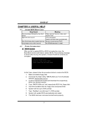
Download the Flash Utility "AWDFLASH.exe" from Biostar website. 4. Make a bootable floppy disk. 2. Type "Awdflash xxxx.bf/sn/py/r" in DOS prompt. 8. Copy "AWDFLASH.exe" and respectively BIOS into floppy drive and press ... card memory bad CPU overheated System will shut down automatically No error found during POST No DRAM detected or install 4.2 EXTRA INFORMATION A. System will boo-up the system, it means the BIOS contents are corrupted. Confirm motherboard model and download the respectively BIOS from the Biostar website: www.biostar.com.tw 3. I945P-A7 CHAPTER 4: USEFUL...
Download the Flash Utility "AWDFLASH.exe" from Biostar website. 4. Make a bootable floppy disk. 2. Type "Awdflash xxxx.bf/sn/py/r" in DOS prompt. 8. Copy "AWDFLASH.exe" and respectively BIOS into floppy drive and press ... card memory bad CPU overheated System will shut down automatically No error found during POST No DRAM detected or install 4.2 EXTRA INFORMATION A. System will boo-up the system, it means the BIOS contents are corrupted. Confirm motherboard model and download the respectively BIOS from the Biostar website: www.biostar.com.tw 3. I945P-A7 CHAPTER 4: USEFUL...
I945P-A7 v1.x user's manual
Page 26
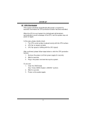
... you can: 1. Power on again. The CPU cooler surface is fulfilling with the CPU surface. 2. Remove the power cord from power supply for seconds. 3. CPU fan is over heated, the motherboard will shutdown automatically to relief the CPU protection function. 1. Wait for seconds. 2. ...Plug in the power cord and boot up the system. In this case, please double check: 1. After confirmed, please follow steps below to avoid a damage of the CPU, and the system may not power on the system again. 24 I945P-A7 B. When the CPU...
... you can: 1. Power on again. The CPU cooler surface is fulfilling with the CPU surface. 2. Remove the power cord from power supply for seconds. 3. CPU fan is over heated, the motherboard will shutdown automatically to relief the CPU protection function. 1. Wait for seconds. 2. ...Plug in the power cord and boot up the system. In this case, please double check: 1. After confirmed, please follow steps below to avoid a damage of the CPU, and the system may not power on the system again. 24 I945P-A7 B. When the CPU...
I945P-A7 v1.x user's manual
Page 30
I945P-A7 CHAPTER 6: WARPSPEEDER™ 6.1 INTRODUCTION [WarpSpeeder™], a new powerful control utility, features three user-friendly functions including Overclock Manager, Overvoltage Manager, and Hardware Monitor. Moreover, to ... If you use Windows XP, you can get detail descriptions about BIOS model and chipsets. The cool Hardware Monitor smartly indicates the temperatures, voltage and CPU fan speed as well as the chipset information. Also, in system fail or hang, [WarpSpeeder™] technology assures the system stability by automatically rebooting the...
I945P-A7 CHAPTER 6: WARPSPEEDER™ 6.1 INTRODUCTION [WarpSpeeder™], a new powerful control utility, features three user-friendly functions including Overclock Manager, Overvoltage Manager, and Hardware Monitor. Moreover, to ... If you use Windows XP, you can get detail descriptions about BIOS model and chipsets. The cool Hardware Monitor smartly indicates the temperatures, voltage and CPU fan speed as well as the chipset information. Also, in system fail or hang, [WarpSpeeder™] technology assures the system stability by automatically rebooting the...
I945P-A7 v1.x user's manual
Page 33
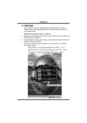
... from 120% ~ above 31 the utility's first window you click the tray icon, [WarpSpeeder™] utility will see is Main Panel. I945P-A7 2. Main Panel contains features as follows: a. Display the CPU Speed, CPU external clock, Memory clock, AGP clock, and PCI clock information. b. c. Main Panel If you will be invoked. Please refer to...
... from 120% ~ above 31 the utility's first window you click the tray icon, [WarpSpeeder™] utility will see is Main Panel. I945P-A7 2. Main Panel contains features as follows: a. Display the CPU Speed, CPU external clock, Memory clock, AGP clock, and PCI clock information. b. c. Main Panel If you will be invoked. Please refer to...
I945P-A7 v1.x user's manual
Page 34
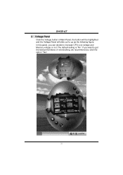
In this panel, you click the option "Yes". 32 The default setting is "No". If you want to get the best performance of overclocking, we recommend you can decide to up as the following figure. I945P-A7 3. Voltage Panel Click the Voltage button in Main Panel, the button will be highlighted and the Voltage Panel will slide out to increase CPU core voltage and Memory voltage or not.
In this panel, you click the option "Yes". 32 The default setting is "No". If you want to get the best performance of overclocking, we recommend you can decide to up as the following figure. I945P-A7 3. Voltage Panel Click the Voltage button in Main Panel, the button will be highlighted and the Voltage Panel will slide out to increase CPU core voltage and Memory voltage or not.


