Setup Manual
Page 2
...1.1 Before You Start 1 1.2 Package Checklist 1 1.3 Motherboard Features 2 1.4 Rear Panel Connectors 3 1.5 Motherboard Layout 4 Chapter 2: Hardware Installation 5 2.1 Installing Central Processing Unit (CPU 5 2.2 FAN Headers 7 2.3 Installing System Memory 8 2.4 Connectors and Slots 10 Chapter 3: Headers & Jumpers Setup 13 3.1 How to Setup Jumpers 13 3.2 Detail Settings 13 Chapter 4: Useful Help 17 4.1 Driver Installation Note 17 4.2 Software 18 4.3 Extra Information 22 4.4 AMI BIOS Beep Code 23 4.5 Troubleshooting 24 Appendix: SPEC In Other...
...1.1 Before You Start 1 1.2 Package Checklist 1 1.3 Motherboard Features 2 1.4 Rear Panel Connectors 3 1.5 Motherboard Layout 4 Chapter 2: Hardware Installation 5 2.1 Installing Central Processing Unit (CPU 5 2.2 FAN Headers 7 2.3 Installing System Memory 8 2.4 Connectors and Slots 10 Chapter 3: Headers & Jumpers Setup 13 3.1 How to Setup Jumpers 13 3.2 Detail Settings 13 Chapter 4: Useful Help 17 4.1 Driver Installation Note 17 4.2 Software 18 4.3 Extra Information 22 4.4 AMI BIOS Beep Code 23 4.5 Troubleshooting 24 Appendix: SPEC In Other...
Setup Manual
Page 3
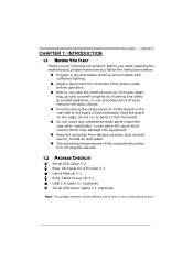
... product. Loose parts will cause short circuits which may be different due to area or your motherboard version. 1 Before you start installing the motherboard, please make sure you follow the instructions below: „ Prepare a dry and stable working environment with sufficient lighting. „ Always disconnect the computer from power outlet before operation. „ Before you for ATX Case X 1 User's Manual X 1 Fully Setup Driver CD X 1 USB 2.0 Cable X1 (optional) Serial ATA Power Cable X 1 (optional) Note...
... product. Loose parts will cause short circuits which may be different due to area or your motherboard version. 1 Before you start installing the motherboard, please make sure you follow the instructions below: „ Prepare a dry and stable working environment with sufficient lighting. „ Always disconnect the computer from power outlet before operation. „ Before you for ATX Case X 1 User's Manual X 1 Fully Setup Driver CD X 1 USB 2.0 Cable X1 (optional) Serial ATA Power Cable X 1 (optional) Note...
Setup Manual
Page 4
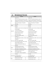
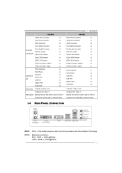
... channels audio out High Definition Audio PCI Express Gen2 x16 Slot x1 PCI Express Gen2 x16 Slot x1 Slots PCI Express Gen2 x1 Slot x2 PCI Express Gen2 x1 Slot x2 2 Motherboard Manual 1.3 MOTHERBOARD FEATURES H61MGC H61MLC Socket 1155 Socket 1155 Intel Core i7/i5/i3/Pentium/Celeron processor Intel Core i7/i5/i3/Pentium/Celeron processor Supports Execute Disable Bit / Enhanced Intel Supports Execute Disable Bit / Enhanced Intel CPU SpeedStep® / Intel Architecture-64 / Extended SpeedStep® / Intel Architecture-64 / Extended Memory 64 Technology / Virtualization Memory...
... channels audio out High Definition Audio PCI Express Gen2 x16 Slot x1 PCI Express Gen2 x16 Slot x1 Slots PCI Express Gen2 x1 Slot x2 PCI Express Gen2 x1 Slot x2 2 Motherboard Manual 1.3 MOTHERBOARD FEATURES H61MGC H61MLC Socket 1155 Socket 1155 Intel Core i7/i5/i3/Pentium/Celeron processor Intel Core i7/i5/i3/Pentium/Celeron processor Supports Execute Disable Bit / Enhanced Intel Supports Execute Disable Bit / Enhanced Intel CPU SpeedStep® / Intel Architecture-64 / Extended SpeedStep® / Intel Architecture-64 / Extended Memory 64 Technology / Virtualization Memory...
Setup Manual
Page 5
... Board CPU Fan Header x1 Connectors System Fan Header x1 Clear CMOS Header x1 USB 2.0 Connector x2 Power Connector (24pin) x1 Power Connector (4pin) x1 PS/2 Keyboard x1 PS/2 Mouse x1 VGA Port x1 Back Panel DVI-D Port x1 I/O LAN Port x1 USB2.0 Port x4 Audio Jack x3 Board Size 175 (W) x 226 (L) mm Windows XP / Vista / 7 OS Support Biostar reserves the right to add or remove support for any OS with or without notice H61MGC / H61MLC H61MLC Printer Port Connector x1 Serial Port Connector x1 SATA Connector x4 Front Panel Connector x1 Front Audio Connector...
... Board CPU Fan Header x1 Connectors System Fan Header x1 Clear CMOS Header x1 USB 2.0 Connector x2 Power Connector (24pin) x1 Power Connector (4pin) x1 PS/2 Keyboard x1 PS/2 Mouse x1 VGA Port x1 Back Panel DVI-D Port x1 I/O LAN Port x1 USB2.0 Port x4 Audio Jack x3 Board Size 175 (W) x 226 (L) mm Windows XP / Vista / 7 OS Support Biostar reserves the right to add or remove support for any OS with or without notice H61MGC / H61MLC H61MLC Printer Port Connector x1 Serial Port Connector x1 SATA Connector x4 Front Panel Connector x1 Front Audio Connector...
Setup Manual
Page 8
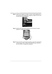
Motherboard Manual Step 3: Look for the triangular cut edge on socket, and the golden dot on the retention frame. The CPU will fit only in the correct orientation. Connect the CPU FAN power cable into the CPU_FAN1 to complete the installation. Step 4: Hold the CPU down firmly, and then lower the lever to locked position to complete the installation. 6 Step 5: Put the CPU Fan and heatsink assembly on the CPU and buckle it on CPU should point forwards this triangular cut edge.
Motherboard Manual Step 3: Look for the triangular cut edge on socket, and the golden dot on the retention frame. The CPU will fit only in the correct orientation. Connect the CPU FAN power cable into the CPU_FAN1 to complete the installation. Step 4: Hold the CPU down firmly, and then lower the lever to locked position to complete the installation. 6 Step 5: Put the CPU Fan and heatsink assembly on the CPU and buckle it on CPU should point forwards this triangular cut edge.
Setup Manual
Page 9
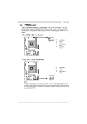
the CPU_FAN1 supports 4-pin head connector. CPU_FAN1: CPU Fan Header Pin Assignment 1 4 1 Ground 2 +12V 3 FAN RPM rate sense 4 Smart Fan Control SYS_FAN1: System Fan Header Pin Assignment 1 Ground 2 +12V 3 FAN RPM rate sense 13 Note: The SYS_FAN1 support 3-pin head connectors; H61MGC / H61MLC 2.2 FAN HEADERS These fan headers support cooling-fans built in the computer. When connecting with wires onto connectors, please note that the red wire is the positive and should be connected to pin#2, and the black wire is Ground and...
the CPU_FAN1 supports 4-pin head connector. CPU_FAN1: CPU Fan Header Pin Assignment 1 4 1 Ground 2 +12V 3 FAN RPM rate sense 4 Smart Fan Control SYS_FAN1: System Fan Header Pin Assignment 1 Ground 2 +12V 3 FAN RPM rate sense 13 Note: The SYS_FAN1 support 3-pin head connectors; H61MGC / H61MLC 2.2 FAN HEADERS These fan headers support cooling-fans built in the computer. When connecting with wires onto connectors, please note that the red wire is the positive and should be connected to pin#2, and the black wire is Ground and...
Setup Manual
Page 11
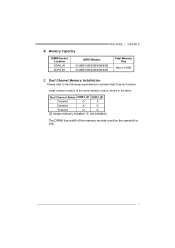
Memory Capacity H61MGC / H61MLC DIMM Socket Location DDR3_A1 DDR3_B1 DDR3 Module 512MB/1GB/2GB/4GB/8GB 512MB/1GB/2GB/4GB/8GB Total Memory Size Max is 16GB. Dual Channel Memory Installation Please refer to the following requirements to activate Dual Channel function: Install memory module of the memory module must be the same(x8 or x16) 9 C. X, not installed.) The DRAM bus width of the same density in pairs, shown in the table. Dual Channel Status DDR3_A1 DDR3_B1 Disabled O X Disabled X O Enabled O O (O means memory installed; B.
Memory Capacity H61MGC / H61MLC DIMM Socket Location DDR3_A1 DDR3_B1 DDR3 Module 512MB/1GB/2GB/4GB/8GB 512MB/1GB/2GB/4GB/8GB Total Memory Size Max is 16GB. Dual Channel Memory Installation Please refer to the following requirements to activate Dual Channel function: Install memory module of the memory module must be the same(x8 or x16) 9 C. X, not installed.) The DRAM bus width of the same density in pairs, shown in the table. Dual Channel Status DDR3_A1 DDR3_B1 Disabled O X Disabled X O Enabled O O (O means memory installed; B.
Setup Manual
Page 12
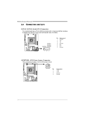
SATA 1 SATA 2 SATA3 SATA4 7 41 Pin Assignment 1 Ground 2 TX+ 3 TX4 Ground 5 RX6 RX+ 7 Ground ATXPWR2: ATX Power Source Connector This connector provides +12V to SATA Controller with 4 channels SATA2 interface, it satisfies the SATA 2.0 spec and with transfer rate of 3.0Gb/s. Motherboard Manual 2.4 CONNECTORS AND SLOTS SATA1~SATA4: Serial ATA Connectors The motherboard has a PCI to CPU power circuit. 2 1 3 4 Pin Assignment 1 +12V 2 +12V 3 Ground 4 Ground 10
SATA 1 SATA 2 SATA3 SATA4 7 41 Pin Assignment 1 Ground 2 TX+ 3 TX4 Ground 5 RX6 RX+ 7 Ground ATXPWR2: ATX Power Source Connector This connector provides +12V to SATA Controller with 4 channels SATA2 interface, it satisfies the SATA 2.0 spec and with transfer rate of 3.0Gb/s. Motherboard Manual 2.4 CONNECTORS AND SLOTS SATA1~SATA4: Serial ATA Connectors The motherboard has a PCI to CPU power circuit. 2 1 3 4 Pin Assignment 1 +12V 2 +12V 3 Ground 4 Ground 10
Setup Manual
Page 13
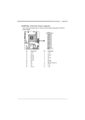
H61MGC / H61MLC ATXPWR1: ATX Power Source Connector This connector allows user to connect 24-pin power connector on the ATX power supply. 12 24 Pin Assignment 13 +3.3V 14 -12V 15 Ground 16 PS_ON 17 Ground 18 Ground 19 Ground 20 NC 21 +5V 22 +5V 23 +5V 24 Ground 1 13 Pin Assignment 1 +3.3V 2 +3.3V 3 Ground 4 +5V 5 Ground 6 +5V 7 Ground 8 PW_OK 9 Standby Voltage+5V 10 +12V 11 +12V 12 +3.3V 11
H61MGC / H61MLC ATXPWR1: ATX Power Source Connector This connector allows user to connect 24-pin power connector on the ATX power supply. 12 24 Pin Assignment 13 +3.3V 14 -12V 15 Ground 16 PS_ON 17 Ground 18 Ground 19 Ground 20 NC 21 +5V 22 +5V 23 +5V 24 Ground 1 13 Pin Assignment 1 +3.3V 2 +3.3V 3 Ground 4 +5V 5 Ground 6 +5V 7 Ground 8 PW_OK 9 Standby Voltage+5V 10 +12V 11 +12V 12 +3.3V 11
Setup Manual
Page 15
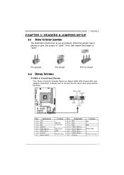
... DETAIL SETTINGS PANEL1: Front Panel Header This 16-pin connector includes Power-on pins, the jumper is "close", if not, that means the jumper is placed on , Reset, HDD LED, Power LED, and speaker connection. SPK R ST H LED Pin Assignment 1 +5V 2 N/A 3 N/A 4 Speaker 5 HDD LED (+) 6 HDD LED (-) 7 Ground 8 Reset control Function Pin 9 Speaker 10 Connector 11 12 Hard drive 13 LED 14 Reset button 15 16 Assignment N/A N/A N/A Power LED (+) Power LED (+) Power LED (-) Power button Ground Function N/A N/A Power LED Power-on button 13 It allows user to set up jumpers...
... DETAIL SETTINGS PANEL1: Front Panel Header This 16-pin connector includes Power-on pins, the jumper is "close", if not, that means the jumper is placed on , Reset, HDD LED, Power LED, and speaker connection. SPK R ST H LED Pin Assignment 1 +5V 2 N/A 3 N/A 4 Speaker 5 HDD LED (+) 6 HDD LED (-) 7 Ground 8 Reset control Function Pin 9 Speaker 10 Connector 11 12 Hard drive 13 LED 14 Reset button 15 16 Assignment N/A N/A N/A Power LED (+) Power LED (+) Power LED (-) Power button Ground Function N/A N/A Power LED Power-on button 13 It allows user to set up jumpers...
Setup Manual
Page 16
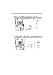
... panel, and also can be connected with the PC front panel. AC'97 connector is not acceptable. Pin Assignment 1 Mic Left in 2 Ground 3 Mic Right in 4 GPIO 5 Right line in 10 9 6 Jack Sense 7 Front Sense 8 Key 9 Left line in 2 1 10 Jack Sense 14 Motherboard Manual F_USB1/F_USB2: Headers for USB 2.0 Ports at Front Panel These headers allow user to connect the front audio output cable with internal USB devices, like USB card...
... panel, and also can be connected with the PC front panel. AC'97 connector is not acceptable. Pin Assignment 1 Mic Left in 2 Ground 3 Mic Right in 4 GPIO 5 Right line in 10 9 6 Jack Sense 7 Front Sense 8 Key 9 Left line in 2 1 10 Jack Sense 14 Motherboard Manual F_USB1/F_USB2: Headers for USB 2.0 Ports at Front Panel These headers allow user to connect the front audio output cable with internal USB devices, like USB card...
Setup Manual
Page 17
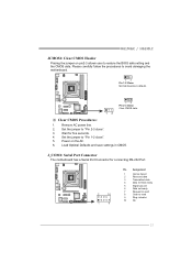
... 7 Request to send 8 Clear to avoid damaging the motherboard. 13 Pin 1-2 Close: Normal Operation (default). 13 13 Pin 2-3 Close: Clear CMOS data. ※ Clear CMOS Procedures: 1. Load Optimal Defaults and save settings in CMOS. H61MGC / H61MLC JCMOS1: Clear CMOS Header Placing the jumper on the AC. 6. Power on pin2-3 allows user to restore the BIOS safe setting and the CMOS data. Set the jumper to "Pin 2-3 close ". 5. J_COM1: Serial Port Connector The motherboard has a Serial Port Connector for five seconds. 4. Remove AC power line. 2. Please carefully...
... 7 Request to send 8 Clear to avoid damaging the motherboard. 13 Pin 1-2 Close: Normal Operation (default). 13 13 Pin 2-3 Close: Clear CMOS data. ※ Clear CMOS Procedures: 1. Load Optimal Defaults and save settings in CMOS. H61MGC / H61MLC JCMOS1: Clear CMOS Header Placing the jumper on the AC. 6. Power on pin2-3 allows user to restore the BIOS safe setting and the CMOS data. Set the jumper to "Pin 2-3 close ". 5. J_COM1: Serial Port Connector The motherboard has a Serial Port Connector for five seconds. 4. Remove AC power line. 2. Please carefully...
Setup Manual
Page 19
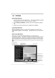
... setup guide will auto detect your motherboard and operating system. The setup guide will need Acrobat Reader to locate and execute the file SETUP.EXE under your optical drive. Please download the latest version of Acrobat Reader software from the paperback manual, we also provide manual in the Driver CD. Click on each device driver to launch the installation program. Note: You will list the compatible driver for better system performance. H61MGC / H61MLC...
... setup guide will auto detect your motherboard and operating system. The setup guide will need Acrobat Reader to locate and execute the file SETUP.EXE under your optical drive. Please download the latest version of Acrobat Reader software from the paperback manual, we also provide manual in the Driver CD. Click on each device driver to launch the installation program. Note: You will list the compatible driver for better system performance. H61MGC / H61MLC...
Setup Manual
Page 20
... desktop. eHot-Line (Optional) eHot-Line is useful for analyzing the problem you may not be collected in forma tion to complete the installation. Double-click the icon to the optical drive. This bl ock will collect the system information which would appear if the Autorun function has been enabled. 2. Select Software Installation, and then click on -screen instructions to a .txt file...
... desktop. eHot-Line (Optional) eHot-Line is useful for analyzing the problem you may not be collected in forma tion to complete the installation. Double-click the icon to the optical drive. This bl ock will collect the system information which would appear if the Autorun function has been enabled. 2. Select Software Installation, and then click on -screen instructions to a .txt file...
Setup Manual
Page 21
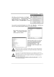
...are not using Outlook Express as your default e-mail client application, you will not share customer's data with other third parties, so please feel free to provide your system information while using eHot-Line service. Open the saved .txt file, you will be saved to a .txt file. Your system... a .txt file and send the file to our tech support with any other e-mail application. Enter the file name and then click "Save". Go to the following web http://www.biostar.com.tw/app/en-us/about/contact.php for your system information including motherboard/BIOS/CPU/video/ device/OS information....
...are not using Outlook Express as your default e-mail client application, you will not share customer's data with other third parties, so please feel free to provide your system information while using eHot-Line service. Open the saved .txt file, you will be saved to a .txt file. Your system... a .txt file and send the file to our tech support with any other e-mail application. Enter the file name and then click "Save". Go to the following web http://www.biostar.com.tw/app/en-us/about/contact.php for your system information including motherboard/BIOS/CPU/video/ device/OS information....
Setup Manual
Page 22
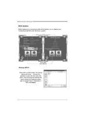
Motherboard Manual BIOS Update BIOS Update is a convenient utility which allows you to a .bin file Update BIOS with a BIOS file Once click on this button, the saving dialog will show. AWARD BIOS Show current BIOS information AMI BIOS Clear CMOS function (Only for AWARD BIOS) Save current BIOS to update your motherboard BIOS under Windows system. Choose the position to save file and enter file name. (We recommend that the file name should be English/number and no longer than 7 characters.) Then click Save. 20
Motherboard Manual BIOS Update BIOS Update is a convenient utility which allows you to a .bin file Update BIOS with a BIOS file Once click on this button, the saving dialog will show. AWARD BIOS Show current BIOS information AMI BIOS Clear CMOS function (Only for AWARD BIOS) Save current BIOS to update your motherboard BIOS under Windows system. Choose the position to save file and enter file name. (We recommend that the file name should be English/number and no longer than 7 characters.) Then click Save. 20
Setup Manual
Page 23
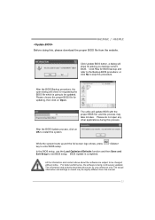
... BIOS. The utility will show for BIOS backup and refer to enter BIOS setup. While the system boots up and the full screen logo shows, press key to the Backup BIOS procedure; The actual information and settings on Open. In the BIOS setup, use the Load Optimized Defaults function and then Save and Exit Setup to be slightly different from the website. Click Update BIOS button, a dialog will show for updating...
... BIOS. The utility will show for BIOS backup and refer to enter BIOS setup. While the system boots up and the full screen logo shows, press key to the Backup BIOS procedure; The actual information and settings on Open. In the BIOS setup, use the Load Optimized Defaults function and then Save and Exit Setup to be slightly different from the website. Click Update BIOS button, a dialog will show for updating...
Setup Manual
Page 24
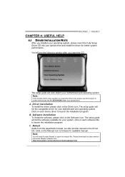
... Clear the CMOS data. (See "Close CMOS Header: JCMOS1" section) 2. Wait for seconds. 2. When the CPU is over heated, the motherboard will shutdown automatically to relief the CPU protection function. 1. CPU fan is placed evenly with the CPU speed. CPU fan speed is fulfilling with the CPU surface. 2. Motherboard Manual 4.3 EXTRA INFORMATION CPU Overheated If the system shuts down automatically after system is powered on for seconds. 3. Plug in the power...
... Clear the CMOS data. (See "Close CMOS Header: JCMOS1" section) 2. Wait for seconds. 2. When the CPU is over heated, the motherboard will shutdown automatically to relief the CPU protection function. 1. CPU fan is placed evenly with the CPU speed. CPU fan speed is fulfilling with the CPU surface. 2. Motherboard Manual 4.3 EXTRA INFORMATION CPU Overheated If the system shuts down automatically after system is powered on for seconds. 3. Plug in the power...

Setup Manual
Page 25
... are used for recovery 4 Flash Programming successful 5 File read error 7 No Flash EPROM detected 10 Flash Erase error 11 Flash Program error 12 "AMIBOOT.ROM" file size error 13 BIOS ROM image mismatch (file layout does not match image present in flash device) POST BIOS Beep Codes Number of Beeps Description 1 Memory refresh timer error 3 Base memory read/write test error 6 Keyboard controller BAT command failed 7 General exception error (processor exception interrupt error) 8 Display memory error (system video adapter) Troubleshooting POST BIOS Beep Codes Number...
... are used for recovery 4 Flash Programming successful 5 File read error 7 No Flash EPROM detected 10 Flash Erase error 11 Flash Program error 12 "AMIBOOT.ROM" file size error 13 BIOS ROM image mismatch (file layout does not match image present in flash device) POST BIOS Beep Codes Number of Beeps Description 1 Memory refresh timer error 3 Base memory read/write test error 6 Keyboard controller BAT command failed 7 General exception error (processor exception interrupt error) 8 Display memory error (system video adapter) Troubleshooting POST BIOS Beep Codes Number...
Setup Manual
Page 26
Contact technical support. 2. Check cable running . Backing up data and applications files. Hard disks can be read, applications can be used, but system 2. System only boots from disk to boot from optical drive. drive. fails to disk controller board. System cannot boot after user installs a 1. second hard drive. 2. There is no power in the standard CMOS setup. 2. Indicator light on , power indicator lights are lit, the DIMM, press down at any time. Keyboard lights Using even pressure on both...
Contact technical support. 2. Check cable running . Backing up data and applications files. Hard disks can be read, applications can be used, but system 2. System only boots from disk to boot from optical drive. drive. fails to disk controller board. System cannot boot after user installs a 1. second hard drive. 2. There is no power in the standard CMOS setup. 2. Indicator light on , power indicator lights are lit, the DIMM, press down at any time. Keyboard lights Using even pressure on both...


