
Setup Manual
Page 1
H55A+ Setup Manual FCC Information and Copyright This equipment has been tested and found in writing. Further the vendor reserves the right to revise this publication and to make changes to the contents here without first obtaining the vendor's approval in this user's manual is not allowed without ...obligation to Part 15 of this user's manual. The content of the FCC Rules. This equipment generates, uses, and can radiate radio frequency energy ...
H55A+ Setup Manual FCC Information and Copyright This equipment has been tested and found in writing. Further the vendor reserves the right to revise this publication and to make changes to the contents here without first obtaining the vendor's approval in this user's manual is not allowed without ...obligation to Part 15 of this user's manual. The content of the FCC Rules. This equipment generates, uses, and can radiate radio frequency energy ...

Setup Manual
Page 3
... on motherboard or the rear side of the computer should be different due to area or your motherboard version. 1 CHAPTER 1: INTRODUCTION H55A+ 1.1 BEFORE YOU START Thank you take the motherboard out from dangerous area, such as heat source, humid air and water. &#... dry and stable working environment with sufficient lighting. „ Always disconnect the computer from power outlet before operation. „ Before you for ATX Case X 1 User's Manual X 1 Fully Setup Driver CD X 1 FDD Cable X 1 (optional) USB 2.0 Cable X1 (optional) Serial ATA Power Cable X 1 (optional) Note: The package...
... on motherboard or the rear side of the computer should be different due to area or your motherboard version. 1 CHAPTER 1: INTRODUCTION H55A+ 1.1 BEFORE YOU START Thank you take the motherboard out from dangerous area, such as heat source, humid air and water. &#... dry and stable working environment with sufficient lighting. „ Always disconnect the computer from power outlet before operation. „ Before you for ATX Case X 1 User's Manual X 1 Fully Setup Driver CD X 1 FDD Cable X 1 (optional) USB 2.0 Cable X1 (optional) Serial ATA Power Cable X 1 (optional) Note: The package...

Setup Manual
Page 4
... Fan power supply (with Smart Fan function) System Fan Header x2 System Fan Power supply Clear CMOS Header x1 Restore CMOS data to 3.0 Gb/s. Motherboard Manual 1.3 MOTHERBOARD FEATURES SPEC Supports Execute Disable Bit / Enhanced Intel Socket 1156 CPU SpeedStep® / Intel Architecture-64 / Extended Intel Core i7 / i5 / i3/ Pentium processor...
... Fan power supply (with Smart Fan function) System Fan Header x2 System Fan Power supply Clear CMOS Header x1 Restore CMOS data to 3.0 Gb/s. Motherboard Manual 1.3 MOTHERBOARD FEATURES SPEC Supports Execute Disable Bit / Enhanced Intel Socket 1156 CPU SpeedStep® / Intel Architecture-64 / Extended Intel Core i7 / i5 / i3/ Pentium processor...

Setup Manual
Page 6
Motherboard Manual 1.5 MOTHERBOARD LAYOUT USBKB1 ATXPWR2 CPU_FAN1 HDMI1 DVI 1 Socket 1156 CP U 1 DDR3_ A2 DDR3_ A1 DDR3_ B2 DDR3_ B1 VGA1 JUSBV1 RJ45USB1 AUDIO1 F_AUDIO1 SYS_FAN2 PEX1_1 PEX 16_1 LAN ATXPWR1 H55 PEX 16_2 CODEC Super I/O JSPD IF OU T 1 J_PRINT1 PCI1 PCI2 JUS BV2 BAT1 JCMOS1 SYS_FAN1 SATA2 SATA4 J_COM1 CIR1 F_USB 3 F_USB2 F_USB1 PANEL1 SATA6 Note: ■ represents the 1st pin. BIOS SATA 1 SATA3 SATA5 4
Motherboard Manual 1.5 MOTHERBOARD LAYOUT USBKB1 ATXPWR2 CPU_FAN1 HDMI1 DVI 1 Socket 1156 CP U 1 DDR3_ A2 DDR3_ A1 DDR3_ B2 DDR3_ B1 VGA1 JUSBV1 RJ45USB1 AUDIO1 F_AUDIO1 SYS_FAN2 PEX1_1 PEX 16_1 LAN ATXPWR1 H55 PEX 16_2 CODEC Super I/O JSPD IF OU T 1 J_PRINT1 PCI1 PCI2 JUS BV2 BAT1 JCMOS1 SYS_FAN1 SATA2 SATA4 J_COM1 CIR1 F_USB 3 F_USB2 F_USB1 PANEL1 SATA6 Note: ■ represents the 1st pin. BIOS SATA 1 SATA3 SATA5 4

Setup Manual
Page 8
Connect the CPU FAN power cable into the CPU_FAN1 to complete the installation. Step 4: Hold the CPU down firmly, and then lower the lever to locked position to complete the installation. 6 Step 5: Put the CPU Fan and heatsink assembly on the CPU and buckle it on CPU should point forwards this triangular cut edge on socket, and the golden dot on the retention frame. The CPU will fit only in the correct orientation. Motherboard Manual Step 3: Look for the triangular cut edge.
Connect the CPU FAN power cable into the CPU_FAN1 to complete the installation. Step 4: Hold the CPU down firmly, and then lower the lever to locked position to complete the installation. 6 Step 5: Put the CPU Fan and heatsink assembly on the CPU and buckle it on CPU should point forwards this triangular cut edge on socket, and the golden dot on the retention frame. The CPU will fit only in the correct orientation. Motherboard Manual Step 3: Look for the triangular cut edge.

Setup Manual
Page 10
DDR3_A2 DDR3_A1 DDR3_B2 DDR3_B1 Motherboard Manual 2.3 INSTALLING SYSTEM MEMORY A. Unlock a DIMM slot by pressing the retaining clips outward. Align a DIMM on the slot such that the notch on the DIMM matches the break on the Slot. 2. Insert the DIMM vertically and firmly into the slot until the retaining chip snap back in place and the DIMM is properly seated. 8 DDR3 module 1.
DDR3_A2 DDR3_A1 DDR3_B2 DDR3_B1 Motherboard Manual 2.3 INSTALLING SYSTEM MEMORY A. Unlock a DIMM slot by pressing the retaining clips outward. Align a DIMM on the slot such that the notch on the DIMM matches the break on the Slot. 2. Insert the DIMM vertically and firmly into the slot until the retaining chip snap back in place and the DIMM is properly seated. 8 DDR3 module 1.

Setup Manual
Page 12
... 23 +5V 24 Ground Pin Assignment 1 +3.3V 2 +3.3V 3 Ground 4 +5V 5 Ground 6 +5V 7 Ground 8 PW_OK 9 Standby Voltage+5V 10 +12V 11 +12V 12 +3.3V 10 Motherboard Manual 2.4 CONNECTORS AND SLOTS SATA1~SATA6: Serial ATA Connectors The motherboard has a PCI to SATA Controller with 6channels SATA interface, it satisfies the SATA 2.0 spec and...
... 23 +5V 24 Ground Pin Assignment 1 +3.3V 2 +3.3V 3 Ground 4 +5V 5 Ground 6 +5V 7 Ground 8 PW_OK 9 Standby Voltage+5V 10 +12V 11 +12V 12 +3.3V 10 Motherboard Manual 2.4 CONNECTORS AND SLOTS SATA1~SATA6: Serial ATA Connectors The motherboard has a PCI to SATA Controller with 6channels SATA interface, it satisfies the SATA 2.0 spec and...

Setup Manual
Page 14
... 2GB/s totally. Maximum theoretical realized bandwidth of 8GB/s simultaneously per direction, for an aggregate of 2.5Gb/s on the data pins. PEX1_1 PEX16_1 PEX16_2 12 Motherboard Manual PEX16_1: PCI-Express Gen2 x16 Slot - PCI-Express Gen2 supports a raw bit-rate of 16GB/s totally. - Maximum theoretical realized bandwidth of 1GB/s simultaneously per direction...
... 2GB/s totally. Maximum theoretical realized bandwidth of 8GB/s simultaneously per direction, for an aggregate of 2.5Gb/s on the data pins. PEX1_1 PEX16_1 PEX16_2 12 Motherboard Manual PEX16_1: PCI-Express Gen2 x16 Slot - PCI-Express Gen2 supports a raw bit-rate of 16GB/s totally. - Maximum theoretical realized bandwidth of 1GB/s simultaneously per direction...

Setup Manual
Page 16
... user to connect additional USB cable on the PC front panel, and also can be connected with internal USB devices, like USB card reader. Motherboard Manual F_USB1/F_USB2/F_USB3: Headers for USB 2.0 Ports at USBKB1/RJ45USB1.
... user to connect additional USB cable on the PC front panel, and also can be connected with internal USB devices, like USB card reader. Motherboard Manual F_USB1/F_USB2/F_USB3: Headers for USB 2.0 Ports at USBKB1/RJ45USB1.

Setup Manual
Page 18
... 1 Carrier detect 2 Received data 3 Transmitted data 4 Data terminal ready 5 Signal ground 6 Data set ready 7 Request to send 8 Clear to connector printer on the PC. Motherboard Manual J_PRINT1: Printer Port Connector This header allows you to send 9 Ring indicator 10 NC 16
... 1 Carrier detect 2 Received data 3 Transmitted data 4 Data terminal ready 5 Signal ground 6 Data set ready 7 Request to send 8 Clear to connector printer on the PC. Motherboard Manual J_PRINT1: Printer Port Connector This header allows you to send 9 Ring indicator 10 NC 16

Setup Manual
Page 20
... install the driver for better system performance. A. C. Click on each software title to launch the installation program. You will list the software available for available manual. The setup guide will see the following window after you insert the Driver CD, please use file browser to open the... manual file. Manual Aside from http://www.adobe.com /produ cts/a crobat /reads tep2 .html 18 Click on the Software icon. Note: If this window didn't show up ...
... install the driver for better system performance. A. C. Click on each software title to launch the installation program. You will list the software available for available manual. The setup guide will see the following window after you insert the Driver CD, please use file browser to open the... manual file. Manual Aside from http://www.adobe.com /produ cts/a crobat /reads tep2 .html 18 Click on the Software icon. Note: If this window didn't show up ...

Setup Manual
Page 22
... a saving dialog appears asking you to provide your system information including motherboard/BIOS/CPU/video/ device/OS information. Motherboard Manual After filling up this information to the following web http://www.biostar.com.tw/app/en-us/about/contact.php for your default e-mail client application, you may need to save this...
... a saving dialog appears asking you to provide your system information including motherboard/BIOS/CPU/video/ device/OS information. Motherboard Manual After filling up this information to the following web http://www.biostar.com.tw/app/en-us/about/contact.php for your default e-mail client application, you may need to save this...

Setup Manual
Page 24
... doing this, please download the proper BIOS file from this manual. 22 After the BIOS Update process, click on Clear CMOS first. or click No to skip this process. After the BIOS Backup procedure, the open ...
... doing this, please download the proper BIOS file from this manual. 22 After the BIOS Update process, click on Clear CMOS first. or click No to skip this process. After the BIOS Backup procedure, the open ...

Setup Manual
Page 26
... right appears. To enter the utility, press during the POST process. After the update process, the utility will lead to system boot failure. 24 Motherboard Manual BIO-Flasher BIO-Flasher is built in the BIOS chip. Select the proper BIOS file and press then to perform the BIOS update process. 6. BIOS...
... right appears. To enter the utility, press during the POST process. After the update process, the utility will lead to system boot failure. 24 Motherboard Manual BIO-Flasher BIO-Flasher is built in the BIOS chip. Select the proper BIOS file and press then to perform the BIOS update process. 6. BIOS...
Setup Manual
Page 28
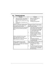
... in the standard CMOS setup. 2. check the drive type in . All hard disks are securely plugged in; fan of are running from optical drive. Motherboard Manual 4.5 TROUBLESHOOTING Probable Solution 1. Screen message shows "Invalid Configuration" or "CMOS Failure." Back up the hard drive is in the system. 1.
... in the standard CMOS setup. 2. check the drive type in . All hard disks are securely plugged in; fan of are running from optical drive. Motherboard Manual 4.5 TROUBLESHOOTING Probable Solution 1. Screen message shows "Invalid Configuration" or "CMOS Failure." Back up the hard drive is in the system. 1.

Bios Setup
Page 1
H55A+ BIOS Manual BIOS Setup 1 1 Main Menu 3 2 Advanced Menu 8 3 PCIPnP Menu 22 4 Boot Menu 25 5 Chipset Menu 28 6 Performance Menu 33 7 Exit Menu 36 i
H55A+ BIOS Manual BIOS Setup 1 1 Main Menu 3 2 Advanced Menu 8 3 PCIPnP Menu 22 4 Boot Menu 25 5 Chipset Menu 28 6 Performance Menu 33 7 Exit Menu 36 i

Bios Setup
Page 2
... by a battery so that it retains theSetup information when the power is to describe the settings in the AMI BIOS Setup program on this manual will to CMOS RAM. ACPI Support AMI ACPI BIOS support Version 1.0/2.0 of the EPA Green PC specification. T his AMI BIOS supports the ...Plug and Play Version 1.0A specification. T he power of CMOS RAM is supplied by Microso ft, Intel and T oshiba. 1 H55A+ BIOS Manual BIOS Setup Introduction T he purpose of this manual is turned off. BIOS activates at the first stag e o f the booting process, loading and executing the operating system. T he...
... by a battery so that it retains theSetup information when the power is to describe the settings in the AMI BIOS Setup program on this manual will to CMOS RAM. ACPI Support AMI ACPI BIOS support Version 1.0/2.0 of the EPA Green PC specification. T his AMI BIOS supports the ...Plug and Play Version 1.0A specification. T he power of CMOS RAM is supplied by Microso ft, Intel and T oshiba. 1 H55A+ BIOS Manual BIOS Setup Introduction T he purpose of this manual is turned off. BIOS activates at the first stag e o f the booting process, loading and executing the operating system. T he...

Bios Setup
Page 3
Navigation Keys for any mistakes found in this manual is subject to be chang ed without notice. We will not be responsible for ... under the Exit Menu. Supported CP Us T his AMI BIOS also supports Version 2.3 of the motherboard. H55A+ BIOS Manual PCI Bus Support T his AMI BIOS supports the Intel CPU. Using Setup When starting up the computer, ... Rate III Synchronous DRAM) is being continuously updated. z T he BIOS information described in this user's manual and any settings, please load the default settings to enter the BIOS setup utility. T he content of this...
Navigation Keys for any mistakes found in this manual is subject to be chang ed without notice. We will not be responsible for ... under the Exit Menu. Supported CP Us T his AMI BIOS also supports Version 2.3 of the motherboard. H55A+ BIOS Manual PCI Bus Support T his AMI BIOS supports the Intel CPU. Using Setup When starting up the computer, ... Rate III Synchronous DRAM) is being continuously updated. z T he BIOS information described in this user's manual and any settings, please load the default settings to enter the BIOS setup utility. T he content of this...

Bios Setup
Page 4
... Time Set the system internal clock. System Time System Date > IDE/SATA Configuration [ 00:00:00] [Fri 01/01/2010] Select Screen Select Item +- H55A+ BIOS Manual 1 Main Menu Once you set the date. 3 Main Advanced BIOS SETUP UTILITY PCIPnP Boot Chipset Performance Exit System Overview AMI BIOS Version :01.01.01...
... Time Set the system internal clock. System Time System Date > IDE/SATA Configuration [ 00:00:00] [Fri 01/01/2010] Select Screen Select Item +- H55A+ BIOS Manual 1 Main Menu Once you set the date. 3 Main Advanced BIOS SETUP UTILITY PCIPnP Boot Chipset Performance Exit System Overview AMI BIOS Version :01.01.01...

Bios Setup
Page 5
... item allows you to choose the SAT A operation mode. Options: Compatible (Default) / Enhanced SATA#2 Configuration T his item allows you to control the onboard SAT A controller. H55A+ BIOS Manual IDE/S ATA Configuration T he BIOS will automatically detect the presence of detailed options. There is a sub-menu fo r each SAT A/IDE device.
... item allows you to choose the SAT A operation mode. Options: Compatible (Default) / Enhanced SATA#2 Configuration T his item allows you to control the onboard SAT A controller. H55A+ BIOS Manual IDE/S ATA Configuration T he BIOS will automatically detect the presence of detailed options. There is a sub-menu fo r each SAT A/IDE device.

