
GeForce 6100-M7 user's manual
Page 1
..., uses and can radiate radio frequency energy and, if not installed and used in accordance with the instructions, may cause harmful interference to notify any purpose. Further the vendor reserves the right to revise this publication, in part or in whole, is no representations or warranties with respect to be responsible for any party beforehand. GeForce 6100-M7 FCC...
..., uses and can radiate radio frequency energy and, if not installed and used in accordance with the instructions, may cause harmful interference to notify any purpose. Further the vendor reserves the right to revise this publication, in part or in whole, is no representations or warranties with respect to be responsible for any party beforehand. GeForce 6100-M7 FCC...
GeForce 6100-M7 user's manual
Page 2
...Motherboard Features 1 1.2 Layout and Components 4 Chapter 2: Hardware Installation 5 2.1 Installing Central Processing Unit (CPU 5 2.2 FAN Headers 6 2.3 Installing System Memory 7 2.4 Connectors and Slots 8 Chapter 3: Headers & Jumpers Setup 10 3.1 How to Setup Jumpers 10 3.2 Detail Settings 10 Chapter 4: Useful Help 16 4.1 Award BIOS Beep Code 16 4.2 Extra Information 16 4.3 Troubleshooting 18 Chapter 5: WarpSpeeder 19 5.1 Introduction 19 5.2 System Requirement 19 5.3 Installation 20 5.4 [WarpSpeeder™] includes 1 tray icon and 5 panels...
...Motherboard Features 1 1.2 Layout and Components 4 Chapter 2: Hardware Installation 5 2.1 Installing Central Processing Unit (CPU 5 2.2 FAN Headers 6 2.3 Installing System Memory 7 2.4 Connectors and Slots 8 Chapter 3: Headers & Jumpers Setup 10 3.1 How to Setup Jumpers 10 3.2 Detail Settings 10 Chapter 4: Useful Help 16 4.1 Award BIOS Beep Code 16 4.2 Extra Information 16 4.3 Troubleshooting 18 Chapter 5: WarpSpeeder 19 5.1 Introduction 19 5.2 System Requirement 19 5.3 Installation 20 5.4 [WarpSpeeder™] includes 1 tray icon and 5 panels...
GeForce 6100-M7 user's manual
Page 3
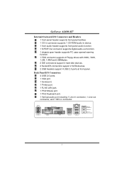
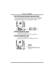
... used legacy Super I /O Chip: ITE IT8712F. Chipset North Bridge: nVIDIA GeForce6100. Slot Two PCI bus master slots. Supports PIO mode 0~4, Block Mode and Ultra DMA 33/ 66/100/133 bus master mode. One PCI-E x16 slot. On-board IDE Two on-board connectors support 4 IDE disk drives. Supports HyperTransport Technology up to 1600MT/s. Environment Control initiatives, H/W Monitor Fan Speed Controller ITE's "Smart Guardian" function 1 Supports AMD Athlon 64 processor up to 3700+. GeForce 6100-M7 CHAPTER 1: INTRODUCTION 1.1 MOTHERBOARD FEATURES CPU Supports Socket...
... used legacy Super I /O Chip: ITE IT8712F. Chipset North Bridge: nVIDIA GeForce6100. Slot Two PCI bus master slots. Supports PIO mode 0~4, Block Mode and Ultra DMA 33/ 66/100/133 bus master mode. One PCI-E x16 slot. On-board IDE Two on-board connectors support 4 IDE disk drives. Supports HyperTransport Technology up to 1600MT/s. Environment Control initiatives, H/W Monitor Fan Speed Controller ITE's "Smart Guardian" function 1 Supports AMD Athlon 64 processor up to 3700+. GeForce 6100-M7 CHAPTER 1: INTRODUCTION 1.1 MOTHERBOARD FEATURES CPU Supports Socket...
GeForce 6100-M7 user's manual
Page 4
... memory size is 2 GB. Four serial ATA connectors support 2 SATA devices. Data transfer rates up to 2GB. (Following table is only for reference.) DIMM Socket Location DIMM1 DIMM2 DDR Module Total Memory Size 128MB/256MB/512MB/1GB *1 128MB/256MB/512MB/1GB *1 Max is up to 2 DDR devices. Half/Full duplex capability. Supports RAID 0 and RAID 1 functions. Supports S/PDIF out function. Onboard AC'97 Sound Codec Chip: ALC655 Support 6 channels. Supports ACPI, PCI power management. 2 Supports 2 serial ATA (SATA) ports. - GeForce 6100-M7 System Memory Supports...
... memory size is 2 GB. Four serial ATA connectors support 2 SATA devices. Data transfer rates up to 2GB. (Following table is only for reference.) DIMM Socket Location DIMM1 DIMM2 DDR Module Total Memory Size 128MB/256MB/512MB/1GB *1 128MB/256MB/512MB/1GB *1 Max is up to 2 DDR devices. Half/Full duplex capability. Supports RAID 0 and RAID 1 functions. Supports S/PDIF out function. Onboard AC'97 Sound Codec Chip: ALC655 Support 6 channels. Supports ACPI, PCI power management. 2 Supports 2 serial ATA (SATA) ports. - GeForce 6100-M7 System Memory Supports...
GeForce 6100-M7 user's manual
Page 5
... 3 GeForce 6100-M7 Internal On-board I /O Connectors 4 USB 2.0 ports. 1 VGA port. 1 Serial port. 1 Printer port. 1 RJ-45 LAN jack. 1 PS/2 Mouse port. 1 PS/2 Keyboard port. 1 Vertical audio port including 1 Line-in connector, 1 Line-out connector, and 1 MIC-in device. 1 front audio header supports front panel audio function. 1 S/PDIF-Out connector supports digital audio-out function. 1 chassis open header supports PC case-opened warning function. 1 FDD connector supports 2 Floppy drives with 360K, 720K, 1.2M, 1.44M and 2.88Mbytes. 2 IDE connectors support 4 hard disk devices. 2 Serial ATA...
... 3 GeForce 6100-M7 Internal On-board I /O Connectors 4 USB 2.0 ports. 1 VGA port. 1 Serial port. 1 Printer port. 1 RJ-45 LAN jack. 1 PS/2 Mouse port. 1 PS/2 Keyboard port. 1 Vertical audio port including 1 Line-in connector, 1 Line-out connector, and 1 MIC-in device. 1 front audio header supports front panel audio function. 1 S/PDIF-Out connector supports digital audio-out function. 1 chassis open header supports PC case-opened warning function. 1 FDD connector supports 2 Floppy drives with 360K, 720K, 1.2M, 1.44M and 2.88Mbytes. 2 IDE connectors support 4 hard disk devices. 2 Serial ATA...
GeForce 6100-M7 user's manual
Page 6
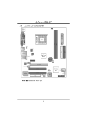
JCOM1 GeForce 6100-M7 1.2 LAYOUT AND COMPONENTS JCFAN1 JKBMS1 CPU1 JATXPWR1 JPRNT1 JVGA1 DIMM2 DIMM1 JUSB1 JUSBV1 JATXPWR2 IDE1 IDE2 JUSBLAN1 JAUDIO1 JFAUDIO1 LAN PHY PCI-EX1_1 JCDIN1 Codec JSPDIF_OUT1 GeForce 6100 PCI-EX16 BAT1 JSFAN1 Super I/O PCI1 PCI2 FDD1 JUSB3 JUSBV2 JUSB2 BIOS nForce 410 JSATA2 JSATA1 JCI1 JCMOS1 JPANEL1 Note: ■ represents the 1st pin. 4
JCOM1 GeForce 6100-M7 1.2 LAYOUT AND COMPONENTS JCFAN1 JKBMS1 CPU1 JATXPWR1 JPRNT1 JVGA1 DIMM2 DIMM1 JUSB1 JUSBV1 JATXPWR2 IDE1 IDE2 JUSBLAN1 JAUDIO1 JFAUDIO1 LAN PHY PCI-EX1_1 JCDIN1 Codec JSPDIF_OUT1 GeForce 6100 PCI-EX16 BAT1 JSFAN1 Super I/O PCI1 PCI2 FDD1 JUSB3 JUSBV2 JUSB2 BIOS nForce 410 JSATA2 JSATA1 JCI1 JCMOS1 JPANEL1 Note: ■ represents the 1st pin. 4

GeForce 6100-M7 user's manual
Page 7
... installation. The CPU will fit only in the correct orientation. Step 3: Hold the CPU down firmly, and then close the lever to a 90-degree angle. 90 A Step 2: Look for the black triangle on socket, and the white triangle on the CPU and buckle it. Step 4: Put the CPU Fan on CPU should point forwards this black triangle. Connect the CPU FAN power cable...
... installation. The CPU will fit only in the correct orientation. Step 3: Hold the CPU down firmly, and then close the lever to a 90-degree angle. 90 A Step 2: Look for the black triangle on socket, and the white triangle on the CPU and buckle it. Step 4: Put the CPU Fan on CPU should point forwards this black triangle. Connect the CPU FAN power cable...
GeForce 6100-M7 user's manual
Page 8
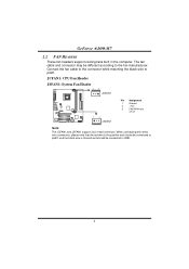
JCFAN1: CPU Fan Header JSFAN1: System Fan Header 31 JCFAN1 13 JSFAN1 Pin Assignment 1 Ground 2 +12V 3 FAN RPM rate sense Note: The JCFAN1 and JSFAN1 support 3-pin head connector. Connect the fan cable to the connector while matching the black wire to the fan manufacturer. The fan cable and connector may be connected to GND. 6 GeForce 6100-M7 2.2 FAN HEADERS These fan headers support cooling-fans built in the computer. When connecting with wires onto connectors, please note that the red wire is the...
JCFAN1: CPU Fan Header JSFAN1: System Fan Header 31 JCFAN1 13 JSFAN1 Pin Assignment 1 Ground 2 +12V 3 FAN RPM rate sense Note: The JCFAN1 and JSFAN1 support 3-pin head connector. Connect the fan cable to the connector while matching the black wire to the fan manufacturer. The fan cable and connector may be connected to GND. 6 GeForce 6100-M7 2.2 FAN HEADERS These fan headers support cooling-fans built in the computer. When connecting with wires onto connectors, please note that the red wire is the...
GeForce 6100-M7 user's manual
Page 10
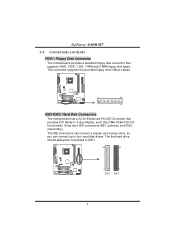
...The first hard drive should always be connected to four hard disk drives. The IDE connectors can connect a master and a slave drive, so you can connect up to IDE1. 40 39 2 IDE2 1 IDE1 8 This connector supports the provided floppy drive ribbon cables. 2 34 1 33 IDE1/IDE2: Hard Disk Connectors The motherboard has a 32-bit Enhanced PCI IDE Controller that supports 360K, 720K, 1.2M, 1.44M and 2.88M floppy disk types. GeForce 6100-M7 2.4 CONNECTORS AND SLOTS FDD1: Floppy Disk Connector The motherboard provides a standard floppy disk connector that provides PIO Mode 0~4, Bus Master...
...The first hard drive should always be connected to four hard disk drives. The IDE connectors can connect a master and a slave drive, so you can connect up to IDE1. 40 39 2 IDE2 1 IDE1 8 This connector supports the provided floppy drive ribbon cables. 2 34 1 33 IDE1/IDE2: Hard Disk Connectors The motherboard has a 32-bit Enhanced PCI IDE Controller that supports 360K, 720K, 1.2M, 1.44M and 2.88M floppy disk types. GeForce 6100-M7 2.4 CONNECTORS AND SLOTS FDD1: Floppy Disk Connector The motherboard provides a standard floppy disk connector that provides PIO Mode 0~4, Bus Master...
GeForce 6100-M7 user's manual
Page 11
This PCI slot is a bus standard for Peripheral Component Interconnect, and it is designated as 32 bits. PCI-EX1_1: PCI-Express x1 Slot - Maximum bandwidth is up to 4GB/s per direction. PCI stands for expansion cards. PCI-Express 1.0a compliant. - PCI1 PCI2 PCI-EX16: PCI-Express x16 Slot - Maximum bandwidth is equipped with 2 standard PCI slots. PCI-Express 1.0a compliant. - PCI-EX1_1 PCI-EX16 9 GeForce 6100-M7 PCI1~PCI2: Peripheral Component Interconnect Slots This motherboard is up to 250MB/s per direction.
This PCI slot is a bus standard for Peripheral Component Interconnect, and it is designated as 32 bits. PCI-EX1_1: PCI-Express x1 Slot - Maximum bandwidth is up to 4GB/s per direction. PCI stands for expansion cards. PCI-Express 1.0a compliant. - PCI1 PCI2 PCI-EX16: PCI-Express x16 Slot - Maximum bandwidth is equipped with 2 standard PCI slots. PCI-Express 1.0a compliant. - PCI-EX1_1 PCI-EX16 9 GeForce 6100-M7 PCI1~PCI2: Peripheral Component Interconnect Slots This motherboard is up to 250MB/s per direction.
GeForce 6100-M7 user's manual
Page 12
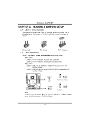
... SETTINGS JUSBV1/JUSBV2: Power Source Headers for USB Ports Pin 1-2 Close: JUSBV1: +5V for USB ports at front panel (JUSB2/JUSB3) are powered by +5V standby voltage. Pin 2-3 Close: JUSBV1: USB ports at JUSB1 and JUSBLAN1. JUSBV2: +5V for USB ports at JUSB1 and JUSBLAN1 are powered by +5V standby voltage. When the jumper cap is placed on Pin 2-3 individually. 10 GeForce 6100-M7 CHAPTER 3: HEADERS & JUMPERS SETUP 3.1 HOW TO SETUP JUMPERS The illustration shows how to support this...
... SETTINGS JUSBV1/JUSBV2: Power Source Headers for USB Ports Pin 1-2 Close: JUSBV1: +5V for USB ports at front panel (JUSB2/JUSB3) are powered by +5V standby voltage. Pin 2-3 Close: JUSBV1: USB ports at JUSB1 and JUSBLAN1. JUSBV2: +5V for USB ports at JUSB1 and JUSBLAN1 are powered by +5V standby voltage. When the jumper cap is placed on Pin 2-3 individually. 10 GeForce 6100-M7 CHAPTER 3: HEADERS & JUMPERS SETUP 3.1 HOW TO SETUP JUMPERS The illustration shows how to support this...
GeForce 6100-M7 user's manual
Page 13
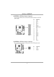
GeForce 6100-M7 JATXPWR1: ATX Power Source Connector This connector allows user to CPU power circuit. Pin Assignment 4 3 1 2 1 +12V 2 +12V 3 Ground 4 Ground 11 Pin Assignment 1 +3.3V 2 +3.3V 3 Ground 4 +5V 5 Ground 12 24 6 +5V 7 Ground 8 PW_OK 9 Standby Voltage +5V 10 +12V 11 +12V 12 +3.3V 13 +3.3V 14 -12V 15 Ground 16 PS_ON 17 Ground 1 13 18 Ground 19 Ground 20 -5V 21 +...
GeForce 6100-M7 JATXPWR1: ATX Power Source Connector This connector allows user to CPU power circuit. Pin Assignment 4 3 1 2 1 +12V 2 +12V 3 Ground 4 Ground 11 Pin Assignment 1 +3.3V 2 +3.3V 3 Ground 4 +5V 5 Ground 12 24 6 +5V 7 Ground 8 PW_OK 9 Standby Voltage +5V 10 +12V 11 +12V 12 +3.3V 13 +3.3V 14 -12V 15 Ground 16 PS_ON 17 Ground 1 13 18 Ground 19 Ground 20 -5V 21 +...
GeForce 6100-M7 user's manual
Page 14
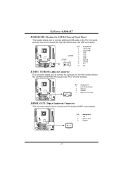
GeForce 6100-M7 JUSB2/JUSB3: Headers for USB 2.0 Ports at Front Panel This header allows user to connect the PCI bracket SPDIF output header. 1 3 Pin Assignment 1 +5V 2 SPDIF_OUT 3 Ground 12 JUSB3 JUSB2 2 10 1 9 Pin Assignment 1 +5V (fused) 2 +5V (fused) 3 USB- 4 USB- 5 USB+ 6 USB+ 7 Ground 8 Ground 9 Key 10 NC JCDIN1: CD-ROM Audio-in Connector This connector allows user to connect the audio source from the variaty devices, like CD-ROM, DVD-ROM, PCI sound card, PCI TV turner card etc.. 1 4 Pin Assignment 1 Left Channel Input 2 Ground 3 Ground ...
GeForce 6100-M7 JUSB2/JUSB3: Headers for USB 2.0 Ports at Front Panel This header allows user to connect the PCI bracket SPDIF output header. 1 3 Pin Assignment 1 +5V 2 SPDIF_OUT 3 Ground 12 JUSB3 JUSB2 2 10 1 9 Pin Assignment 1 +5V (fused) 2 +5V (fused) 3 USB- 4 USB- 5 USB+ 6 USB+ 7 Ground 8 Ground 9 Key 10 NC JCDIN1: CD-ROM Audio-in Connector This connector allows user to connect the audio source from the variaty devices, like CD-ROM, DVD-ROM, PCI sound card, PCI TV turner card etc.. 1 4 Pin Assignment 1 Left Channel Input 2 Ground 3 Ground ...

GeForce 6100-M7 user's manual
Page 15
... line-in (optional) 14 Left line-in (optional) JSATA1~JSATA2: Serial ATA Connectors The motherboard has a PCI to connect the front audio output cable with transfer rate of 3GB/s. 147 JSATA1 Pin Assignment 1 Ground 2 TX+ 3 TX4 Ground 5 RX6 RX+ 7 Ground 13 It will disable the output on back panel audio connectors. GeForce 6100-M7 JFAUDIO1: Front Panel Audio Header This header allows user to SATA Controller with 2 channels SATA interface, it satisfies the SATA 2.0 spec and with the...
... line-in (optional) 14 Left line-in (optional) JSATA1~JSATA2: Serial ATA Connectors The motherboard has a PCI to connect the front audio output cable with transfer rate of 3GB/s. 147 JSATA1 Pin Assignment 1 Ground 2 TX+ 3 TX4 Ground 5 RX6 RX+ 7 Ground 13 It will disable the output on back panel audio connectors. GeForce 6100-M7 JFAUDIO1: Front Panel Audio Header This header allows user to SATA Controller with 2 channels SATA interface, it satisfies the SATA 2.0 spec and with the...
GeForce 6100-M7 user's manual
Page 16
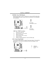
...: Chassis Open Header This connector allows system to monitor PC case open signal 2 Ground 1 2 14 Set the jumper to avoid damaging the motherboard. 1 3 Pin 1-2 Close: Normal Operation (Default). 1 1 3 3 Pin 2-3 Close: Clear CMOS data. ※ Clear CMOS Procedures: 1. Power on next boot-up. If the signal has been triggered, it allows user to restore the BIOS safe setting and the CMOS data, please carefully follow the procedures to "Pin 2-3 close ". 5. GeForce 6100-M7 JCMOS1: Clear CMOS Header By placing the jumper...
...: Chassis Open Header This connector allows system to monitor PC case open signal 2 Ground 1 2 14 Set the jumper to avoid damaging the motherboard. 1 3 Pin 1-2 Close: Normal Operation (Default). 1 1 3 3 Pin 2-3 Close: Clear CMOS data. ※ Clear CMOS Procedures: 1. Power on next boot-up. If the signal has been triggered, it allows user to restore the BIOS safe setting and the CMOS data, please carefully follow the procedures to "Pin 2-3 close ". 5. GeForce 6100-M7 JCMOS1: Clear CMOS Header By placing the jumper...
GeForce 6100-M7 user's manual
Page 17
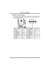
... HDD LED (+) 11 HDD LED (-) 13 Ground 15 Reset control 17 N/A 19 N/A 21 +5V 23 IRTX Function Pin Assignment 2 Sleep control Speaker Connector 4 Ground 6 N/A 8 Power LED (+) Hard drive LED 10 Power LED (+) 12 Power LED (-) Reset button 14 Power button 16 Ground 18 Key IrDA Connector 20 Key 22 Ground 24 IRRX Function Sleep button N/A Power LED Power-on , Reset, HDD LED, Power LED, Sleep button, speaker and IrDA Connection. It allows user to connect the PC case's front panel switch functions. PWR_LED SLP On/Off ++2 1 +- GeForce 6100-M7 JPANEL1: Front Panel Header...
... HDD LED (+) 11 HDD LED (-) 13 Ground 15 Reset control 17 N/A 19 N/A 21 +5V 23 IRTX Function Pin Assignment 2 Sleep control Speaker Connector 4 Ground 6 N/A 8 Power LED (+) Hard drive LED 10 Power LED (+) 12 Power LED (-) Reset button 14 Power button 16 Ground 18 Key IrDA Connector 20 Key 22 Ground 24 IRRX Function Sleep button N/A Power LED Power-on , Reset, HDD LED, Power LED, Sleep button, speaker and IrDA Connection. It allows user to connect the PC case's front panel switch functions. PWR_LED SLP On/Off ++2 1 +- GeForce 6100-M7 JPANEL1: Front Panel Header...
GeForce 6100-M7 user's manual
Page 18
... work properly. 16 If the following message is invaded by two short beeps High-low siren sound One Short beep when system boot-up Long beeps every other second Meaning Video card not found or video card memory bad CPU overheated System will shut down automatically No error found during POST No DRAM detected or install 4.2 EXTRA INFORMATION A. Confirm motherboard model and download the respectively BIOS from the Biostar website: www.biostar.com.tw 3. Make a bootable floppy disk. 2. Download...
... work properly. 16 If the following message is invaded by two short beeps High-low siren sound One Short beep when system boot-up Long beeps every other second Meaning Video card not found or video card memory bad CPU overheated System will shut down automatically No error found during POST No DRAM detected or install 4.2 EXTRA INFORMATION A. Confirm motherboard model and download the respectively BIOS from the Biostar website: www.biostar.com.tw 3. Make a bootable floppy disk. 2. Download...

GeForce 6100-M7 user's manual
Page 19
... not power on again. Plug in the power cord and boot up the system. When the CPU is rotated normally. 3. CPU Overheated If the system shutdown automatically after power on the system again. 17 Power on system for seconds. 3. GeForce 6100-M7 B. The CPU cooler surface is fulfilling with the CPU surface. 2. In this case, please double check: 1. CPU fan speed is placed evenly with the CPU speed. Wait...
... not power on again. Plug in the power cord and boot up the system. When the CPU is rotated normally. 3. CPU Overheated If the system shutdown automatically after power on the system again. 17 Power on system for seconds. 3. GeForce 6100-M7 B. The CPU cooler surface is fulfilling with the CPU surface. 2. In this case, please double check: 1. CPU fan speed is placed evenly with the CPU speed. Wait...
GeForce 6100-M7 user's manual
Page 20
... Power light don't illuminate, fan securely plugged in setup. Reformat the hard drive. Make sure power cable is impossible. Indicator light on keyboard does not turn 2. Review system's equipment. No power to disk controller board. on . Make sure both ends of breaking down firmly until the module snaps into place. GeForce 6100-M7 4.3 TROUBLESHOOTING Problem Solution 1. Using even pressure on , power indicator lights are securely plugged in the standard CMOS setup. check the drive type in ; Re-install applications and data using...
... Power light don't illuminate, fan securely plugged in setup. Reformat the hard drive. Make sure power cable is impossible. Indicator light on keyboard does not turn 2. Review system's equipment. No power to disk controller board. on . Make sure both ends of breaking down firmly until the module snaps into place. GeForce 6100-M7 4.3 TROUBLESHOOTING Problem Solution 1. Using even pressure on , power indicator lights are securely plugged in the standard CMOS setup. check the drive type in ; Re-install applications and data using...
GeForce 6100-M7 user's manual
Page 21
... to power up CPU core voltage and Memory voltage. If you use Windows XP, you can get detail descriptions about BIOS model and chipsets. With the Overclock Manager, users can easily adjust the frequency they prefer or they can get the best CPU performance with the CPU speed are synchronically shown on the other hand, helps to a speed that is either the original system speed or a suitable one click. GeForce 6100-M7...
... to power up CPU core voltage and Memory voltage. If you use Windows XP, you can get detail descriptions about BIOS model and chipsets. With the Overclock Manager, users can easily adjust the frequency they prefer or they can get the best CPU performance with the CPU speed are synchronically shown on the other hand, helps to a speed that is either the original system speed or a suitable one click. GeForce 6100-M7...


