Setup Manual
Page 2
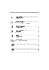
Table of Contents Chapter 1: Introduction 1 1.1 Before You Start 1 1.2 Package Checklist 1 1.3 Motherboard Features 2 1.4 Rear Panel Connectors 3 1.5 Motherboard Layout 4 Chapter 2: Hardware Installation 5 2.1 Installing Central Processing Unit (CPU 5 2.2 FAN Headers 7 2.3 Installing System Memory 8 2.4 Connectors and Slots 10 Chapter 3: Headers & Jumpers Setup 13 3.1 How to ...
Table of Contents Chapter 1: Introduction 1 1.1 Before You Start 1 1.2 Package Checklist 1 1.3 Motherboard Features 2 1.4 Rear Panel Connectors 3 1.5 Motherboard Layout 4 Chapter 2: Hardware Installation 5 2.1 Installing Central Processing Unit (CPU 5 2.2 FAN Headers 7 2.3 Installing System Memory 8 2.4 Connectors and Slots 10 Chapter 3: Headers & Jumpers Setup 13 3.1 How to ...
Setup Manual
Page 3
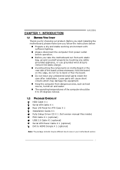
... 0 to 45 degrees Celsius. 1.2 PACKAGE CHECKLIST HDD Cable X 1 Serial ATA Cable X 1 Rear I/O Panel for choosing our product. CHAPTER 1: INTRODUCTION G41D3G 1.1 BEFORE YOU START Thank you take the motherboard out from anti-static bag, ground yourself properly by touching any unfastened small parts inside ) FDD Cable X 1 (optional) USB 2.0 Cable X1 (optional...„ Do not leave any safely grounded appliance, or use grounded wrist strap to remove the static charge. „ Avoid touching the components on motherboard or the rear side of the computer should be different due to area or your...
... 0 to 45 degrees Celsius. 1.2 PACKAGE CHECKLIST HDD Cable X 1 Serial ATA Cable X 1 Rear I/O Panel for choosing our product. CHAPTER 1: INTRODUCTION G41D3G 1.1 BEFORE YOU START Thank you take the motherboard out from anti-static bag, ground yourself properly by touching any unfastened small parts inside ) FDD Cable X 1 (optional) USB 2.0 Cable X1 (optional...„ Do not leave any safely grounded appliance, or use grounded wrist strap to remove the static charge. „ Avoid touching the components on motherboard or the rear side of the computer should be different due to area or your...

Setup Manual
Page 4
Motherboard Manual 1.3 MOTHERBOARD FEATURES SPEC LGA 775 Intel Core2Duo / Core2Quad / Supports Execute Disable Bit / Enhanced Intel CPU Pentium Dual-Core / Celeron Dual-Core / SpeedStep® / Intel Architecture-64 / ...
Motherboard Manual 1.3 MOTHERBOARD FEATURES SPEC LGA 775 Intel Core2Duo / Core2Quad / Supports Execute Disable Bit / Enhanced Intel CPU Pentium Dual-Core / Celeron Dual-Core / SpeedStep® / Intel Architecture-64 / ...

Setup Manual
Page 6
Motherboard Manual 1.5 MOTHERBOARD LAYOUT KBMS1 LGA775 VGA1 ATXPWR2 CPU1 CPU_FAN1 ATXPWR1 D D R 3_A 1 D D R 3_B 1 DVI1 JUSBV1 USB1 LAN RJ45USB1 Intel G41 IDE1 AUDIO1 F_AUDIO1 CD_IN1 BAT1 F_CO M 1 Super I/O SPDIF 1 PEX16_1 PCI1 Intel ICH7 Codec F_PRINT1 PCI2 FDD1 JUSBV2 SYS _FA N1 F_USB1 F_USB2 PANEL1 Note: ■ represents the 1st pin. J CM O S1 BI O S SATA4 SATA3 SATA2 SATA1 4
Motherboard Manual 1.5 MOTHERBOARD LAYOUT KBMS1 LGA775 VGA1 ATXPWR2 CPU1 CPU_FAN1 ATXPWR1 D D R 3_A 1 D D R 3_B 1 DVI1 JUSBV1 USB1 LAN RJ45USB1 Intel G41 IDE1 AUDIO1 F_AUDIO1 CD_IN1 BAT1 F_CO M 1 Super I/O SPDIF 1 PEX16_1 PCI1 Intel ICH7 Codec F_PRINT1 PCI2 FDD1 JUSBV2 SYS _FA N1 F_USB1 F_USB2 PANEL1 Note: ■ represents the 1st pin. J CM O S1 BI O S SATA4 SATA3 SATA2 SATA1 4

Setup Manual
Page 8
The CPU will fit only in the correct orientation. This completes the installation. 6 Connect the CPU FAN power cable into the CPU_FAN1. Step 4: Put the CPU Fan and heatsink assembly on the CPU and buckle it on CPU should point forwards this triangular cut edge. Motherboard Manual Step 2: Look for the triangular cut edge on socket, and the golden dot on the retention frame. Step 2-1: Step 2-2: Step 3: Hold the CPU down firmly, and then lower the lever to locked position to complete the installation.
The CPU will fit only in the correct orientation. This completes the installation. 6 Connect the CPU FAN power cable into the CPU_FAN1. Step 4: Put the CPU Fan and heatsink assembly on the CPU and buckle it on CPU should point forwards this triangular cut edge. Motherboard Manual Step 2: Look for the triangular cut edge on socket, and the golden dot on the retention frame. Step 2-1: Step 2-2: Step 3: Hold the CPU down firmly, and then lower the lever to locked position to complete the installation.

Setup Manual
Page 10
DDR3 module 1. Unlock a DIMM slot by pressing the retaining clips outward. Align a DIMM on the slot such that the notch on the DIMM matches the break on the Slot. 2. DD R3_A1 DD R3_B1 Motherboard Manual 2.3 INSTALLING SYSTEM MEMORY A. Insert the DIMM vertically and firmly into the slot until the retaining chip snap back in place and the DIMM is properly seated. 8
DDR3 module 1. Unlock a DIMM slot by pressing the retaining clips outward. Align a DIMM on the slot such that the notch on the DIMM matches the break on the Slot. 2. DD R3_A1 DD R3_B1 Motherboard Manual 2.3 INSTALLING SYSTEM MEMORY A. Insert the DIMM vertically and firmly into the slot until the retaining chip snap back in place and the DIMM is properly seated. 8

Setup Manual
Page 12
... floppy disk connector that supports 360K, 720K, 1.2M, 1.44M and 2.88M floppy disk types. 2 34 1 33 IDE1: Hard Disk Connector The motherboard has a 32-bit Enhanced PCI IDE Controller that provides PIO Mode 0~4, Bus Master, and Ultra DMA 33/66/100 functionality. 40 39 2 1 ...SATA1~SATA4: Serial ATA Connectors The motherboard has a PCI to SATA Controller with 4channels SATA interface, it satisfies the SATA 2.0 spec and with transfer rate of 3Gb/s. SATA 4 SATA 3 SATA ...
... floppy disk connector that supports 360K, 720K, 1.2M, 1.44M and 2.88M floppy disk types. 2 34 1 33 IDE1: Hard Disk Connector The motherboard has a 32-bit Enhanced PCI IDE Controller that provides PIO Mode 0~4, Bus Master, and Ultra DMA 33/66/100 functionality. 40 39 2 1 ...SATA1~SATA4: Serial ATA Connectors The motherboard has a PCI to SATA Controller with 4channels SATA interface, it satisfies the SATA 2.0 spec and with transfer rate of 3Gb/s. SATA 4 SATA 3 SATA ...

Setup Manual
Page 14
...: PCI-Express x16 Slot - PCI-Express supports a raw bit-rate of 8GB/s totally. - PCI-Express 1.0a compliant. - PEX16_1 PCI1/PCI2: Peripheral Component Interconnect Slots This motherboard is designated as 32 bits. This PCI slot is equipped with 2 standard PCI slots. PCI stands for Peripheral Component Interconnect, and it is a bus standard...
...: PCI-Express x16 Slot - PCI-Express supports a raw bit-rate of 8GB/s totally. - PCI-Express 1.0a compliant. - PEX16_1 PCI1/PCI2: Peripheral Component Interconnect Slots This motherboard is designated as 32 bits. This PCI slot is equipped with 2 standard PCI slots. PCI stands for Peripheral Component Interconnect, and it is a bus standard...

Setup Manual
Page 16
Wait for USB 2.0 Ports at Front Panel This motherboard provides 2 USB 2.0 headers, which allows user to avoid damaging the motherboard. 13 Pin 1-2 Close: Normal Operation (Default). 13 13 Pin 2-3 Close: Clear CMOS data. ※ Clear CMOS Procedures: 1. Set the jumper to "Pin 2-3 close ". 5. Power on ... the procedures to connect additional USB cable on the PC front panel, and also can be connected with internal USB devices, like USB card reader. Motherboard Manual F_USB1/F_USB2: Headers for five seconds. 4. Remove AC power line. 2.
Wait for USB 2.0 Ports at Front Panel This motherboard provides 2 USB 2.0 headers, which allows user to avoid damaging the motherboard. 13 Pin 1-2 Close: Normal Operation (Default). 13 13 Pin 2-3 Close: Clear CMOS data. ※ Clear CMOS Procedures: 1. Set the jumper to "Pin 2-3 close ". 5. Power on ... the procedures to connect additional USB cable on the PC front panel, and also can be connected with internal USB devices, like USB card reader. Motherboard Manual F_USB1/F_USB2: Headers for five seconds. 4. Remove AC power line. 2.

Setup Manual
Page 18
Motherboard Manual JUSBV1/JUSBV2: Power Source Headers for USB Ports Pin 1-2 Close: JUSBV1: +5V for USB ports at USB1/RJ45USB1. Pin 2-3 Close: JUSBV1: +5V STB for ... F_USB1/F_USB2. JUSBV2: +5V STB for USB ports at USB1/RJ45USB1. JUSBV1 3 1 13 JUSBV2 13 Pin 1-2 close 13 Pin 2-3 close F_COM1: Serial Port Connector The motherboard has a Serial Port Connector for USB ports at F_USB1/F_USB2. JUSBV2: +5V for connecting RS-232 Port. 10 9 21 Pin Assignment 1 Carrier detect 2 Received data...
Motherboard Manual JUSBV1/JUSBV2: Power Source Headers for USB Ports Pin 1-2 Close: JUSBV1: +5V for USB ports at USB1/RJ45USB1. Pin 2-3 Close: JUSBV1: +5V STB for ... F_USB1/F_USB2. JUSBV2: +5V STB for USB ports at USB1/RJ45USB1. JUSBV1 3 1 13 JUSBV2 13 Pin 1-2 close 13 Pin 2-3 close F_COM1: Serial Port Connector The motherboard has a Serial Port Connector for USB ports at F_USB1/F_USB2. JUSBV2: +5V for connecting RS-232 Port. 10 9 21 Pin Assignment 1 Carrier detect 2 Received data...
Setup Manual
Page 20
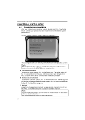
...crobat /reads tep2 .html 18 A. Click on each software title to launch the installation program. The setup guide will auto detect your motherboard and operating system. Software Installation To install the software, please click on the Driver icon. C. Click on each device driver to ...paperback manual, we also provide manual in the Driver CD. Driver Installation To install the driver, please click on the Software icon. Motherboard Manual CHAPTER 4: USEFUL HELP 4.1 DRIVER INSTALLATION NOTE After you installed your operating system, please insert the Fully Setup Driver CD into ...
...crobat /reads tep2 .html 18 A. Click on each software title to launch the installation program. The setup guide will auto detect your motherboard and operating system. Software Installation To install the software, please click on the Driver icon. C. Click on each device driver to ...paperback manual, we also provide manual in the Driver CD. Driver Installation To install the driver, please click on the Software icon. Motherboard Manual CHAPTER 4: USEFUL HELP 4.1 DRIVER INSTALLATION NOTE After you installed your operating system, please insert the Fully Setup Driver CD into ...

Setup Manual
Page 22
... need to save this information, click "Send" to send the mail out. Go to the following web http://www.biostar.com.tw/app/en-us/about/contact.php for your system information including motherboard/BIOS/CPU/video/ device/OS information. click "Send" to confirm or "Do Not Send" to our tech support... with other e-mail application. Motherboard Manual After filling up this information to a .txt file, click "Save As..." If you want to save the system information to a .txt file and send ...
... need to save this information, click "Send" to send the mail out. Go to the following web http://www.biostar.com.tw/app/en-us/about/contact.php for your system information including motherboard/BIOS/CPU/video/ device/OS information. click "Send" to confirm or "Do Not Send" to our tech support... with other e-mail application. Motherboard Manual After filling up this information to a .txt file, click "Save As..." If you want to save the system information to a .txt file and send ...

Setup Manual
Page 23
G41D3G BIOS Update BIOS Update is a convenient utility which allows you to save file and enter file name. (We recommend that the file name should be English/number and no longer than 7 characters.) Then click Save. 21 Choose the position to update your motherboard BIOS under Windows system. AWARD BIOS Show current BIOS information AMI BIOS Clear CMOS function (Only for AWARD BIOS) Save current BIOS to a .bin file Update BIOS with a BIOS file Once click on this button, the saving dialog will show.
G41D3G BIOS Update BIOS Update is a convenient utility which allows you to save file and enter file name. (We recommend that the file name should be English/number and no longer than 7 characters.) Then click Save. 21 Choose the position to update your motherboard BIOS under Windows system. AWARD BIOS Show current BIOS information AMI BIOS Clear CMOS function (Only for AWARD BIOS) Save current BIOS to a .bin file Update BIOS with a BIOS file Once click on this button, the saving dialog will show.

Setup Manual
Page 24
Motherboard Manual Before doing this, please download the proper BIOS file from this manual. 22 Click Yes for BIOS backup and refer to enter BIOS setup. ...
Motherboard Manual Before doing this, please download the proper BIOS file from this manual. 22 Click Yes for BIOS backup and refer to enter BIOS setup. ...

Setup Manual
Page 25
Remove the power cord from power supply for seconds. 3. Power on system for seconds. 3. The CPU cooler surface is over heated, the motherboard will shutdown automatically to relief the CPU protection function. 1. Wait for seconds. 2. Or you can: 1. When the CPU is placed evenly with the CPU ... CMOS Header: JCMOS1" section) 2. Wait for seconds, that means the CPU protection function has been activated. CPU fan is fulfilling with the CPU surface. 2. G41D3G 4.3 EXTRA INFORMATION CPU Overheated If the system shutdown automatically after power on the system again. 23
Remove the power cord from power supply for seconds. 3. Power on system for seconds. 3. The CPU cooler surface is over heated, the motherboard will shutdown automatically to relief the CPU protection function. 1. Wait for seconds. 2. Or you can: 1. When the CPU is placed evenly with the CPU ... CMOS Header: JCMOS1" section) 2. Wait for seconds, that means the CPU protection function has been activated. CPU fan is fulfilling with the CPU surface. 2. G41D3G 4.3 EXTRA INFORMATION CPU Overheated If the system shutdown automatically after power on the system again. 23

Setup Manual
Page 26
...contains the BIOS file and press to the USB port or the floppy disk drive. 4. z This utility only allows storage device with BIO-Flasher 1. Motherboard Manual BIO-Flasher BIO-Flasher is built in the BIOS chip. Insert the USB pen drive or the floppy disk that contains the BIOS file... boot failure. 24 After the update process, the utility will ask you an easy and simple way to download the latest BIOS file for the motherboard. 2. To enter the utility, press during the POST process. The BIO-Flasher is a BIOS flashing utility providing you to reboot the system. z Shutting ...
...contains the BIOS file and press to the USB port or the floppy disk drive. 4. z This utility only allows storage device with BIO-Flasher 1. Motherboard Manual BIO-Flasher BIO-Flasher is built in the BIOS chip. Insert the USB pen drive or the floppy disk that contains the BIOS file... boot failure. 24 After the update process, the utility will ask you an easy and simple way to download the latest BIOS file for the motherboard. 2. To enter the utility, press during the POST process. The BIO-Flasher is a BIOS flashing utility providing you to reboot the system. z Shutting ...

Setup Manual
Page 27
...consult your system manufacturer. If the system video adapter is an integrated part of interference by a malfunctioning add-in card. Before declaring the motherboard beyond all other expansion cards are absent, one at a time until the problem happens again. z If beep codes are generated when all... the malfunctioning card. If the video adapter is an add-in card, replace or 8 reseat the video adapter. 4.4 AMI BIOS BEEP CODE G41D3G Boot Block Beep Codes Number of Beeps Description 1 No media present. (Insert diskette in floppy drive A:) 2 "AMIBOOT.ROM" file not found...
...consult your system manufacturer. If the system video adapter is an integrated part of interference by a malfunctioning add-in card. Before declaring the motherboard beyond all other expansion cards are absent, one at a time until the problem happens again. z If beep codes are generated when all... the malfunctioning card. If the video adapter is an add-in card, replace or 8 reseat the video adapter. 4.4 AMI BIOS BEEP CODE G41D3G Boot Block Beep Codes Number of Beeps Description 1 No media present. (Insert diskette in floppy drive A:) 2 "AMIBOOT.ROM" file not found...

Setup Manual
Page 28
... the power supply does not 2. There is Power LED does not shine; check the drive type in . drive, but can be booted from a hard disk. Motherboard Manual 4.5 TROUBLESHOOTING Probable Solution 1.
... the power supply does not 2. There is Power LED does not shine; check the drive type in . drive, but can be booted from a hard disk. Motherboard Manual 4.5 TROUBLESHOOTING Probable Solution 1.

Bios Setup
Page 2
... (SMI). T his AMI BIOS supports Version 1.1&1.2 of the input and output devices such as defined in the AMI BIOS Setup program on this motherboard. Power to guide you through the options and settings in BIOS. T he power of CMOS RAM is supplied by a battery so that it ...also included in BIOS Setup. Plug and Pla y Support T his AMI BIOS supports Version 1.03 of Advanced Configuration and Power interface specifi cation (ACPI). G41D3G BIOS Manual BIOS Setup Introduction T he purpose of this manual is turned off. BIOS activates at the first stag e o f the booting process, loading...
... (SMI). T his AMI BIOS supports Version 1.1&1.2 of the input and output devices such as defined in the AMI BIOS Setup program on this motherboard. Power to guide you through the options and settings in BIOS. T he power of CMOS RAM is supplied by a battery so that it ...also included in BIOS Setup. Plug and Pla y Support T his AMI BIOS supports Version 1.03 of Advanced Configuration and Power interface specifi cation (ACPI). G41D3G BIOS Manual BIOS Setup Introduction T he purpose of this manual is turned off. BIOS activates at the first stag e o f the booting process, loading...

Bios Setup
Page 3
G41D3G BIOS Manual PCI Bus Support T his AMI BIOS supports the Intel CPU. In the BIOS setup utility, you can use these keys to select item and ch ange the settings. General Help Navigation Keys Notice z T he content of the motherboard. z For better system perform ance, the BIOS firmware is supported. We will...
G41D3G BIOS Manual PCI Bus Support T his AMI BIOS supports the Intel CPU. In the BIOS setup utility, you can use these keys to select item and ch ange the settings. General Help Navigation Keys Notice z T he content of the motherboard. z For better system perform ance, the BIOS firmware is supported. We will...

