
Setup Manual
Page 2
Table of Contents Chapter 1: Introduction 1 1.1 Before You Start 1 1.2 Package Checklist 1 1.3 Motherboard Features 2 1.4 Rear Panel Connectors 3 1.5 Motherboard Layout 4 Chapter 2: Hardware Installation 5 2.1 Installing Central Processing Unit (CPU 5 2.2 FAN Headers 7 2.3 Installing System Memory 8 2.4 Connectors and Slots 10 Chapter 3: Headers & Jumpers Setup 13 3.1 How to ...
Table of Contents Chapter 1: Introduction 1 1.1 Before You Start 1 1.2 Package Checklist 1 1.3 Motherboard Features 2 1.4 Rear Panel Connectors 3 1.5 Motherboard Layout 4 Chapter 2: Hardware Installation 5 2.1 Installing Central Processing Unit (CPU 5 2.2 FAN Headers 7 2.3 Installing System Memory 8 2.4 Connectors and Slots 10 Chapter 3: Headers & Jumpers Setup 13 3.1 How to ...
Setup Manual
Page 3
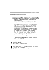
...to 45 degrees Celsius. 1.2 PACKAGE CHECKLIST Serial ATA Cable X 2 Rear I/O Panel for choosing our product. Before you start installing the motherboard, please make sure you follow the instructions below: „ Prepare a dry and stable working environment with sufficient lighting. „ Always ... the rear side of the computer should be different due to area or your motherboard version. 1 CHAPTER 1: INTRODUCTION A880GU3Z/A880GZ 1.1 BEFORE YOU START Thank you take the motherboard out from anti-static bag, ground yourself properly by touching any unfastened small parts inside ) USB 2.0 ...
...to 45 degrees Celsius. 1.2 PACKAGE CHECKLIST Serial ATA Cable X 2 Rear I/O Panel for choosing our product. Before you start installing the motherboard, please make sure you follow the instructions below: „ Prepare a dry and stable working environment with sufficient lighting. „ Always ... the rear side of the computer should be different due to area or your motherboard version. 1 CHAPTER 1: INTRODUCTION A880GU3Z/A880GZ 1.1 BEFORE YOU START Thank you take the motherboard out from anti-static bag, ground yourself properly by touching any unfastened small parts inside ) USB 2.0 ...

Setup Manual
Page 4
Motherboard Manual 1.3 MOTHERBOARD FEATURES CPU FSB Chipset A880GU3Z A880GZ Socket AM3+ Socket AM3+ AMD Sempron/Athlon II/Phenom II/FX AMD Sempron/Athlon II/Phenom II/FX processors ...
Motherboard Manual 1.3 MOTHERBOARD FEATURES CPU FSB Chipset A880GU3Z A880GZ Socket AM3+ Socket AM3+ AMD Sempron/Athlon II/Phenom II/FX AMD Sempron/Athlon II/Phenom II/FX processors ...
Setup Manual
Page 6
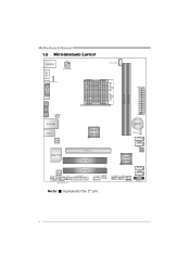
Motherboard Manual 1.5 MOTHERBOARD LAYOUT USBKBMS1 ATX PW R 2 HDM I1 JUSBV1 C PU _FAN 1 ATXPW R1 Socket AM3+ DVI1 D DR 3_ A 1 D D R 3_ B1 VGA1 JU SBV3 R J45U SB1 A UDI O1 LAN Super I/O AMD 880G P E X16_1 PCI1 BAT1 J C MO S1 AMD SB850 SATA4 SATA3 BIOS Codec CIR 1 F_ AUD IO1 JSP DI FO UT1 PCI2 J_PR IN T1 SATA2 J_COM 1 J US BV 2 F_USB1 F_USB2 SYS_FAN1 SATA1 PA NE L1 Note: ■ represents the 1st pin. 4
Motherboard Manual 1.5 MOTHERBOARD LAYOUT USBKBMS1 ATX PW R 2 HDM I1 JUSBV1 C PU _FAN 1 ATXPW R1 Socket AM3+ DVI1 D DR 3_ A 1 D D R 3_ B1 VGA1 JU SBV3 R J45U SB1 A UDI O1 LAN Super I/O AMD 880G P E X16_1 PCI1 BAT1 J C MO S1 AMD SB850 SATA4 SATA3 BIOS Codec CIR 1 F_ AUD IO1 JSP DI FO UT1 PCI2 J_PR IN T1 SATA2 J_COM 1 J US BV 2 F_USB1 F_USB2 SYS_FAN1 SATA1 PA NE L1 Note: ■ represents the 1st pin. 4
Setup Manual
Page 8
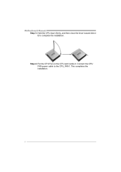
Connect the CPU FAN power cable to complete the installation. Motherboard Manual Step 3: Hold the CPU down firmly, and then close the lever toward direct B to the CPU_FAN1. This completes the installation. 6 Step 4: Put the CPU Fan on the CPU and buckle it.
Connect the CPU FAN power cable to complete the installation. Motherboard Manual Step 3: Hold the CPU down firmly, and then close the lever toward direct B to the CPU_FAN1. This completes the installation. 6 Step 4: Put the CPU Fan on the CPU and buckle it.

Setup Manual
Page 10
DDR3_A 1 DDR3_B 1 Motherboard Manual 2.3 INSTALLING SYSTEM MEMORY A. Unlock a DIMM slot by pressing the retaining clips outward. Insert the DIMM vertically and firmly into the slot until the retaining chip snap back in place and the DIMM is properly seated. 8 Align a DIMM on the slot such that the notch on the DIMM matches the break on the Slot. 2. Memory Modules 1.
DDR3_A 1 DDR3_B 1 Motherboard Manual 2.3 INSTALLING SYSTEM MEMORY A. Unlock a DIMM slot by pressing the retaining clips outward. Insert the DIMM vertically and firmly into the slot until the retaining chip snap back in place and the DIMM is properly seated. 8 Align a DIMM on the slot such that the notch on the DIMM matches the break on the Slot. 2. Memory Modules 1.

Setup Manual
Page 12
SA TA4 SA TA3 SA TA2 SA TA1 74 1 Pin Assignment 1 Ground 2 TX+ 3 TX4 Ground 5 RX6 RX+ 7 Ground ATXPWR2: ATX Power Source Connector This connector will provide +12V to SATA Controller with 4 channels SATA interface, it satisfies the SATA 2.0 spec and with transfer rate of 3.0Gb/s. Motherboard Manual 2.4 CONNECTORS AND SLOTS SATA1~SATA4: Serial ATA Connectors The motherboard has a PCI to CPU power circuit. 21 34 Pin Assignment 1 +12V 2 +12V 3 Ground 4 Ground 10
SA TA4 SA TA3 SA TA2 SA TA1 74 1 Pin Assignment 1 Ground 2 TX+ 3 TX4 Ground 5 RX6 RX+ 7 Ground ATXPWR2: ATX Power Source Connector This connector will provide +12V to SATA Controller with 4 channels SATA interface, it satisfies the SATA 2.0 spec and with transfer rate of 3.0Gb/s. Motherboard Manual 2.4 CONNECTORS AND SLOTS SATA1~SATA4: Serial ATA Connectors The motherboard has a PCI to CPU power circuit. 21 34 Pin Assignment 1 +12V 2 +12V 3 Ground 4 Ground 10

Setup Manual
Page 14
This PCI slot is equipped with 2 standard PCI slots. PCI1 PCI2 12 Motherboard Manual PEX16_1: PCI-Express Gen2 x16 Slot - PCI stands for Peripheral Component Interconnect, and it is a bus standard for an aggregate of 8GB/s simultaneously per direction, for expansion cards. Maximum theoretical realized bandwidth of 16GB/s totally. PEX16 _1 PCI1~PCI2: Peripheral Component Interconnect Slots This motherboard is designated as 32 bits. PCI-Express 2.0 compliant. -
This PCI slot is equipped with 2 standard PCI slots. PCI1 PCI2 12 Motherboard Manual PEX16_1: PCI-Express Gen2 x16 Slot - PCI stands for Peripheral Component Interconnect, and it is a bus standard for an aggregate of 8GB/s simultaneously per direction, for expansion cards. Maximum theoretical realized bandwidth of 16GB/s totally. PEX16 _1 PCI1~PCI2: Peripheral Component Interconnect Slots This motherboard is designated as 32 bits. PCI-Express 2.0 compliant. -

Setup Manual
Page 16
... allows user to connect additional USB cable on the PC front panel, and also can be connected with internal USB devices, like USB card reader. Motherboard Manual F_USB1/F_USB2: Headers for USB 2.0 Ports at F_USB1/F_USB2.
... allows user to connect additional USB cable on the PC front panel, and also can be connected with internal USB devices, like USB card reader. Motherboard Manual F_USB1/F_USB2: Headers for USB 2.0 Ports at F_USB1/F_USB2.
Setup Manual
Page 18
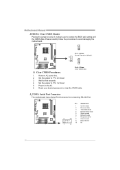
... carefully follow the procedures to restore the BIOS safe setting and the CMOS data. Power on pin2-3, it allows user to avoid damaging the motherboard. 3 1 Pin 1-2 Close: Normal Operation (default). 3 1 3 1 Pin 2-3 Close: Clear CMOS data. ※ Clear CMOS Procedures: 1. Reset ...your desired password or clear the CMOS data. Motherboard Manual JCMOS1: Clear CMOS Header Placing the jumper on the AC. 6. Remove AC power line. 2. Set the jumper to "Pin 1-2 close ". 3. J_COM1: Serial Port Connector The motherboard has a Serial Port Connector for five seconds. 4.
... carefully follow the procedures to restore the BIOS safe setting and the CMOS data. Power on pin2-3, it allows user to avoid damaging the motherboard. 3 1 Pin 1-2 Close: Normal Operation (default). 3 1 3 1 Pin 2-3 Close: Clear CMOS data. ※ Clear CMOS Procedures: 1. Reset ...your desired password or clear the CMOS data. Motherboard Manual JCMOS1: Clear CMOS Header Placing the jumper on the AC. 6. Remove AC power line. 2. Set the jumper to "Pin 1-2 close ". 3. J_COM1: Serial Port Connector The motherboard has a Serial Port Connector for five seconds. 4.

Setup Manual
Page 20
... fault tolerance. Block 1 Block 3 Block 5 18 Block 2 Block 4 Block 6 It breaks up to 6 or 8. This technique reduces overall disk access time and offers high bandwidth. Motherboard Manual CHAPTER 4: RAID FUNCTIONS 4.1 OPERATING SYSTEM Supports Windows XP, Windows Vista, and Windows 7. 4.2 RAID ARRAYS RAID supports the following types of RAID arrays: RAID 0: RAID...
... fault tolerance. Block 1 Block 3 Block 5 18 Block 2 Block 4 Block 6 It breaks up to 6 or 8. This technique reduces overall disk access time and offers high bandwidth. Motherboard Manual CHAPTER 4: RAID FUNCTIONS 4.1 OPERATING SYSTEM Supports Windows XP, Windows Vista, and Windows 7. 4.2 RAID ARRAYS RAID supports the following types of RAID arrays: RAID 0: RAID...

Setup Manual
Page 22
Drives: Minimum 4, and maximum is 6 or 8, depending on the platform. - Drawbacks: Requires twice the available disk space for spare disks. - Fault Tolerance: Yes. Motherboard Manual RAID 10: RAID 1 drives can be simultaneously used with other RAID levels in a RAID 10 solution for automatic redundancy. May be stripped using RAID 0 ...
Drives: Minimum 4, and maximum is 6 or 8, depending on the platform. - Drawbacks: Requires twice the available disk space for spare disks. - Fault Tolerance: Yes. Motherboard Manual RAID 10: RAID 1 drives can be simultaneously used with other RAID levels in a RAID 10 solution for automatic redundancy. May be stripped using RAID 0 ...

Setup Manual
Page 24
A. Manual Aside from http://www.adobe.com /produ cts/a crobat /reads tep2 .html 22 Note: You will auto detect your motherboard and operating system. Motherboard Manual CHAPTER 5: USEFUL HELP 5.1 DRIVER INSTALLATION NOTE After you installed your operating system, please insert the Fully Setup Driver CD into... didn't show up after you insert the Driver CD, please use file browser to locate and execute the file SETUP.EXE under your motherboard and operating system. Click on each software title to open the manual file. Please download the latest version of Acrobat Reader software from...
A. Manual Aside from http://www.adobe.com /produ cts/a crobat /reads tep2 .html 22 Note: You will auto detect your motherboard and operating system. Motherboard Manual CHAPTER 5: USEFUL HELP 5.1 DRIVER INSTALLATION NOTE After you installed your operating system, please insert the Fully Setup Driver CD into... didn't show up after you insert the Driver CD, please use file browser to locate and execute the file SETUP.EXE under your motherboard and operating system. Click on each software title to open the manual file. Please download the latest version of Acrobat Reader software from...

Setup Manual
Page 26
.... Open the saved .txt file, you to the following web http://www.biostar.com.tw/app/en-us/about/contact.php for your system information while using Outlook Express as your system information including motherboard/BIOS/CPU/video/ device/OS information. Motherboard Manual After filling up this information to a .txt file, click "Save...
.... Open the saved .txt file, you to the following web http://www.biostar.com.tw/app/en-us/about/contact.php for your system information while using Outlook Express as your system information including motherboard/BIOS/CPU/video/ device/OS information. Motherboard Manual After filling up this information to a .txt file, click "Save...

Setup Manual
Page 27
Choose the position to a .bin file Update BIOS with a BIOS file Once click on this button, the saving dialog will show. AWARD BIOS Show current BIOS information AMI BIOS Clear CMOS function (Only for AWARD BIOS) Save current BIOS to save file and enter file name. (We recommend that the file name should be English/number and no longer than 7 characters.) Then click Save. 25 A880GU3Z/A880GZ BIOS Update BIOS Update is a convenient utility which allows you to update your motherboard BIOS under Windows system.
Choose the position to a .bin file Update BIOS with a BIOS file Once click on this button, the saving dialog will show. AWARD BIOS Show current BIOS information AMI BIOS Clear CMOS function (Only for AWARD BIOS) Save current BIOS to save file and enter file name. (We recommend that the file name should be English/number and no longer than 7 characters.) Then click Save. 25 A880GU3Z/A880GZ BIOS Update BIOS Update is a convenient utility which allows you to update your motherboard BIOS under Windows system.

Setup Manual
Page 28
... procedure. All the information and content above are subject to restart the system. Please choose the proper BIOS file for asking you backup current BIOS. Motherboard Manual Before doing this process may be run with the proper BIOS file, and this , please download the proper BIOS file from this manual. 26...
... procedure. All the information and content above are subject to restart the system. Please choose the proper BIOS file for asking you backup current BIOS. Motherboard Manual Before doing this process may be run with the proper BIOS file, and this , please download the proper BIOS file from this manual. 26...

Setup Manual
Page 29
... can: 1. A880GU3Z/A880GZ 5.3 EXTRA INFORMATION CPU Overheated If the system shutdown automatically after power on system for seconds. 3. CPU fan speed is over heated, the motherboard will shutdown automatically to relief the CPU protection function. 1.
... can: 1. A880GU3Z/A880GZ 5.3 EXTRA INFORMATION CPU Overheated If the system shutdown automatically after power on system for seconds. 3. CPU fan speed is over heated, the motherboard will shutdown automatically to relief the CPU protection function. 1.

Setup Manual
Page 30
... as the picture on or reset the computer and then press during the Power-On Self Tests (POST) procedure while booting up. BIOS update completes. Motherboard Manual BIO-Flasher BIO-Flasher is built in the BIOS chip. To enter the utility, press during the POST process. Insert the USB pen drive... updating the BIOS will lead to proceed. The utility will ask you an easy and simple way to download the latest BIOS file for the motherboard. 2. Then, save the BIOS file into a USB pen drive or a floppy disk. 3. Select the proper BIOS file and press then to reboot the system. After...
... as the picture on or reset the computer and then press during the Power-On Self Tests (POST) procedure while booting up. BIOS update completes. Motherboard Manual BIO-Flasher BIO-Flasher is built in the BIOS chip. To enter the utility, press during the POST process. Insert the USB pen drive... updating the BIOS will lead to proceed. The utility will ask you an easy and simple way to download the latest BIOS file for the motherboard. 2. Then, save the BIOS file into a USB pen drive or a floppy disk. 3. Select the proper BIOS file and press then to reboot the system. After...

Setup Manual
Page 31
... at a time until the problem happens again. If the video adapter is an integrated part of interference by a malfunctioning add-in card. Before declaring the motherboard beyond all other expansion cards are absent, consult your system manufacturer. 5.4 AMI BIOS BEEP CODE A880GU3Z/A880GZ Boot Block Beep Codes Number of Beeps Description...
... at a time until the problem happens again. If the video adapter is an integrated part of interference by a malfunctioning add-in card. Before declaring the motherboard beyond all other expansion cards are absent, consult your system manufacturer. 5.4 AMI BIOS BEEP CODE A880GU3Z/A880GZ Boot Block Beep Codes Number of Beeps Description...
Setup Manual
Page 32
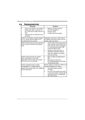
.... System does not boot from a hard disk. All hard disks are running from disk to boot from a hard disk 1. System cannot boot after user installs a 1. Motherboard Manual 5.5 TROUBLESHOOTING Probable Solution 1. module snaps into place. Make sure both ends of are on keyboard does not shine. Call the drive manufacturers for compatibility...
.... System does not boot from a hard disk. All hard disks are running from disk to boot from a hard disk 1. System cannot boot after user installs a 1. Motherboard Manual 5.5 TROUBLESHOOTING Probable Solution 1. module snaps into place. Make sure both ends of are on keyboard does not shine. Call the drive manufacturers for compatibility...


