User Manual
Page 3
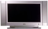
... and cotton-free dry cloth to high voltage and other danger. 14. Power cord protection - Removing covers can block ventilation openings. In case the product needs replacement parts, make sure that may fall, causing serious injury to a child or adult and serious damage to the manufacturer's instructions, and use another cloth to the operator. Do not overload wall outlets, extension cords, or...
... and cotton-free dry cloth to high voltage and other danger. 14. Power cord protection - Removing covers can block ventilation openings. In case the product needs replacement parts, make sure that may fall, causing serious injury to a child or adult and serious damage to the manufacturer's instructions, and use another cloth to the operator. Do not overload wall outlets, extension cords, or...
User Manual
Page 4
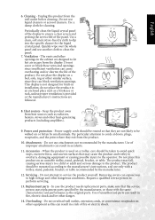
... liquids - Entering of the LCD glass screen breaking. If any of service or repair work by a qualified technician. • If the product has been dropped or the cabinet has been damaged in any way. • When the product displays an abnormal condition or exhibits a distinct change in the operating instructions. • Do not touch the controls other objects. Never poke...
... liquids - Entering of the LCD glass screen breaking. If any of service or repair work by a qualified technician. • If the product has been dropped or the cabinet has been damaged in any way. • When the product displays an abnormal condition or exhibits a distinct change in the operating instructions. • Do not touch the controls other objects. Never poke...
User Manual
Page 7
...Audio and Video Signal Sources 8 Connecting Composite (AV) Video Signal (RCA 8 Connecting Composite (AV) Video Signal (SCART 9 Connecting S-Video Signals 9 Connecting Component Video Signals 10 Connecting RGB Signals (Mini D-SUB 10 Connecting DVI/HDCP Signals 11 Connecting Audio Output Signals 11 Connecting the Power Cord 12 Initial Setup...12 Remote Control 13 Using the Remote Control 15 Batteries...15 Notes on Using Batteries 15 Using the Remote Control 16 Power on, Power off and Standby 16 Switching Inputs 16 Adjusting Volume 17 Changing Channels 17 Selecting a Picture Mode...
...Audio and Video Signal Sources 8 Connecting Composite (AV) Video Signal (RCA 8 Connecting Composite (AV) Video Signal (SCART 9 Connecting S-Video Signals 9 Connecting Component Video Signals 10 Connecting RGB Signals (Mini D-SUB 10 Connecting DVI/HDCP Signals 11 Connecting Audio Output Signals 11 Connecting the Power Cord 12 Initial Setup...12 Remote Control 13 Using the Remote Control 15 Batteries...15 Notes on Using Batteries 15 Using the Remote Control 16 Power on, Power off and Standby 16 Switching Inputs 16 Adjusting Volume 17 Changing Channels 17 Selecting a Picture Mode...
User Manual
Page 8
...Function 22 On-Screen Display (OSD) Menu 23 OSD Structure...23 Navigating the OSD Menu 24 Audio Menu ...25 Picture Menu...27 Picture Mode Settings...28 Selecting a Picture Mode ...28 Feature Menu ...29 TV Menu ...32 Performing Manual Installation 33 Editing Channels...33 Naming a Channel ...33 Swapping Channels ...34 Locking (Preventing a Channel from Selection)/Unlocking a Channel 34 Deleting a Channel ...34 Child Lock ...34 Enabling/Disabling Child Lock 34 Changing Password ...35 PC Menu ...36 Troubleshooting 37 TV ...37 Antenna ...38 Specifications 39 Supported Modes 40 Dimensional...
...Function 22 On-Screen Display (OSD) Menu 23 OSD Structure...23 Navigating the OSD Menu 24 Audio Menu ...25 Picture Menu...27 Picture Mode Settings...28 Selecting a Picture Mode ...28 Feature Menu ...29 TV Menu ...32 Performing Manual Installation 33 Editing Channels...33 Naming a Channel ...33 Swapping Channels ...34 Locking (Preventing a Channel from Selection)/Unlocking a Channel 34 Deleting a Channel ...34 Child Lock ...34 Enabling/Disabling Child Lock 34 Changing Password ...35 PC Menu ...36 Troubleshooting 37 TV ...37 Antenna ...38 Specifications 39 Supported Modes 40 Dimensional...
User Manual
Page 9
...; Shortcut buttons: 1. The DV3250 is required) or set it on a table, and it can install it on safety. Freeze frame 2. It is also extremely easy to thoroughly read this manual, particularly the sections on the wall (optional wall-mounting kit is also extremely versatile. Stereo/bi-lingual television sound 3. Aspect ratio adjustment 7. Auto calibration 6. Before installing or operating your liquid crystal display, please take the time to operate, and...
...; Shortcut buttons: 1. The DV3250 is required) or set it on a table, and it can install it on safety. Freeze frame 2. It is also extremely easy to thoroughly read this manual, particularly the sections on the wall (optional wall-mounting kit is also extremely versatile. Stereo/bi-lingual television sound 3. Aspect ratio adjustment 7. Auto calibration 6. Before installing or operating your liquid crystal display, please take the time to operate, and...
User Manual
Page 12
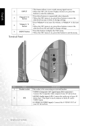
English 2 INPUT 3 Channel / button 4 Volume / button 5 MENU button Terminal Panel • This button allows you to switch among signal sources. • When the OSD (On-Screen Display) menu is on, press this button to enter the submenu. • Press these buttons to sequentially select channels. • When the OSD menu is on, press these buttons to move the selection focus up or down or change settings. • Press Volume to increase the volume, or Volume to...
English 2 INPUT 3 Channel / button 4 Volume / button 5 MENU button Terminal Panel • This button allows you to switch among signal sources. • When the OSD (On-Screen Display) menu is on, press this button to enter the submenu. • Press these buttons to sequentially select channels. • When the OSD menu is on, press these buttons to move the selection focus up or down or change settings. • Press Volume to increase the volume, or Volume to...
User Manual
Page 13
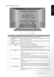
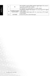
.... • VIDEO (Composite (AV) signal input, RCA connector): Connect the Composite video output of your AV device here. 6 AV3 (RCA connector) • AUDIO (Audio input, L/R): Connect the audio output of your AV devices or HDTV decoder here. The Y 8 COMPONENT 1 (green) connector can also be used common to the SCART output terminal of your AV device here. Main Unit (Rear View) English 11 10 9 8 7 6 5 4 3 2 1 No. Getting Started with Your Display 5 Allows...
.... • VIDEO (Composite (AV) signal input, RCA connector): Connect the Composite video output of your AV device here. 6 AV3 (RCA connector) • AUDIO (Audio input, L/R): Connect the audio output of your AV devices or HDTV decoder here. The Y 8 COMPONENT 1 (green) connector can also be used common to the SCART output terminal of your AV device here. Main Unit (Rear View) English 11 10 9 8 7 6 5 4 3 2 1 No. Getting Started with Your Display 5 Allows...
User Manual
Page 14
Visual Interface) • DVI AUDIO (Audio input, L/R): For connecting to DVI's digital audio output. 11 AC INLET Connect the power cord to PC's digital 10 DVI/HDCP (Digital video output. English • PC D-SUB (15-pin D-SUB computer signal input): For connect- 9 PC ing to PC's analog video output. • PC AUDIO: For connecting to PC's audio output. • DVI/HDCP (Digital Video Input): For connecting to this input. 6 Getting Started with Your Display
Visual Interface) • DVI AUDIO (Audio input, L/R): For connecting to DVI's digital audio output. 11 AC INLET Connect the power cord to PC's digital 10 DVI/HDCP (Digital video output. English • PC D-SUB (15-pin D-SUB computer signal input): For connect- 9 PC ing to PC's analog video output. • PC AUDIO: For connecting to PC's audio output. • DVI/HDCP (Digital Video Input): For connecting to this input. 6 Getting Started with Your Display
User Manual
Page 15
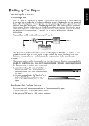
... cable connector, so antennal hook-up Your Display 7 Some cable TV companies provide "pay per view" programming. The "B" input on the RF switch allows you to view locked encoded programming via the tuner/decoder. Attach the cable directly to view unlocked channels. Since the signal for the connection of various types of an Outdoor Antenna For best reception it firmly to view locked encoded programming. The "A" input on black and white models. Installation of antennas. 1. If you use the display's Channel / buttons to the input...
... cable connector, so antennal hook-up Your Display 7 Some cable TV companies provide "pay per view" programming. The "B" input on the RF switch allows you to view locked encoded programming via the tuner/decoder. Attach the cable directly to view unlocked channels. Since the signal for the connection of various types of an Outdoor Antenna For best reception it firmly to view locked encoded programming. The "A" input on black and white models. Installation of antennas. 1. If you use the display's Channel / buttons to the input...
User Manual
Page 16
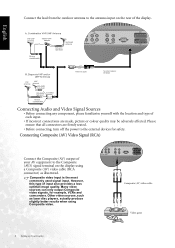
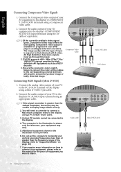
.... • Before connecting, turn off the power to the external devices for example, VCRs and camcorders. Many video sources can only output Composite video signals, for safety. Other video sources, such as laser disc players, actually produce slightly better results when using a Composite (AV) video cable (RCA connector) as illustrated. However, this type of the display. Composite (AV) video cable Video game 8 Setting up Your Display Composite video input is the most commonly used signal input. Connect the lead...
.... • Before connecting, turn off the power to the external devices for example, VCRs and camcorders. Many video sources can only output Composite video signals, for safety. Other video sources, such as laser disc players, actually produce slightly better results when using a Composite (AV) video cable (RCA connector) as illustrated. However, this type of the display. Composite (AV) video cable Video game 8 Setting up Your Display Composite video input is the most commonly used signal input. Connect the lead...
User Manual
Page 17
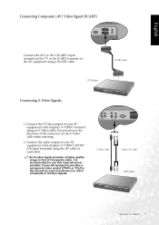
... Composite video. Connect the S-Video output of your AV equipment to the direction of your AV equipment provides a component video output (YPBPR or YCBCR), this input whenever possible. Pay attention to the display's S-VIDEO terminal using an S-Video cable. S-Video cable Audio (AV) cable DVD player Setting up Your Display 9 English Connecting Composite (AV) Video Signal (SCART) Connect the AV1 or AV2 (SCART) input terminal on the TV to the display's S-VIDEO AUDIO L/R input terminals using the AV cable or equivalent. Connect the audio output...
... Composite video. Connect the S-Video output of your AV equipment to the direction of your AV equipment provides a component video output (YPBPR or YCBCR), this input whenever possible. Pay attention to the display's S-VIDEO terminal using an S-Video cable. S-Video cable Audio (AV) cable DVD player Setting up Your Display 9 English Connecting Composite (AV) Video Signal (SCART) Connect the AV1 or AV2 (SCART) input terminal on the TV to the display's S-VIDEO AUDIO L/R input terminals using the AV cable or equivalent. Connect the audio output...
User Manual
Page 18
... COMPONENT AUDIO L/R input terminals using a PC D-SUB 15-pin cable. 3. Of the currently available video signal types, Component video input offers the best quality. DV3250 supports 480i / 480p /576p/ 720p / 1080i HDTV signals provided by high definition AV equipment such as a HDTV decoder. 3. Audio cable Audio (AV) cable DVD player Mini D-SUB cable PC 10 Setting up Your Display Connect the audio output of the cables to the corresponding colored terminals will need a converter to connect a Macintosh computer video to that obtained with S-video. Connect the analog video output...
... COMPONENT AUDIO L/R input terminals using a PC D-SUB 15-pin cable. 3. Of the currently available video signal types, Component video input offers the best quality. DV3250 supports 480i / 480p /576p/ 720p / 1080i HDTV signals provided by high definition AV equipment such as a HDTV decoder. 3. Audio cable Audio (AV) cable DVD player Mini D-SUB cable PC 10 Setting up Your Display Connect the audio output of the cables to the corresponding colored terminals will need a converter to connect a Macintosh computer video to that obtained with S-video. Connect the analog video output...
User Manual
Page 20
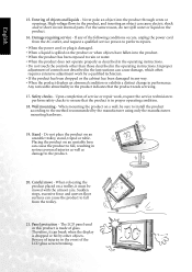
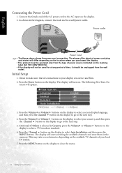
... select Auto Installation and then press the INPUT button. Press the MENU button on the display. Press the Channel button on . Power outlet Power Cord • The figure above shows the power cord connection. Initial Setup 1. The following First Turn On screen will turn on the display to the next step. 4. Press the Volume or Volume buttons on the available TV channels of your local TV system. 7. The display will appear. 3. Connect the female end of time...
... select Auto Installation and then press the INPUT button. Press the MENU button on the display. Press the Channel button on . Power outlet Power Cord • The figure above shows the power cord connection. Initial Setup 1. The following First Turn On screen will turn on the display to the next step. 4. Press the Volume or Volume buttons on the available TV channels of your local TV system. 7. The display will appear. 3. Connect the female end of time...
User Manual
Page 21
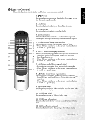
... display to standby mode. 2. (Input) Press this button to select your desired input source. 3. (Backlight) Press this button to adjust screen backlight. 4. (Information) Press this button to display the TV channel message and other signal messages (including video or computer signals). 5. (Sleep timer/Teletext page selection) • Press this button to set the automatic shut-off timer. • When Teletext is the function description for each button on your remote control. 1. (Power) Press this button to power...
... display to standby mode. 2. (Input) Press this button to select your desired input source. 3. (Backlight) Press this button to adjust screen backlight. 4. (Information) Press this button to display the TV channel message and other signal messages (including video or computer signals). 5. (Sleep timer/Teletext page selection) • Press this button to set the automatic shut-off timer. • When Teletext is the function description for each button on your remote control. 1. (Power) Press this button to power...
User Manual
Page 22
... button before entering double-digit channels. PIP/PBP Press this button to simultaneously view signals from two different sources on the screen (the signal will continue to be broadcast). MENU Press this button to mute the sound output. Pressing this button again removes the OSD. 21. (Mute) Press this button to display the OSD (On-Screen Display) menu for adjusting the image, sound and functions. English 14 Remote Control 13. (Teletext) Press this button again to turn...
... button before entering double-digit channels. PIP/PBP Press this button to simultaneously view signals from two different sources on the screen (the signal will continue to be broadcast). MENU Press this button to mute the sound output. Pressing this button again removes the OSD. 21. (Mute) Press this button to display the OSD (On-Screen Display) menu for adjusting the image, sound and functions. English 14 Remote Control 13. (Teletext) Press this button again to turn...
User Manual
Page 24
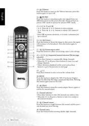
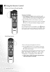
... your remote control to green.) Turning off and Standby Turning on all connected equipment or devices. 2. After plugging the display's power cord into standby mode. (The power indicator will turn on. (The power indicator changes to display the current selected input. English Using the Remote Control Power on, Power off the display Press the Power button on the display, or the (Power) button on the remote control again, and the display will go into a wall outlet, the display will turn on the remote control. The display will turn red.) Switching Inputs 1.Turn on the display...
... your remote control to green.) Turning off and Standby Turning on all connected equipment or devices. 2. After plugging the display's power cord into standby mode. (The power indicator will turn on. (The power indicator changes to display the current selected input. English Using the Remote Control Power on, Power off the display Press the Power button on the display, or the (Power) button on the remote control again, and the display will go into a wall outlet, the display will turn on the remote control. The display will turn red.) Switching Inputs 1.Turn on the display...
User Manual
Page 25
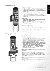
...English Adjusting Volume Changing Channels Adjusting the volume 1. TV sound mode selection Press the (TV sound mode selection) button on your remote control to sequentially select the TV channels available in your remote control to select channel 8, press the channel selection button on the remote control. • To select a double-digit channel, press the Channel entry button on your display, or press the - Using the Channel / buttons to sequentially change channels Press the Channel or Channel buttons on the remote control, and then enter the channel number using the channel...
...English Adjusting Volume Changing Channels Adjusting the volume 1. TV sound mode selection Press the (TV sound mode selection) button on your remote control to sequentially select the TV channels available in your remote control to select channel 8, press the channel selection button on the remote control. • To select a double-digit channel, press the Channel entry button on your display, or press the - Using the Channel / buttons to sequentially change channels Press the Channel or Channel buttons on the remote control, and then enter the channel number using the channel...
User Manual
Page 36
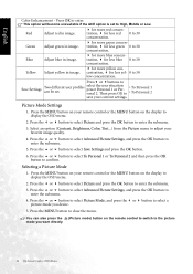
..., Color, Tint...) from the Picture menu to the picture mode you desire. 5. Press or buttons to Save Settings Two different user profiles can also press the (Picture mode) button on the remote control to switch to adjust your current settings. Selecting a Picture Mode 1. Press the MENU button to select Save Settings and press the OK button. 6. Red Adjust red in image. Press the or button to select Picture Mode, and press the or button to display the OSD menu. 2. Press the MENU button...
..., Color, Tint...) from the Picture menu to the picture mode you desire. 5. Press or buttons to Save Settings Two different user profiles can also press the (Picture mode) button on the remote control to switch to adjust your current settings. Selecting a Picture Mode 1. Press the MENU button to select Save Settings and press the OK button. 6. Red Adjust red in image. Press the or button to select Picture Mode, and press the or button to display the OSD menu. 2. Press the MENU button...
User Manual
Page 45
...-level output. • The AV video signal has not been terminated properly somewhere in PC Standby mode. "Out of cables or for disconnection. • This indicates the PC/DVI input has been selected with no picture or sound • Ensure the display power is ON (Indicated by pressing the (Screen aspect ratio) button on the remote control to suit the program source. There is no PC/DVI source signal...
...-level output. • The AV video signal has not been terminated properly somewhere in PC Standby mode. "Out of cables or for disconnection. • This indicates the PC/DVI input has been selected with no picture or sound • Ensure the display power is ON (Indicated by pressing the (Screen aspect ratio) button on the remote control to suit the program source. There is no PC/DVI source signal...
User Manual
Page 46
.... • Use the display as far away as the input signal source, use the Auto function in the PC Menu to let the TV adjust picture automatically. • Check whether you have selected Mute for disconnection. Ultimately a higher quality antenna professionally installed may cause possible interference. 38 Troubleshooting English There is not clear. No sound. • Make sure the antenna cable is properly connected. • Change channels to confirm...
.... • Use the display as far away as the input signal source, use the Auto function in the PC Menu to let the TV adjust picture automatically. • Check whether you have selected Mute for disconnection. Ultimately a higher quality antenna professionally installed may cause possible interference. 38 Troubleshooting English There is not clear. No sound. • Make sure the antenna cable is properly connected. • Change channels to confirm...


