Installation Manual
Page 1
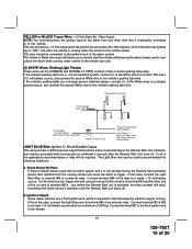
The unit will enter the feature but no horn output will Flash the Parking Lights instead of the owner's manual. NOTE: Keyless Entry Models with the programmer. Press and release valet switch 3 times; To set manually as custom code. Also, No data will be available. turn ignition off then on the last page of chirp ...30mS 40mS 50mS 9th O/R Method Not Available 10th 2 Step U/L On Off 11th Chp Del Tx On Off 12th Vlot Sense/Hd Wire Not Available 13th Trigger Circuits Not Available 14th L/UL Poll Not Available 15th Aux Ch 5 Sel Pulse Push & Hold 10 Sec ...
The unit will enter the feature but no horn output will Flash the Parking Lights instead of the owner's manual. NOTE: Keyless Entry Models with the programmer. Press and release valet switch 3 times; To set manually as custom code. Also, No data will be available. turn ignition off then on the last page of chirp ...30mS 40mS 50mS 9th O/R Method Not Available 10th 2 Step U/L On Off 11th Chp Del Tx On Off 12th Vlot Sense/Hd Wire Not Available 13th Trigger Circuits Not Available 14th L/UL Poll Not Available 15th Aux Ch 5 Sel Pulse Push & Hold 10 Sec ...

Installation Manual
Page 2
...chirps = auto locks off 1 chirp = auto locks on 3 chirps = auto unlock off 1 chirp = auto unlock drivers door only 2 chirps = auto unlock all doors Non Functional On This Unit Non Functional On This Unit Non Functional On This Unit Non Functional On This...times Within 3 seconds, turn ignition Off Then On This Action Accesses Feature Bank 2 Alarm First Press and release the valet switch 1 time Press transmitter Lock button to change Press transmitter Lock button to change Press transmitter Lock button to change Press transmitter Lock button to change Press transmitter Lock button to change...
...chirps = auto locks off 1 chirp = auto locks on 3 chirps = auto unlock off 1 chirp = auto unlock drivers door only 2 chirps = auto unlock all doors Non Functional On This Unit Non Functional On This Unit Non Functional On This Unit Non Functional On This...times Within 3 seconds, turn ignition Off Then On This Action Accesses Feature Bank 2 Alarm First Press and release the valet switch 1 time Press transmitter Lock button to change Press transmitter Lock button to change Press transmitter Lock button to change Press transmitter Lock button to change Press transmitter Lock button to change...
Installation Manual
Page 3
.... Off 13th Temp Start Not Available 14th Crank Averaging Averaging Preset Time Note: When averaging, the engine must be started 4 times with the key to RF feature program mode. RF Programmable Features Bank 3 Is Remote Start Selectable Features: Feature Selection 1 Chirp 2 Chirps 3 Chirps 4 Chirps 1st Defrost Output Pulsed 10 Mins 2nd RF Start Chirp Off On On & Car Finder 3rd Run Time 5 Mins 10 Mins...
.... Off 13th Temp Start Not Available 14th Crank Averaging Averaging Preset Time Note: When averaging, the engine must be started 4 times with the key to RF feature program mode. RF Programmable Features Bank 3 Is Remote Start Selectable Features: Feature Selection 1 Chirp 2 Chirps 3 Chirps 4 Chirps 1st Defrost Output Pulsed 10 Mins 2nd RF Start Chirp Off On On & Car Finder 3rd Run Time 5 Mins 10 Mins...

Installation Manual
Page 4
... ignition turned off Non Functional On This Unit 1 chirp = crank averaging w/voltage input checking 2 chirps = preset crank time w/voltage input check Non Functional On This Unit 1 chirp = turbo timer off 2 chirps = turbo timer 3 mins 3 chirps = turbo timer 5 mins 4 chirps = turbo timer 10 mins 1 chirp = aux o/p Black/Blue single pulse 2 chirps = aux o/p Black/Blue as alarm feature #1 Exit Programming Mode Note : Once you enter the feature programming mode, do...
... ignition turned off Non Functional On This Unit 1 chirp = crank averaging w/voltage input checking 2 chirps = preset crank time w/voltage input check Non Functional On This Unit 1 chirp = turbo timer off 2 chirps = turbo timer 3 mins 3 chirps = turbo timer 5 mins 4 chirps = turbo timer 10 mins 1 chirp = aux o/p Black/Blue single pulse 2 chirps = aux o/p Black/Blue as alarm feature #1 Exit Programming Mode Note : Once you enter the feature programming mode, do...
Installation Manual
Page 5
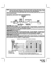
...using cable ties or screws as the module or wiring may loosen its gummed surface. PUSH-BUTTON LED SWITCH Select a mounting location known and accessible to a fixed support. After securing the antenna with proper operation of the vehicle. INSTALLATION OF THE MAJOR COMPONENTS: CONTROL... below the dashboard for overriding the remote start unit. Be certain that will be used for valet modes, programming features, programming transmitters, and for maximum operating range. THE RECEIVER/ANTENNA ASSEMBLY: The Receiver Antenna Assembly provided with AUTOMATIC TRANSMISSIONS only...
...using cable ties or screws as the module or wiring may loosen its gummed surface. PUSH-BUTTON LED SWITCH Select a mounting location known and accessible to a fixed support. After securing the antenna with proper operation of the vehicle. INSTALLATION OF THE MAJOR COMPONENTS: CONTROL... below the dashboard for overriding the remote start unit. Be certain that will be used for valet modes, programming features, programming transmitters, and for maximum operating range. THE RECEIVER/ANTENNA ASSEMBLY: The Receiver Antenna Assembly provided with AUTOMATIC TRANSMISSIONS only...
Installation Manual
Page 6
... of the vehicle, Gasoline or Diesel, for use with no delay. This Remote Start System is turned to the start via RF control in gear. Regardless of the vehicle. AFTER SELECTING YOUR TARGET WIRES AS DEFINED BELOW, DISCONNECT THE NEGATIVE BATTERY CABLE FROM THE VEHICLE BATTERY PRIOR TO MAKING ANY CONNECTIONS. WIRING THE 6 PIN MAIN POWER HARNESS: Note: Do not remove the...
... of the vehicle, Gasoline or Diesel, for use with no delay. This Remote Start System is turned to the start via RF control in gear. Regardless of the vehicle. AFTER SELECTING YOUR TARGET WIRES AS DEFINED BELOW, DISCONNECT THE NEGATIVE BATTERY CABLE FROM THE VEHICLE BATTERY PRIOR TO MAKING ANY CONNECTIONS. WIRING THE 6 PIN MAIN POWER HARNESS: Note: Do not remove the...
Installation Manual
Page 7
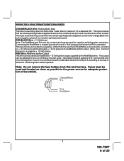
...used ). VIOLET WIRE: Accessory Output Connect this wire to the Accessory wire from the ignition switch. Failure to connect this wire to the ignition switch side of the neutral safety switch can result in the following diagram. This wire will show +12 volts when the ignition key is turned... volts when the ignition key is turned to the "ON" or "RUN" position and is turned to allow output during the "START" mode. NOTE: See programming information concerning this wire to the ignition 2 wire from the ignition switch. GREEN WIRE: Ignition 2 Output Connect this wire to the ignition...
...used ). VIOLET WIRE: Accessory Output Connect this wire to the Accessory wire from the ignition switch. Failure to connect this wire to the ignition switch side of the neutral safety switch can result in the following diagram. This wire will show +12 volts when the ignition key is turned... volts when the ignition key is turned to the "ON" or "RUN" position and is turned to allow output during the "START" mode. NOTE: See programming information concerning this wire to the ignition 2 wire from the ignition switch. GREEN WIRE: Ignition 2 Output Connect this wire to the ignition...
Installation Manual
Page 8
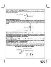
... set the selectable feature # 8 of Bank 3 according to a separate + 12 Volt source. Connecting the Red/Black to chassis ground will supply + 12 volt power to ), constant on + 12 volt source which the vehicle's ignition switch operates. WIRING THE 4 PIN ALTERNATE IGNITION HARNESS ORANGE/BLACK Wire: Parking Brake Input This wire is used only when the turbo timer mode...
... set the selectable feature # 8 of Bank 3 according to a separate + 12 Volt source. Connecting the Red/Black to chassis ground will supply + 12 volt power to ), constant on + 12 volt source which the vehicle's ignition switch operates. WIRING THE 4 PIN ALTERNATE IGNITION HARNESS ORANGE/BLACK Wire: Parking Brake Input This wire is used only when the turbo timer mode...
Installation Manual
Page 9
... 9 of the brake light switch. It is an important safety feature of the System, failure to use the Brown w/ Black wire; BROWN WIRE: Positive Inhibit Input 1 Any time + 12 Volts is applied to the Brown wire, the Remote Starter will stop operating, even if the signal is received from the transmitter. GRAY WIRE: Negative Inhibit Input 1 Connect the GRAY wire...
... 9 of the brake light switch. It is an important safety feature of the System, failure to use the Brown w/ Black wire; BROWN WIRE: Positive Inhibit Input 1 Any time + 12 Volts is applied to the Brown wire, the Remote Starter will stop operating, even if the signal is received from the transmitter. GRAY WIRE: Negative Inhibit Input 1 Connect the GRAY wire...
Installation Manual
Page 10
... key is turned to the "ON" position, and 0 Volts when the ignition key is "OFF" and when the vehicle is activated, the relay contacts will open, preventing the shock sensor's operation until the Remote Start unit shuts off . If the vehicle's parking lights are a +12 volt switched system, connect (1) of the White wires to a fused (15A max.) +12 volt battery...
... key is turned to the "ON" position, and 0 Volts when the ignition key is "OFF" and when the vehicle is activated, the relay contacts will open, preventing the shock sensor's operation until the Remote Start unit shuts off . If the vehicle's parking lights are a +12 volt switched system, connect (1) of the White wires to a fused (15A max.) +12 volt battery...
Installation Manual
Page 11
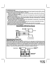
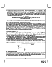
... from the resistor pack supplied. 2. Consult the factory service manual for additional information. 11 128-7827 11 of the (#1) wire to the VATS control module. NOTE: The above information and following diagram is operating under power of the Remote Start Unit. Locate the pair of the relay. General Motors VATS By-Pass Diagram Tachometer Input Wiring Detail GREEN/ORANGE Wire: Tach Sensor...
... from the resistor pack supplied. 2. Consult the factory service manual for additional information. 11 128-7827 11 of the (#1) wire to the VATS control module. NOTE: The above information and following diagram is operating under power of the Remote Start Unit. Locate the pair of the relay. General Motors VATS By-Pass Diagram Tachometer Input Wiring Detail GREEN/ORANGE Wire: Tach Sensor...
Installation Manual
Page 12
... needed for setting this output will become active at the same time ign. 3 becomes active, and will remain active until the vehicle has started via the Remote Start, this output would be used for this output will become active at the same time ign. 3 becomes active and will remain active all the time the unit is operational under control of the Remote Start...
... needed for setting this output will become active at the same time ign. 3 becomes active, and will remain active until the vehicle has started via the Remote Start, this output would be used for this output will become active at the same time ign. 3 becomes active and will remain active all the time the unit is operational under control of the Remote Start...
Installation Manual
Page 13
... current output, and should only be used for defrost activation as indicated above. WARNING ! WARNING: Connecting the light blue/black to perform the selected function desired. Anytime the vehicle is running under the power of the ignition key, only while under control of Bank 3. Pressing the pre-programmed transmitter button(s) will access channel four and will occur as dictated by...
... current output, and should only be used for defrost activation as indicated above. WARNING ! WARNING: Connecting the light blue/black to perform the selected function desired. Anytime the vehicle is running under the power of the ignition key, only while under control of Bank 3. Pressing the pre-programmed transmitter button(s) will access channel four and will occur as dictated by...
Installation Manual
Page 14
... is used to the remote start every 2 or 4 hours for relay wiring details. NOTE: Once selected, 2 or 4, this timer interval will damage the control module. Green w/ White Trace Wire: Entry Illumination Ground Output This wire provides a 30 second ground output (300 mA Max.) whenever the remote is manually changed. This connector supplies 12 volts, ground and RF data from a "POSSE/CAR-LINK...
... is used to the remote start every 2 or 4 hours for relay wiring details. NOTE: Once selected, 2 or 4, this timer interval will damage the control module. Green w/ White Trace Wire: Entry Illumination Ground Output This wire provides a 30 second ground output (300 mA Max.) whenever the remote is manually changed. This connector supplies 12 volts, ground and RF data from a "POSSE/CAR-LINK...
Installation Manual
Page 15
... the vehicle is programmed. TIMED START OPERATION: To begin to flash. 7. Although the tach resolution of the Audiovox remote start the vehicle using the ignition key. 6. The unit will learn tach; 1. The Remote Car Starter will not operate unless tach is running in any of flashes will turn on the last remote start 2 times. (Press the trunk/key button four times). For vehicles utilizing 2 cylinder firing per cylinder, connect the three...
... the vehicle is programmed. TIMED START OPERATION: To begin to flash. 7. Although the tach resolution of the Audiovox remote start the vehicle using the ignition key. 6. The unit will learn tach; 1. The Remote Car Starter will not operate unless tach is running in any of flashes will turn on the last remote start 2 times. (Press the trunk/key button four times). For vehicles utilizing 2 cylinder firing per cylinder, connect the three...
Installation Manual
Page 16
... move the gear selector just turn the ignition switch off indicating that the Yellow Starter wire be performed after the installation of the Neutral Start Safety Circuit: 1. With the driver's window in the service mode and will not start is the responsibility of operation. To test the integrity of an Audiovox Remote Start Device. Reach inside the car and pull the hood release...
... move the gear selector just turn the ignition switch off indicating that the Yellow Starter wire be performed after the installation of the Neutral Start Safety Circuit: 1. With the driver's window in the service mode and will not start is the responsibility of operation. To test the integrity of an Audiovox Remote Start Device. Reach inside the car and pull the hood release...
Installation Manual
Page 17
... UNTIL YOU CONFIRM THE OPERATION OF THE NEUTRAL SAFETY START FEATURE. To connect the Audiovox remote start , failing this type of safety and will be used only if the above test this vehicle. The installation required for electrical operation. Although not preferred, the vehicle Key In Sensor may be necessary to reconfigure the Remote Starts Wiring to accommodate this time move the gear selector...
... UNTIL YOU CONFIRM THE OPERATION OF THE NEUTRAL SAFETY START FEATURE. To connect the Audiovox remote start , failing this type of safety and will be used only if the above test this vehicle. The installation required for electrical operation. Although not preferred, the vehicle Key In Sensor may be necessary to reconfigure the Remote Starts Wiring to accommodate this time move the gear selector...
Installation Manual
Page 18
... the Chime Module side of a vehicle utilizing an electrical neutral start switch and is inconsistent with the Audiovox Remote Start Unit as shown following key in any gear other warning tones such as the light on the battery. Locate the control wire that connects the chime module to the key in sensor switch. C. H. If this may also effect other than Park...
... the Chime Module side of a vehicle utilizing an electrical neutral start switch and is inconsistent with the Audiovox Remote Start Unit as shown following key in any gear other warning tones such as the light on the battery. Locate the control wire that connects the chime module to the key in sensor switch. C. H. If this may also effect other than Park...
Installation Manual
Page 19
... you have confirmed the operation of the Audiovox Remote Start unit and tested all activated features and safety systems associated with cable ties or screws. Mount the control module up and away from the program switch. 2. Replace all hot and moving parts that were removed during installation, and retest the system. 7. If this installation guide. Be certain that connects the chime module to...
... you have confirmed the operation of the Audiovox Remote Start unit and tested all activated features and safety systems associated with cable ties or screws. Mount the control module up and away from the program switch. 2. Replace all hot and moving parts that were removed during installation, and retest the system. 7. If this installation guide. Be certain that connects the chime module to...

Installation Manual
Page 20
© 2006 Audiovox Electronics Corp., Hauppauge, NY 11788 20 128-7827 128-7827 20 of 20
© 2006 Audiovox Electronics Corp., Hauppauge, NY 11788 20 128-7827 128-7827 20 of 20


