Motherboard DIY Troubleshooting Guide
Page 6
... using, contact your dealer immediately. • To avoid short circuits, keep paper clips, screws, and staples away from the motherboard, ensure that the power cables for the devices are unplugged before the signal cables are connected. Safety information Electrical safety •... cables are not damaged. Operation safety • Before installing the motherboard and adding devices on a stable surface. • If you add a device. • Before connecting or removing signal cables from connectors, slots, sockets and circuitry. • Avoid dust, humidity, and temperature extremes....
... using, contact your dealer immediately. • To avoid short circuits, keep paper clips, screws, and staples away from the motherboard, ensure that the power cables for the devices are unplugged before the signal cables are connected. Safety information Electrical safety •... cables are not damaged. Operation safety • Before installing the motherboard and adding devices on a stable surface. • If you add a device. • Before connecting or removing signal cables from connectors, slots, sockets and circuitry. • Avoid dust, humidity, and temperature extremes....
Motherboard DIY Troubleshooting Guide
Page 12
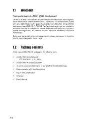
... future upgrades or system reconfiguration, this chapter provides technical information about the motherboard. Before you for socket A processors. Unique ASUS features such as ASUS C.O.P., ASUS Q-Fan Technology and more are included to deliver the maximum performance for buying the ASUS® A7N8X-X motherboard! The ASUS A7N8X-X motherboard is loaded with the most advanced technologies to ensure the best user...
... future upgrades or system reconfiguration, this chapter provides technical information about the motherboard. Before you for socket A processors. Unique ASUS features such as ASUS C.O.P., ASUS Q-Fan Technology and more are included to deliver the maximum performance for buying the ASUS® A7N8X-X motherboard! The ASUS A7N8X-X motherboard is loaded with the most advanced technologies to ensure the best user...
Motherboard DIY Troubleshooting Guide
Page 14
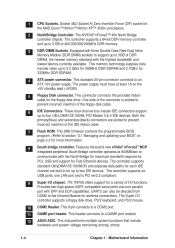
...disk cable. 6 IDE Connectors. This 9-pin connects to a GAME port module. 12 ASUS ASIC. This chip performs multiple system functions that include hardware and system voltage monitoring among others. 1-4 Chapter 1: Motherboard Information UART2 can also be directed from COM2 to 3GB of DDR DRAM, the newest... power supply. ITE IT8708 offers support for up to prevent incorrect insertion of 400/333/266/200MHz DDR memory. 3 DDR DIMM Sockets. This 2Mb firmware contains the programmable BIOS program. (Refer to two IDE devices. The controller supports six USB ports, one parallel...
...disk cable. 6 IDE Connectors. This 9-pin connects to a GAME port module. 12 ASUS ASIC. This chip performs multiple system functions that include hardware and system voltage monitoring among others. 1-4 Chapter 1: Motherboard Information UART2 can also be directed from COM2 to 3GB of DDR DRAM, the newest... power supply. ITE IT8708 offers support for up to prevent incorrect insertion of 400/333/266/200MHz DDR memory. 3 DDR DIMM Sockets. This 2Mb firmware contains the programmable BIOS program. (Refer to two IDE devices. The controller supports six USB ports, one parallel...
Motherboard DIY Troubleshooting Guide
Page 16
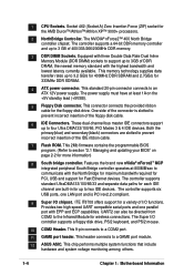
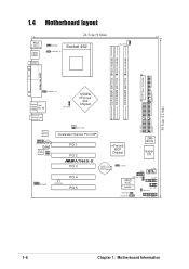
30.5cm (12.0in) 1.4 Motherboard layout PS/2 T: Mouse B: Keyboard USB3 USB4 COM1 24.5cm (9.64in) KBPWR1 USBPWR_34 Socket 462 CPU_FAN1 ATX Power Connector DDR DIMM1 (64/72 bit, 184-pin module) DDR DIMM2 (64/72 bit, 184-pin module) DDR DIMM3 (64/72 ...) PCI 1 PCI 2 ®A7N8X-X PCI 3 nForce2 MCP Chipset CR2032 3V Lithium Cell CMOS Power CLRTC1 2Mb BIOS Super I/O USB56 COM2 MODEM1 PWR_LED1 PCI 4 PCI 5 USBPWR_56 ASUS ASIC with Hardware Monitor GAME1 IR_CON1 IDELED1 PWRTMP1 CHASSIS1 CTRL_PANEL1 1-6 Chapter 1: Motherboard Information
30.5cm (12.0in) 1.4 Motherboard layout PS/2 T: Mouse B: Keyboard USB3 USB4 COM1 24.5cm (9.64in) KBPWR1 USBPWR_34 Socket 462 CPU_FAN1 ATX Power Connector DDR DIMM1 (64/72 bit, 184-pin module) DDR DIMM2 (64/72 bit, 184-pin module) DDR DIMM3 (64/72 ...) PCI 1 PCI 2 ®A7N8X-X PCI 3 nForce2 MCP Chipset CR2032 3V Lithium Cell CMOS Power CLRTC1 2Mb BIOS Super I/O USB56 COM2 MODEM1 PWR_LED1 PCI 4 PCI 5 USBPWR_56 ASUS ASIC with Hardware Monitor GAME1 IR_CON1 IDELED1 PWRTMP1 CHASSIS1 CTRL_PANEL1 1-6 Chapter 1: Motherboard Information
Motherboard DIY Troubleshooting Guide
Page 17
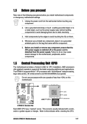
Hold components by the edges to the motherboard, peripherals, and/or components. 1.6 Central Processing Unit (CPU) The motherboard provides a Socket A (462) for CPU installation. Whenever you uninstall any motherboard settings. 1. ASUS A7N8X-X Motherboard 1-7 Failure to do so may cause severe damage to avoid touching the ICs on them due to support all the latest computing platforms and...
Hold components by the edges to the motherboard, peripherals, and/or components. 1.6 Central Processing Unit (CPU) The motherboard provides a Socket A (462) for CPU installation. Whenever you uninstall any motherboard settings. 1. ASUS A7N8X-X Motherboard 1-7 Failure to do so may cause severe damage to avoid touching the ICs on them due to support all the latest computing platforms and...
Motherboard DIY Troubleshooting Guide
Page 18
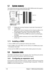
Visit ASUS website (www.asus.com) for latest DDR400 Qualified Vendor List. 1.7.1 Installing a DIMM 1. Align a DIMM on the DIMM exactly match the notches in the socket. 3. The following sub-sections describe the slots and the expansion cards that supports up to 3GB non-ECC PC3200/...the module are not supported. 2. Generally, an IRQ must be exclusively assigned to one direction. 1.7 System memory The motherboard has three Double Data Rate (DDR) DIMM sockets that they support. 1.8.1 Configuring an expansion card Some expansion cards need an IRQ to operate. Firmly insert the DIMM...
Visit ASUS website (www.asus.com) for latest DDR400 Qualified Vendor List. 1.7.1 Installing a DIMM 1. Align a DIMM on the DIMM exactly match the notches in the socket. 3. The following sub-sections describe the slots and the expansion cards that supports up to 3GB non-ECC PC3200/...the module are not supported. 2. Generally, an IRQ must be exclusively assigned to one direction. 1.7 System memory The motherboard has three Double Data Rate (DDR) DIMM sockets that they support. 1.8.1 Configuring an expansion card Some expansion cards need an IRQ to operate. Firmly insert the DIMM...
A7N8X-X User's Manual
Page 6
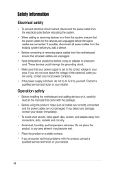
... in any damage, contact your dealer immediately. • To avoid short circuits, keep paper clips, screws, and staples away from the motherboard, ensure that your power supply is broken, do not try to fix it , carefully read all power cables are unplugged. • ... outlet you add a device. • Before connecting or removing signal cables from connectors, slots, sockets and circuitry. • Avoid dust, humidity, and temperature extremes. Operation safety • Before installing the motherboard and adding devices on a stable surface. • If you detect any area where it may...
... in any damage, contact your dealer immediately. • To avoid short circuits, keep paper clips, screws, and staples away from the motherboard, ensure that your power supply is broken, do not try to fix it , carefully read all power cables are unplugged. • ... outlet you add a device. • Before connecting or removing signal cables from connectors, slots, sockets and circuitry. • Avoid dust, humidity, and temperature extremes. Operation safety • Before installing the motherboard and adding devices on a stable surface. • If you detect any area where it may...

A7N8X-X User's Manual
Page 12
... value-added features for socket A processors. Before you for the following items. 1-2 For future upgrades or system reconfiguration, this chapter provides technical information about the motherboard. 1.1 Welcome! The ASUS A7N8X-X motherboard is loaded with the list below. 1.2 Package contents ASUS A7N8X-X motherboard ATX form factor: 12 in x 9.6 in a motherboard. Unique ASUS features such as ASUS C.O.P., ASUS Q-Fan Technology and more...
... value-added features for socket A processors. Before you for the following items. 1-2 For future upgrades or system reconfiguration, this chapter provides technical information about the motherboard. 1.1 Welcome! The ASUS A7N8X-X motherboard is loaded with the list below. 1.2 Package contents ASUS A7N8X-X motherboard ATX form factor: 12 in x 9.6 in a motherboard. Unique ASUS features such as ASUS C.O.P., ASUS Q-Fan Technology and more...
A7N8X-X User's Manual
Page 14
...Managing and updating your BIOS" on the +5V standby lead (+5VSB). This 9-pin connects to a GAME port module. ASUS ASIC. DDR DIMM Sockets. This 2Mb firmware contains the programmable BIOS program. (Refer to prevent incorrect insertion of I/O functions. Equipped with three Double... system functions that include hardware and system voltage monitoring among others. 3 4 5 6 7 8 9 10 11 12 1-4 Chapter 1: Motherboard Information This standard 20-pin connector connects to two IDE devices. Features the brand new nVidia® nForce2™ MCP integrated peripheral South Bridge...
...Managing and updating your BIOS" on the +5V standby lead (+5VSB). This 9-pin connects to a GAME port module. ASUS ASIC. DDR DIMM Sockets. This 2Mb firmware contains the programmable BIOS program. (Refer to prevent incorrect insertion of I/O functions. Equipped with three Double... system functions that include hardware and system voltage monitoring among others. 3 4 5 6 7 8 9 10 11 12 1-4 Chapter 1: Motherboard Information This standard 20-pin connector connects to two IDE devices. Features the brand new nVidia® nForce2™ MCP integrated peripheral South Bridge...

A7N8X-X User's Manual
Page 16
1.4 T: Mouse B: Keyboard Motherboard layout 24.5cm (9.64in) KBPWR1 PS/2 Socket 462 DDR DIMM1 (64/72 bit, 184-pin module) DDR DIMM2 (64/72 bit, 184-pin module) CPU_FAN1 USB3 USB4 COM1 USBPWR_34 DDR DIMM3 (64/... 2 ® Super I/O A7N8X-X CR2032 3V Lithium Cell CMOS Power CLRTC1 COM2 USB56 PCI 3 PCI 4 MODEM1 PWR_LED1 USBPWR_56 GAME1 PCI 5 with Hardware Monitor IDELED1 PWRTMP1 CHASSIS1 ASUS ASIC IR_CON1 CTRL_PANEL1 1-6 Chapter 1: Motherboard Information PRI_IDE1 30.5cm (12.0in) USB1 RJ-45 USB2 Top: nForce2 400 Chipset CPU_FSB FLOPPY1 nVidia ATX Power Connector
1.4 T: Mouse B: Keyboard Motherboard layout 24.5cm (9.64in) KBPWR1 PS/2 Socket 462 DDR DIMM1 (64/72 bit, 184-pin module) DDR DIMM2 (64/72 bit, 184-pin module) CPU_FAN1 USB3 USB4 COM1 USBPWR_34 DDR DIMM3 (64/... 2 ® Super I/O A7N8X-X CR2032 3V Lithium Cell CMOS Power CLRTC1 COM2 USB56 PCI 3 PCI 4 MODEM1 PWR_LED1 USBPWR_56 GAME1 PCI 5 with Hardware Monitor IDELED1 PWRTMP1 CHASSIS1 ASUS ASIC IR_CON1 CTRL_PANEL1 1-6 Chapter 1: Motherboard Information PRI_IDE1 30.5cm (12.0in) USB1 RJ-45 USB2 Top: nForce2 400 Chipset CPU_FSB FLOPPY1 nVidia ATX Power Connector

A7N8X-X User's Manual
Page 17
... component. 2. Failure to do so may cause severe damage to support all the latest computing platforms and applications. ASUS A7N8X-X Motherboard 1-7 Take note of less than 1GHz on this indicator while orienting the CPU. The A7N8X-X supports Athlon™...strap or touch a safely grounded object or to a metal object, such as the power supply case, before touching any motherboard settings. 1.6 Central Processing Unit (CPU) The motherboard provides a Socket A (462) for CPU installation. Before you proceed 1. CPU NOTCH TO INNER CORNER LOCK LEVER ® A7N8X-X AMD...
... component. 2. Failure to do so may cause severe damage to support all the latest computing platforms and applications. ASUS A7N8X-X Motherboard 1-7 Take note of less than 1GHz on this indicator while orienting the CPU. The A7N8X-X supports Athlon™...strap or touch a safely grounded object or to a metal object, such as the power supply case, before touching any motherboard settings. 1.6 Central Processing Unit (CPU) The motherboard provides a Socket A (462) for CPU installation. Before you proceed 1. CPU NOTCH TO INNER CORNER LOCK LEVER ® A7N8X-X AMD...

A7N8X-X User's Manual
Page 18
...into place. 1.8 Expansion slots The A7N8X-X motherboard has six (6) expansion slots. Make sure the notches on the socket. 1.7 System memory The motherboard has three Double Data Rate (DDR) DIMM sockets that supports up to one direction. Visit ASUS website (www.asus.com) for latest DDR400 Qualified Vendor List. ...174; A7N8X-X 80 Pins A7N8X-X 184-Pin DDR DIMM Sockets 1. DIMMs with a notch so that it fits in the socket. 3. Make sure the memory frequency and bus frequency setting in use. 1-8 Chapter 1: Motherboard Information A DDR DIMM is keyed with more than 8 ...
...into place. 1.8 Expansion slots The A7N8X-X motherboard has six (6) expansion slots. Make sure the notches on the socket. 1.7 System memory The motherboard has three Double Data Rate (DDR) DIMM sockets that supports up to one direction. Visit ASUS website (www.asus.com) for latest DDR400 Qualified Vendor List. ...174; A7N8X-X 80 Pins A7N8X-X 184-Pin DDR DIMM Sockets 1. DIMMs with a notch so that it fits in the socket. 3. Make sure the memory frequency and bus frequency setting in use. 1-8 Chapter 1: Motherboard Information A DDR DIMM is keyed with more than 8 ...


