Motherboard DIY Troubleshooting Guide
Page 14
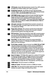
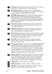
Socket 462 (Socket A) Zero Insertion Force (ZIF) socket for more information) 8 South bridge controller. The power supply must have at 800MB/sec to 3GB of 400/333/266/200MHz DDR memory. 3 DDR DIMM Sockets... multiple system functions that include hardware and system voltage monitoring among others. 1-4 Chapter 1: Motherboard Information Features the brand new nVidia® nForce2™ MCP integrated peripheral South Bridge controller...for PCI, USB and support for up to a GAME port module. 12 ASUS ASIC. The controller supports standard UltraDMA133/100/66/33 and separate data paths ...
Socket 462 (Socket A) Zero Insertion Force (ZIF) socket for more information) 8 South bridge controller. The power supply must have at 800MB/sec to 3GB of 400/333/266/200MHz DDR memory. 3 DDR DIMM Sockets... multiple system functions that include hardware and system voltage monitoring among others. 1-4 Chapter 1: Motherboard Information Features the brand new nVidia® nForce2™ MCP integrated peripheral South Bridge controller...for PCI, USB and support for up to a GAME port module. 12 ASUS ASIC. The controller supports standard UltraDMA133/100/66/33 and separate data paths ...
Motherboard DIY Troubleshooting Guide
Page 16
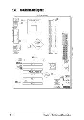
30.5cm (12.0in) 1.4 Motherboard layout PS/2 T: Mouse B: Keyboard USB3 USB4 COM1 24.5cm (9.64in) KBPWR1 USBPWR_34 Socket 462 CPU_FAN1 ATX Power Connector DDR DIMM1 (64/72 bit, 184-pin module) DDR DIMM2 (64/72 bit, 184-pin module) DDR DIMM3 (64/72 bit, ...) PCI 1 PCI 2 ®A7N8X-X PCI 3 nForce2 MCP Chipset CR2032 3V Lithium Cell CMOS Power CLRTC1 2Mb BIOS Super I/O USB56 COM2 MODEM1 PWR_LED1 PCI 4 PCI 5 USBPWR_56 ASUS ASIC with Hardware Monitor GAME1 IR_CON1 IDELED1 PWRTMP1 CHASSIS1 CTRL_PANEL1 1-6 Chapter 1: Motherboard Information
30.5cm (12.0in) 1.4 Motherboard layout PS/2 T: Mouse B: Keyboard USB3 USB4 COM1 24.5cm (9.64in) KBPWR1 USBPWR_34 Socket 462 CPU_FAN1 ATX Power Connector DDR DIMM1 (64/72 bit, 184-pin module) DDR DIMM2 (64/72 bit, 184-pin module) DDR DIMM3 (64/72 bit, ...) PCI 1 PCI 2 ®A7N8X-X PCI 3 nForce2 MCP Chipset CR2032 3V Lithium Cell CMOS Power CLRTC1 2Mb BIOS Super I/O USB56 COM2 MODEM1 PWR_LED1 PCI 4 PCI 5 USBPWR_56 ASUS ASIC with Hardware Monitor GAME1 IR_CON1 IDELED1 PWRTMP1 CHASSIS1 CTRL_PANEL1 1-6 Chapter 1: Motherboard Information
Motherboard DIY Troubleshooting Guide
Page 17
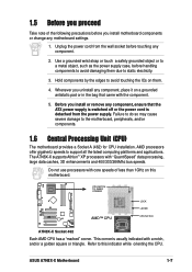
...supports Athlon™ XP processors with the component. 5. Hold components by the edges to the motherboard, peripherals, and/or components. 1.6 Central Processing Unit (CPU) The motherboard provides a Socket A (462) for CPU installation. Failure to do so may cause severe damage to avoid touching the ICs...usually indicated with core speeds of the following precautions before handling components to avoid damaging them . 4. ASUS A7N8X-X Motherboard 1-7 Before you install or remove any motherboard settings. 1. 1.5 Before you proceed Take note of less than 1GHz on them due to support...
...supports Athlon™ XP processors with the component. 5. Hold components by the edges to the motherboard, peripherals, and/or components. 1.6 Central Processing Unit (CPU) The motherboard provides a Socket A (462) for CPU installation. Failure to do so may cause severe damage to avoid touching the ICs...usually indicated with core speeds of the following precautions before handling components to avoid damaging them . 4. ASUS A7N8X-X Motherboard 1-7 Before you install or remove any motherboard settings. 1. 1.5 Before you proceed Take note of less than 1GHz on them due to support...
A7N8X-X User's Manual
Page 14
... and is slotted to 3GB of the floppy disk cable. This 9-pin connects to an ATX 12V power supply. ASUS ASIC. Socket 462 (Socket A) Zero Insertion Force (ZIF) socket for the floppy disk drive. This standard 20-pin connector connects to a COM2 port. Floppy Disk connector. Flash ROM...system voltage monitoring among others. 3 4 5 6 7 8 9 10 11 12 1-4 Chapter 1: Motherboard Information The power supply must have at 800MB/sec to two IDE devices. COM2 Header. DDR DIMM Sockets. One side of 400/333/266/200MHz DDR memory. Features the brand new nVidia® nForce2™...
... and is slotted to 3GB of the floppy disk cable. This 9-pin connects to an ATX 12V power supply. ASUS ASIC. Socket 462 (Socket A) Zero Insertion Force (ZIF) socket for the floppy disk drive. This standard 20-pin connector connects to a COM2 port. Floppy Disk connector. Flash ROM...system voltage monitoring among others. 3 4 5 6 7 8 9 10 11 12 1-4 Chapter 1: Motherboard Information The power supply must have at 800MB/sec to two IDE devices. COM2 Header. DDR DIMM Sockets. One side of 400/333/266/200MHz DDR memory. Features the brand new nVidia® nForce2™...

A7N8X-X User's Manual
Page 16
1.4 T: Mouse B: Keyboard Motherboard layout 24.5cm (9.64in) KBPWR1 PS/2 Socket 462 DDR DIMM1 (64/72 bit, 184-pin module) DDR DIMM2 (64/72 bit, 184-pin module) CPU_FAN1 USB3 USB4 COM1 USBPWR_34 DDR DIMM3 (64/72 ... 2 ® Super I/O A7N8X-X CR2032 3V Lithium Cell CMOS Power CLRTC1 COM2 USB56 PCI 3 PCI 4 MODEM1 PWR_LED1 USBPWR_56 GAME1 PCI 5 with Hardware Monitor IDELED1 PWRTMP1 CHASSIS1 ASUS ASIC IR_CON1 CTRL_PANEL1 1-6 Chapter 1: Motherboard Information PRI_IDE1 30.5cm (12.0in) USB1 RJ-45 USB2 Top: nForce2 400 Chipset CPU_FSB FLOPPY1 nVidia ATX Power Connector
1.4 T: Mouse B: Keyboard Motherboard layout 24.5cm (9.64in) KBPWR1 PS/2 Socket 462 DDR DIMM1 (64/72 bit, 184-pin module) DDR DIMM2 (64/72 bit, 184-pin module) CPU_FAN1 USB3 USB4 COM1 USBPWR_34 DDR DIMM3 (64/72 ... 2 ® Super I/O A7N8X-X CR2032 3V Lithium Cell CMOS Power CLRTC1 COM2 USB56 PCI 3 PCI 4 MODEM1 PWR_LED1 USBPWR_56 GAME1 PCI 5 with Hardware Monitor IDELED1 PWRTMP1 CHASSIS1 ASUS ASIC IR_CON1 CTRL_PANEL1 1-6 Chapter 1: Motherboard Information PRI_IDE1 30.5cm (12.0in) USB1 RJ-45 USB2 Top: nForce2 400 Chipset CPU_FSB FLOPPY1 nVidia ATX Power Connector

A7N8X-X User's Manual
Page 17
Before you uninstall any component, ensure that came with core speeds of the following precautions before touching any motherboard settings. 1.6 Central Processing Unit (CPU) The motherboard provides a Socket A (462) for CPU installation. ASUS A7N8X-X Motherboard 1-7 1.5 Before you install motherboard components or change any component. 2. Hold components by the edges to avoid touching the ICs on this indicator while...
Before you uninstall any component, ensure that came with core speeds of the following precautions before touching any motherboard settings. 1.6 Central Processing Unit (CPU) The motherboard provides a Socket A (462) for CPU installation. ASUS A7N8X-X Motherboard 1-7 1.5 Before you install motherboard components or change any component. 2. Hold components by the edges to avoid touching the ICs on this indicator while...


