
Motherboard DIY Troubleshooting Guide
Page 6
... using the product, make sure all cables are correctly connected and the power cables are connected. Operation safety • Before installing the motherboard and adding devices on a stable surface. • If you are unplugged. • Seek professional assistance before using an adpater or ... damage, contact your dealer immediately. • To avoid short circuits, keep paper clips, screws, and staples away from connectors, slots, sockets and circuitry. • Avoid dust, humidity, and temperature extremes. vi Do not place the product in your retailer. Contact a qualified...
... using the product, make sure all cables are correctly connected and the power cables are connected. Operation safety • Before installing the motherboard and adding devices on a stable surface. • If you are unplugged. • Seek professional assistance before using an adpater or ... damage, contact your dealer immediately. • To avoid short circuits, keep paper clips, screws, and staples away from connectors, slots, sockets and circuitry. • Avoid dust, humidity, and temperature extremes. vi Do not place the product in your retailer. Contact a qualified...

Motherboard DIY Troubleshooting Guide
Page 12
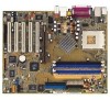
... more are included to deliver the maximum performance for guaranteed consumer satisfaction. For future upgrades or system reconfiguration, this chapter provides technical information about the motherboard. The ASUS A7N8X motherboard is loaded with value-added features for socket A processors. Before you for a 3.5-inch floppy drive Bag of extra jumper caps COM2 bracket I/O shield User's Manual...
... more are included to deliver the maximum performance for guaranteed consumer satisfaction. For future upgrades or system reconfiguration, this chapter provides technical information about the motherboard. The ASUS A7N8X motherboard is loaded with value-added features for socket A processors. Before you for a 3.5-inch floppy drive Bag of extra jumper caps COM2 bracket I/O shield User's Manual...

Motherboard DIY Troubleshooting Guide
Page 14
...maximum bandwith required for PCI, USB and support for 333MHz DDR SDRAM. 4 ATX power connector. Socket 462 (Socket A) Zero Insertion Force (ZIF) socket for more information) 8 South bridge controller. This 2Mb firmware contains the programmable BIOS program. ...(Refer to the Infrared Module for the floppy disk drive. The controller supports standard UltraDMA133/100/66/33 and separate data paths for each IDE channel are slotted to a GAME port module. 1-4 Chapter 1: Motherboard...
...maximum bandwith required for PCI, USB and support for 333MHz DDR SDRAM. 4 ATX power connector. Socket 462 (Socket A) Zero Insertion Force (ZIF) socket for more information) 8 South bridge controller. This 2Mb firmware contains the programmable BIOS program. ...(Refer to the Infrared Module for the floppy disk drive. The controller supports standard UltraDMA133/100/66/33 and separate data paths for each IDE channel are slotted to a GAME port module. 1-4 Chapter 1: Motherboard...

Motherboard DIY Troubleshooting Guide
Page 16
30.5cm (12.0in) 1.4 Motherboard layout PS/2 T: Mouse B: Keyboard USB3 USB4 COM1 24.5cm (9.64in) KBPWR1 USBPWR_34 Socket 462 CPU_FAN1 ATX Power Connector DDR DIMM1 (64/72 bit, 184-pin module) DDR DIMM2 (64/72 bit, 184-pin module) DDR DIMM3 (64/72...SPP (Ultra400) Chipset 0 1 23 4 5 PRI_IDE1 SEC_IDE1 PWR_FAN1 CHA_FAN1 Realtek RTL8201 CD1 FPAUDIO1 AUX1 Audio Codec SPDIF1 Accelerated Graphics Port (AGP Pro) AGP_WARN1 PCI 1 PCI 2 ® A7N8X PCI 3 nForce2 MCP Chipset CR2032 3V Lithium Cell CMOS Power CLRTC1 2Mb BIOS Super I/O USB56 COM2 MODEM1 PWR_LED1 PCI 4 PCI 5 USBPWR_56...
30.5cm (12.0in) 1.4 Motherboard layout PS/2 T: Mouse B: Keyboard USB3 USB4 COM1 24.5cm (9.64in) KBPWR1 USBPWR_34 Socket 462 CPU_FAN1 ATX Power Connector DDR DIMM1 (64/72 bit, 184-pin module) DDR DIMM2 (64/72 bit, 184-pin module) DDR DIMM3 (64/72...SPP (Ultra400) Chipset 0 1 23 4 5 PRI_IDE1 SEC_IDE1 PWR_FAN1 CHA_FAN1 Realtek RTL8201 CD1 FPAUDIO1 AUX1 Audio Codec SPDIF1 Accelerated Graphics Port (AGP Pro) AGP_WARN1 PCI 1 PCI 2 ® A7N8X PCI 3 nForce2 MCP Chipset CR2032 3V Lithium Cell CMOS Power CLRTC1 2Mb BIOS Super I/O USB56 COM2 MODEM1 PWR_LED1 PCI 4 PCI 5 USBPWR_56...

Motherboard DIY Troubleshooting Guide
Page 17
...power supply case, before you install or remove any motherboard settings. 1. Hold components by the edges to this motherboard. ® A7N8X CPU NOTCH TO INNER CORNER AMD™ CPU LOCK LEVER CPU NOTCH A7N8X Socket 462 Each AMD CPU has a "marked" corner.... The motherboard provides a Socket A (462) for CPU installation. Unplug the power cord from the power supply. The A7N8X supports Athlon™ XP processors with core speeds of the following precautions before handling components to avoid damaging them . 4. ASUS A7N8X Motherboard 1-7 Before you install motherboard components...
...power supply case, before you install or remove any motherboard settings. 1. Hold components by the edges to this motherboard. ® A7N8X CPU NOTCH TO INNER CORNER AMD™ CPU LOCK LEVER CPU NOTCH A7N8X Socket 462 Each AMD CPU has a "marked" corner.... The motherboard provides a Socket A (462) for CPU installation. Unplug the power cord from the power supply. The A7N8X supports Athlon™ XP processors with core speeds of the following precautions before handling components to avoid damaging them . 4. ASUS A7N8X Motherboard 1-7 Before you install motherboard components...
Motherboard DIY Troubleshooting Guide
Page 18
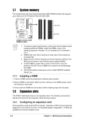
... Pins A7N8X 184-Pin DDR DIMM Sockets 1. Firmly insert the DIMM into the socket until the retaining clips lock into a socket to avoid damaging the DIMM. 5. 1.7 System memory The motherboard has three Double Data Rate (DDR) DIMM sockets that they support. 1.8.1 Configuring an expansion card Some expansion cards need an IRQ to operate. Visit ASUS website (www.asus...
... Pins A7N8X 184-Pin DDR DIMM Sockets 1. Firmly insert the DIMM into the socket until the retaining clips lock into a socket to avoid damaging the DIMM. 5. 1.7 System memory The motherboard has three Double Data Rate (DDR) DIMM sockets that they support. 1.8.1 Configuring an expansion card Some expansion cards need an IRQ to operate. Visit ASUS website (www.asus...

A7N8X User Manual
Page 5
ASUS A7N8X-Motherboard 5 Optionale Komponenten werden in dem obigen Motherboard-Layout grau dargestellt. Deutsch 1. Motherboard-Layout PS/2 T: Mouse B: Keyboard USB3 USB4 COM1 KBPWR1 USBPWR_34 Socket 462 CPU_FAN1 KBPWR1 12 23 +5V (Default) +5VSB DDR DIMM1 (64/72 bit, 184-pin module) DDR ... PWR_FAN1 CHA_FAN1 Realtek RTL8201 CD1 FPAUDIO1 AUX1 Audio Codec SPDIF1 Accelerated Graphics Port (AGP Pro) AGP_WARN1 PCI 1 PCI 2 ® A7N8X PCI 3 nForce2 MCP Chipset CR2032 3V Lithium Cell CMOS Power CLRTC1 2Mb BIOS Super I/O USB56 COM2 MODEM1 PWR_LED1 PCI 4 PCI 5 USBPWR_56...
ASUS A7N8X-Motherboard 5 Optionale Komponenten werden in dem obigen Motherboard-Layout grau dargestellt. Deutsch 1. Motherboard-Layout PS/2 T: Mouse B: Keyboard USB3 USB4 COM1 KBPWR1 USBPWR_34 Socket 462 CPU_FAN1 KBPWR1 12 23 +5V (Default) +5VSB DDR DIMM1 (64/72 bit, 184-pin module) DDR ... PWR_FAN1 CHA_FAN1 Realtek RTL8201 CD1 FPAUDIO1 AUX1 Audio Codec SPDIF1 Accelerated Graphics Port (AGP Pro) AGP_WARN1 PCI 1 PCI 2 ® A7N8X PCI 3 nForce2 MCP Chipset CR2032 3V Lithium Cell CMOS Power CLRTC1 2Mb BIOS Super I/O USB56 COM2 MODEM1 PWR_LED1 PCI 4 PCI 5 USBPWR_56...


