
Z9NH-D12 Series User Manual
Page 17
... SDVD 1 1 Application CD ASWM Enterprise SDVD 1 1 ASMB6-iKVM SDVD 1 1 Motherboard User Guide 1 1 Documentation ASMB6-iKVM User Guide 1 1 Cable Thermistor 2 2 Packing Qty. 10 pc per carton Z9NH-D12 1 1 1 1 1 1 2 ASUS Z9NH-D12 Series 1-3 1.1 Welcome! Thank you start installing the motherboard, and hardware devices on it another standout in your package with the list below. 1.2 Package contents Check...
... SDVD 1 1 Application CD ASWM Enterprise SDVD 1 1 ASMB6-iKVM SDVD 1 1 Motherboard User Guide 1 1 Documentation ASMB6-iKVM User Guide 1 1 Cable Thermistor 2 2 Packing Qty. 10 pc per carton Z9NH-D12 1 1 1 1 1 1 2 ASUS Z9NH-D12 Series 1-3 1.1 Welcome! Thank you start installing the motherboard, and hardware devices on it another standout in your package with the list below. 1.2 Package contents Check...
Z9NH-D12 Series User Manual
Page 19
... Intel Xeon® processor E5-2400 product family in LGA 1356 package with the Intel® EM64T (Extended Memory 64 Technology). ASUS Z9NH-D12 Series 1-5 Optimized Intel® Turbo Boost Technology Optimized Intel® Turbo Boost Technology further optimizes the processor's performance and automatically allows...it to your computer to support 3 channel (6 DIMM per CPU) DDR3 memory. With the correct serial number of the product, ASUS Technical Support team members can then offer a quicker and satisfying solution to run on 64-bit operating systems and access larger amounts of...
... Intel Xeon® processor E5-2400 product family in LGA 1356 package with the Intel® EM64T (Extended Memory 64 Technology). ASUS Z9NH-D12 Series 1-5 Optimized Intel® Turbo Boost Technology Optimized Intel® Turbo Boost Technology further optimizes the processor's performance and automatically allows...it to your computer to support 3 channel (6 DIMM per CPU) DDR3 memory. With the correct serial number of the product, ASUS Technical Support team members can then offer a quicker and satisfying solution to run on 64-bit operating systems and access larger amounts of...

Z9NH-D12 Series User Manual
Page 21
ASUS Z9NH-D12 Series 1-7 USB 2.0 technology The motherboard implements the Universal Serial Bus (USB) 2.0 specification, dramatically increasing the connection speed from the 12 Mbps bandwidth on USB 1.1 to a fast 480 Mbps on -demand upgrade kit for users. ASUS provides multiple SAS solutions for different...and purposes and PIKE saves lots of validation efforts and hardware cost for critical components. 1.4.2 Innovative ASUS features ASUS Fan Speed control technology The ASUS Fan Speed control technology smartly adjusts the fan speeds according to the system loading to ensure stable...
ASUS Z9NH-D12 Series 1-7 USB 2.0 technology The motherboard implements the Universal Serial Bus (USB) 2.0 specification, dramatically increasing the connection speed from the 12 Mbps bandwidth on USB 1.1 to a fast 480 Mbps on -demand upgrade kit for users. ASUS provides multiple SAS solutions for different...and purposes and PIKE saves lots of validation efforts and hardware cost for critical components. 1.4.2 Innovative ASUS features ASUS Fan Speed control technology The ASUS Fan Speed control technology smartly adjusts the fan speeds according to the system loading to ensure stable...

Z9NH-D12 Series User Manual
Page 24
Chapter summary 2 2.1 Before you proceed 2-3 2.2 Motherboard overview 2-4 2.3 Central Processing Unit (CPU 2-9 2.4 System memory 2-14 2.5 Expansion slots 2-17 2.6 Onboard LEDs 2-20 2.7 Jumpers 2-22 2.8 Connectors 2-27 ASUS Z9NH-D12 Series
Chapter summary 2 2.1 Before you proceed 2-3 2.2 Motherboard overview 2-4 2.3 Central Processing Unit (CPU 2-9 2.4 System memory 2-14 2.5 Expansion slots 2-17 2.6 Onboard LEDs 2-20 2.7 Jumpers 2-22 2.8 Connectors 2-27 ASUS Z9NH-D12 Series
Z9NH-D12 Series User Manual
Page 25
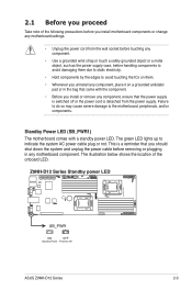
The green LED lights up to the motherboard, peripherals, and/or components. ASUS Z9NH-D12 Series 2-3 This is detached from the power supply. Failure to do so may cause severe damage to indicate the system AC power cable plug or ...
The green LED lights up to the motherboard, peripherals, and/or components. ASUS Z9NH-D12 Series 2-3 This is detached from the power supply. Failure to do so may cause severe damage to indicate the system AC power cable plug or ...

Z9NH-D12 Series User Manual
Page 27
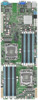
2.2.3 Motherboard layout Z9NH-D12/FDR Z9NH-D12/10G ASUS Z9NH-D12 Series 2-5
2.2.3 Motherboard layout Z9NH-D12/FDR Z9NH-D12/10G ASUS Z9NH-D12 Series 2-5
Z9NH-D12 Series User Manual
Page 29
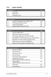
...) port 6. InfiniBand LED (Link/ ACT) (Z9NH-D12/FDR and Z9NH-D12/10G only) 7. CPU Warning LED (ERR_CPU1/2) 3. 2.2.4 Layout contents Slots/Sockets 1. CPU sockets 2. Baseboard Management Controller (BMC_LED1) 2. DM_LAN1 (RJ-45) port 2. USB 2.0 ports 1 and 2 4. InfiniBand (QSFP) (Z9NH-D12/FDR and Z9NH-D12/10G only) 8. Serial (COM1) port Page 2-27 2-27 2-27 2-27 2-27 2-27 2-27 2-27 2-27 ASUS Z9NH-D12 Series 2-7
...) port 6. InfiniBand LED (Link/ ACT) (Z9NH-D12/FDR and Z9NH-D12/10G only) 7. CPU Warning LED (ERR_CPU1/2) 3. 2.2.4 Layout contents Slots/Sockets 1. CPU sockets 2. Baseboard Management Controller (BMC_LED1) 2. DM_LAN1 (RJ-45) port 2. USB 2.0 ports 1 and 2 4. InfiniBand (QSFP) (Z9NH-D12/FDR and Z9NH-D12/10G only) 8. Serial (COM1) port Page 2-27 2-27 2-27 2-27 2-27 2-27 2-27 2-27 2-27 ASUS Z9NH-D12 Series 2-7
Z9NH-D12 Series User Manual
Page 31
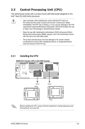
ASUS will process Return Merchandise Authorization (RMA) requests only if the motherboard comes with a surface mount LGA1356 socket designed for the Intel® Xeon E5-2400 .... • The product warranty does not cover damage to the PnP cap/socket contacts/motherboard components. ASUS will shoulder the cost of repair only if the damage is missing, or if you and the load lever is on the socket and the socket contacts are not bent. ASUS Z9NH-D12 Series 2-9 Contact your left.
ASUS will process Return Merchandise Authorization (RMA) requests only if the motherboard comes with a surface mount LGA1356 socket designed for the Intel® Xeon E5-2400 .... • The product warranty does not cover damage to the PnP cap/socket contacts/motherboard components. ASUS will shoulder the cost of repair only if the damage is missing, or if you and the load lever is on the socket and the socket contacts are not bent. ASUS Z9NH-D12 Series 2-9 Contact your left.

Z9NH-D12 Series User Manual
Page 33
... CPU that the heatsink will be in contact with preapplied thermal paste. Position the CPU over the socket, ensuring that it is toxic and inedible. ASUS Z9NH-D12 Series 2-11 The Thermal Interface Material is spread in only one correct orientation. Gold triangle mark CPU notch Alignment key The CPU fits in an...
... CPU that the heatsink will be in contact with preapplied thermal paste. Position the CPU over the socket, ensuring that it is toxic and inedible. ASUS Z9NH-D12 Series 2-11 The Thermal Interface Material is spread in only one correct orientation. Gold triangle mark CPU notch Alignment key The CPU fits in an...

Z9NH-D12 Series User Manual
Page 35
2.3.3 Installing the CPU heatsink To install the CPU heatsink: 1. Twist each of the installed CPU, ensuring that the four fasteners match the holes on top of the four screws with a Philips (cross) screwdriver just enough to attach the heatsink to completely secure the heatsink. A B B A ASUS Z9NH-D12 Series Tighten the four heatsink screws in a diagonal sequence. 2-13 When the four screws are attached, tighten them one by one to the motherboard. Place the heatsink on the motherboard. 2.
2.3.3 Installing the CPU heatsink To install the CPU heatsink: 1. Twist each of the installed CPU, ensuring that the four fasteners match the holes on top of the four screws with a Philips (cross) screwdriver just enough to attach the heatsink to completely secure the heatsink. A B B A ASUS Z9NH-D12 Series Tighten the four heatsink screws in a diagonal sequence. 2-13 When the four screws are attached, tighten them one by one to the motherboard. Place the heatsink on the motherboard. 2.

Z9NH-D12 Series User Manual
Page 37
... + CPU2 Configuration A2 A1 B2 B1 C2 C1 D2 D1 E2 E1 F2 F1 G2 G1 H2 H1 1 DIMM P 2 DIMMs P P 3 DIMMs P P P 4 DIMMs P P P P 6 DIMMs P P P P P P 12 DIMMs P P P P P P P P P P P P ASUS Z9NH-D12 Series 2-15 2.4.2 Memory Configurations You may install 2GB, 4GB, 8GB, and 16GB RDIMMs or 2GB, 4GB, and 8GB* with the same CAS latency. For optimum... ECC/Non-ECC UDIMMs or 8GB, 16GB and 32GB* LR-DIMMs into the DIMM sockets using the memory configurations in this section. • *Refer to ASUS Server AVL for latest update. • Start installing the DIMMs from the same vendor.
... + CPU2 Configuration A2 A1 B2 B1 C2 C1 D2 D1 E2 E1 F2 F1 G2 G1 H2 H1 1 DIMM P 2 DIMMs P P 3 DIMMs P P P 4 DIMMs P P P P 6 DIMMs P P P P P P 12 DIMMs P P P P P P P P P P P P ASUS Z9NH-D12 Series 2-15 2.4.2 Memory Configurations You may install 2GB, 4GB, 8GB, and 16GB RDIMMs or 2GB, 4GB, and 8GB* with the same CAS latency. For optimum... ECC/Non-ECC UDIMMs or 8GB, 16GB and 32GB* LR-DIMMs into the DIMM sockets using the memory configurations in this section. • *Refer to ASUS Server AVL for latest update. • Start installing the DIMMs from the same vendor.
Z9NH-D12 Series User Manual
Page 39
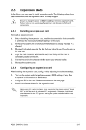
... system and change the necessary BIOS settings, if any. See Chapter 4 for the card. 2. Install the software drivers for later use . Turn on BIOS setup. 2. ASUS Z9NH-D12 Series 2-17 Remove the system unit cover (if your motherboard is completely seated on the slot. 5. Remove the bracket opposite the slot that the cards...
... system and change the necessary BIOS settings, if any. See Chapter 4 for the card. 2. Install the software drivers for later use . Turn on BIOS setup. 2. ASUS Z9NH-D12 Series 2-17 Remove the system unit cover (if your motherboard is completely seated on the slot. 5. Remove the bracket opposite the slot that the cards...
Z9NH-D12 Series User Manual
Page 41
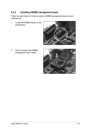
ASUS Z9NH-D12 Series 2-19 Locate the ASMB6 header on your motherboard. 1. Orient and press the ASMB6 management card in place. 2.5.4 Installing ASMB6 management board Follow the steps below to install an optional ASMB6 management board on the motherboard. 2.
ASUS Z9NH-D12 Series 2-19 Locate the ASMB6 header on your motherboard. 1. Orient and press the ASMB6 management card in place. 2.5.4 Installing ASMB6 management board Follow the steps below to install an optional ASMB6 management board on the motherboard. 2.

Z9NH-D12 Series User Manual
Page 43
ASUS Z9NH-D12 Series 2-21 Activity LED indicates Infiniband activity status. 3. Location LED (LOCLED1) This LED allows you to know the server location. 4. Infiniband LED (ACT_LED/ LINK_LED) LINK LED indicates Infiniband link status.
ASUS Z9NH-D12 Series 2-21 Activity LED indicates Infiniband activity status. 3. Location LED (LOCLED1) This LED allows you to know the server location. 4. Infiniband LED (ACT_LED/ LINK_LED) LINK LED indicates Infiniband link status.
Z9NH-D12 Series User Manual
Page 45
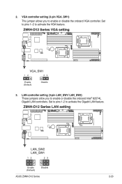
Set to pins 1-2 to activate the VGA feature. 3. VGA controller setting (3-pin VGA_SW1) This jumper allows you to enable or disable the onboard VGA controller. LAN controller setting (3-pin LAN_SW1/ LAN_SW2) These jumpers allow you to enable or disable the onboard Intel® 82574L Gigabit LAN controllers. ASUS Z9NH-D12 Series 2-23 Set to pins 1-2 to activate the Gigabit LAN feature. 2.
Set to pins 1-2 to activate the VGA feature. 3. VGA controller setting (3-pin VGA_SW1) This jumper allows you to enable or disable the onboard VGA controller. LAN controller setting (3-pin LAN_SW1/ LAN_SW2) These jumpers allow you to enable or disable the onboard Intel® 82574L Gigabit LAN controllers. ASUS Z9NH-D12 Series 2-23 Set to pins 1-2 to activate the Gigabit LAN feature. 2.
Z9NH-D12 Series User Manual
Page 47
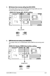
...;D��IM��M�T��R�I�P�1�) This jumper allows you to enable/disable DDR3 DIMM thermal sensing event pin. ASUS Z9NH-D12 Series 2-25
...;D��IM��M�T��R�I�P�1�) This jumper allows you to enable/disable DDR3 DIMM thermal sensing event pin. ASUS Z9NH-D12 Series 2-25
Z9NH-D12 Series User Manual
Page 49
... indicates Infiniband link status. Activity LED indicates Infiniband activity status. 7. This 9-pin communication port is for the DM_LAN1 and LAN port LED indications. 2. ASUS Z9NH-D12 Series 2-27 USB 2.0 ports 1 and 2. This port is for connecting USB 2.0 devices. 4. Serial (COM1) port. Refer to a Local Area...LED indications. 3. Refer to the table on the next page for a VGA monitor or other serial devices. InfiniBand (QSFP). (Z9NH-D12/FDR and Z9NH-D12/10G only) This port allows connection with a QSFP cable to a Local Area Network (LAN) through a network hub. This ...
... indicates Infiniband link status. Activity LED indicates Infiniband activity status. 7. This 9-pin communication port is for the DM_LAN1 and LAN port LED indications. 2. ASUS Z9NH-D12 Series 2-27 USB 2.0 ports 1 and 2. This port is for connecting USB 2.0 devices. 4. Serial (COM1) port. Refer to a Local Area...LED indications. 3. Refer to the table on the next page for a VGA monitor or other serial devices. InfiniBand (QSFP). (Z9NH-D12/FDR and Z9NH-D12/10G only) This port allows connection with a QSFP cable to a Local Area Network (LAN) through a network hub. This ...
Z9NH-D12 Series User Manual
Page 51
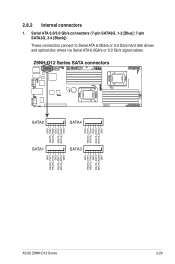
2.8.2 Internal connectors 1. ASUS Z9NH-D12 Series 2-29 Serial ATA 6.0/3.0 Gb/s connectors (7-pin SATA6G_1-2 [Blue]; 7-pin SATA3G_3-4 [Black]) These connectors connect to Serial ATA 6.0Gb/s or 3.0 Gb/s hard disk drives and optical disc drives via Serial ATA 6.0Gb/s or 3.0 Gb/s signal cables.
2.8.2 Internal connectors 1. ASUS Z9NH-D12 Series 2-29 Serial ATA 6.0/3.0 Gb/s connectors (7-pin SATA6G_1-2 [Blue]; 7-pin SATA3G_3-4 [Black]) These connectors connect to Serial ATA 6.0Gb/s or 3.0 Gb/s hard disk drives and optical disc drives via Serial ATA 6.0Gb/s or 3.0 Gb/s signal cables.
Z9NH-D12 Series User Manual
Page 53
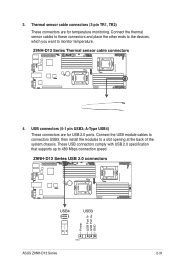
3. Connect the USB module cables to connectors USB3, then install the modules to monitor temperature. 4. ASUS Z9NH-D12 Series 2-31 Connect the thermal sensor cables to these connectors and place the other ends to the devices, which you want to a slot opening at the back of the system chassis. Thermal sensor cable connectors (3-pin TR1, TR2) These connectors are for temperature monitoring. A-Type USB4) These connectors are for USB 2.0 ports. USB connectors (5-1 pin USB3; These USB connectors comply with USB 2.0 specification that supports up to 480 Mbps connection speed.
3. Connect the USB module cables to connectors USB3, then install the modules to monitor temperature. 4. ASUS Z9NH-D12 Series 2-31 Connect the thermal sensor cables to these connectors and place the other ends to the devices, which you want to a slot opening at the back of the system chassis. Thermal sensor cable connectors (3-pin TR1, TR2) These connectors are for temperature monitoring. A-Type USB4) These connectors are for USB 2.0 ports. USB connectors (5-1 pin USB3; These USB connectors comply with USB 2.0 specification that supports up to 480 Mbps connection speed.
Z9NH-D12 Series User Manual
Page 55
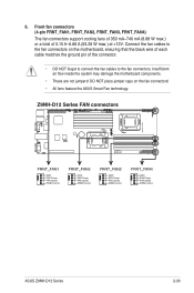
... black wire of each cable matches the ground pin of 3.15 A-6.66 A (53.28 W max.) at +12V. Connect the fan cables to the fan connectors. 6. ASUS Z9NH-D12 Series 2-33 Front fan connectors (4-pin FRNT_FAN1, FRNT_FAN2, FRNT_FAN3, FRNT_FAN4) The fan connectors support cooling fans of 350 mA-740 mA (8.88 W max.) or a total... of the connector. • DO NOT forget to connect the fan cables to the fan connectors on the fan connectors! • All fans feature the ASUS Smart Fan technology.
... black wire of each cable matches the ground pin of 3.15 A-6.66 A (53.28 W max.) at +12V. Connect the fan cables to the fan connectors. 6. ASUS Z9NH-D12 Series 2-33 Front fan connectors (4-pin FRNT_FAN1, FRNT_FAN2, FRNT_FAN3, FRNT_FAN4) The fan connectors support cooling fans of 350 mA-740 mA (8.88 W max.) or a total... of the connector. • DO NOT forget to connect the fan cables to the fan connectors on the fan connectors! • All fans feature the ASUS Smart Fan technology.


