
User Guide
Page 13
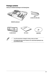
xiii Actual product specifications may vary with different models. Package contents Check your motherboard package for the following items ASUS Z97-E motherboard 2 x Serial ATA 6 Gb/s cables 1 x ASUS I/O Shield User Manual User manual Support DVD • If any of the above items is damaged or missing, contact your retailer. • The illustrated items above are for reference only.
xiii Actual product specifications may vary with different models. Package contents Check your motherboard package for the following items ASUS Z97-E motherboard 2 x Serial ATA 6 Gb/s cables 1 x ASUS I/O Shield User Manual User manual Support DVD • If any of the above items is damaged or missing, contact your retailer. • The illustrated items above are for reference only.

User Guide
Page 15
... transfer speeds of up to two SATA drives of PCIe 2.0. Intel® Z97 Express Chipset Intel® Z97 Express Chipset is the PCI Express bus standard that optimizes PCIe allocation in the LGA1150 package. Z97-E brings you 're never experienced before. It also features backward compatibility with.... It also enables the iGPU function for your computer, allow your system to receive the freshest updates from a deep sleep or hibernate mode. Chapter 1 ASUS Z97-E 1-1 It utilizes the serial point-to six USB 3.0 ports, six SATA 6 Gb/s ports, and M.2 support for the 4th, New 4th & 5th...
... transfer speeds of up to two SATA drives of PCIe 2.0. Intel® Z97 Express Chipset Intel® Z97 Express Chipset is the PCI Express bus standard that optimizes PCIe allocation in the LGA1150 package. Z97-E brings you 're never experienced before. It also features backward compatibility with.... It also enables the iGPU function for your computer, allow your system to receive the freshest updates from a deep sleep or hibernate mode. Chapter 1 ASUS Z97-E 1-1 It utilizes the serial point-to six USB 3.0 ports, six SATA 6 Gb/s ports, and M.2 support for the 4th, New 4th & 5th...
User Guide
Page 17
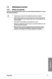
Chapter 1 ASUS Z97-E 1-3 Failure to do so may cause severe damage to avoid touching the ICs on them. • Whenever you uninstall any component, place it on a grounded ...
Chapter 1 ASUS Z97-E 1-3 Failure to do so may cause severe damage to avoid touching the ICs on them. • Whenever you uninstall any component, place it on a grounded ...
User Guide
Page 21
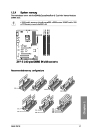
DIMM_A1 DIMM_A2 DIMM_B1 DIMM_B2 1.2.4 System memory The motherboard comes with four DDR 3 (Double Data Rate 3) Dual Inline Memory Modules (DIMM) slots. Z97-E Z97-E 240-pin DDR3 DIMM sockets Recommended memory configurations Chapter 1 ASUS Z97-E 1-7 DO NOT install a DDR or DDR2 memory module to the DDR3 slot. A DDR3 module is notched differently from a DDR or DDR2 module.
DIMM_A1 DIMM_A2 DIMM_B1 DIMM_B2 1.2.4 System memory The motherboard comes with four DDR 3 (Double Data Rate 3) Dual Inline Memory Modules (DIMM) slots. Z97-E Z97-E 240-pin DDR3 DIMM sockets Recommended memory configurations Chapter 1 ASUS Z97-E 1-7 DO NOT install a DDR or DDR2 memory module to the DDR3 slot. A DDR3 module is notched differently from a DDR or DDR2 module.
User Guide
Page 23
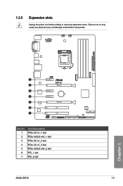
1.2.5 Expansion slots Unplug the power cord before adding or removing expansion cards. Failure to do so may cause you physical injury and damage motherboard components. PCIEX1_1 Z97-E PCIEX16_1 PCIEX1_2 PCIEX1_3 PCIEX16_2 PCI1 PCI2 Slot No. 1 2 3 4 5 6 7 Slot Description PCIe 2.0 x1_1 slot PCIe 3.0/2.0 x16_1 slot PCIe 2.0 x1_2 slot PCIe 2.0 x1_3 slot PCIe 3.0/2.0 x16_2 slot PCI_1 slot PCI_2 slot ASUS Z97-E 1-9 Chapter 1
1.2.5 Expansion slots Unplug the power cord before adding or removing expansion cards. Failure to do so may cause you physical injury and damage motherboard components. PCIEX1_1 Z97-E PCIEX16_1 PCIEX1_2 PCIEX1_3 PCIEX16_2 PCI1 PCI2 Slot No. 1 2 3 4 5 6 7 Slot Description PCIe 2.0 x1_1 slot PCIe 3.0/2.0 x16_1 slot PCIe 2.0 x1_2 slot PCIe 2.0 x1_3 slot PCIe 3.0/2.0 x16_2 slot PCI_1 slot PCI_2 slot ASUS Z97-E 1-9 Chapter 1
User Guide
Page 25
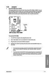
For system failure due to clear the CMOS RTC RAM data. The onboard button cell battery powers the RAM data in CMOS. Z97-E CLRTC +3V_BAT GND PIN 1 Z97-E Clear RTC RAM To erase the RTC RAM: 1. Plug the power cord and turn ON the computer. 4. Shut down the key ...; You do not help, remove the onboard battery and short the two pins again to overclocking, use the CPU Parameter Recall (C.P.R.) feature. Chapter 1 ASUS Z97-E 1-11 Hold down and reboot the system, then the BIOS automatically resets parameter settings to re- Clear RTC RAM (2-pin CLRTC) This jumper allows ...
For system failure due to clear the CMOS RTC RAM data. The onboard button cell battery powers the RAM data in CMOS. Z97-E CLRTC +3V_BAT GND PIN 1 Z97-E Clear RTC RAM To erase the RTC RAM: 1. Plug the power cord and turn ON the computer. 4. Shut down the key ...; You do not help, remove the onboard battery and short the two pins again to overclocking, use the CPU Parameter Recall (C.P.R.) feature. Chapter 1 ASUS Z97-E 1-11 Hold down and reboot the system, then the BIOS automatically resets parameter settings to re- Clear RTC RAM (2-pin CLRTC) This jumper allows ...
User Guide
Page 27
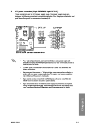
... (PSU) that you are uncertain about the minimum power supply requirement for your system, refer to the Recommended Power Supply Wattage Calculator at http://support.asus. Chapter 1 ASUS Z97-E 1-13 The system may become unstable or may not boot up if the power is inadequate. • If you want to use two or...EATXPWR +12V DC +12V DC +12V DC +12V DC +3 Volts GND +12 Volts +5 Volts +12 Volts +5 Volts +5V Standby +5 Volts Power OK -5 Volts GND GND Z97-E PIN 1 +5 Volts GND GND GND GND GND GND GND +5 Volts PSON# GND GND +3 Volts -12 Volts +3 Volts +3 Volts PIN...
... (PSU) that you are uncertain about the minimum power supply requirement for your system, refer to the Recommended Power Supply Wattage Calculator at http://support.asus. Chapter 1 ASUS Z97-E 1-13 The system may become unstable or may not boot up if the power is inadequate. • If you want to use two or...EATXPWR +12V DC +12V DC +12V DC +12V DC +3 Volts GND +12 Volts +5 Volts +12 Volts +5 Volts +5V Standby +5 Volts Power OK -5 Volts GND GND Z97-E PIN 1 +5 Volts GND GND GND GND GND GND GND +5 Volts PSON# GND GND +3 Volts -12 Volts +3 Volts +3 Volts PIN...
User Guide
Page 29
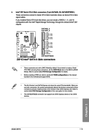
... set to Serial ATA 6 Gb/s hard disk drives via Serial ATA 6 Gb/s signal cables. SATA6G_5 SATA6G_6 Z97-E GND RSATA_TXP5 RSATA_TXN5 GND RSATA_RXP5 RSATA_RXN5 GND GND RSATA_TXP6 RSATA_TXN6 GND RSATA_RXP6 RSATA_RXN6 GND Floating Device_Reset GND Detection SATAEXPRESS... and 10 configuration with the Intel® Rapid Storage Technology through the onboard Intel® Z97 chipset. 4. When you can support one SATA Express device or two SATA devices. Chapter 1 ASUS Z97-E 1-15 Intel® Z97 Serial ATA 6 Gb/s connectors (7-pin SATA6G_56, SATAEXPRESS ) These connectors connect to [AHCI ...
... set to Serial ATA 6 Gb/s hard disk drives via Serial ATA 6 Gb/s signal cables. SATA6G_5 SATA6G_6 Z97-E GND RSATA_TXP5 RSATA_TXN5 GND RSATA_RXP5 RSATA_RXN5 GND GND RSATA_TXP6 RSATA_TXN6 GND RSATA_RXP6 RSATA_RXN6 GND Floating Device_Reset GND Detection SATAEXPRESS... and 10 configuration with the Intel® Rapid Storage Technology through the onboard Intel® Z97 chipset. 4. When you can support one SATA Express device or two SATA devices. Chapter 1 ASUS Z97-E 1-15 Intel® Z97 Serial ATA 6 Gb/s connectors (7-pin SATA6G_56, SATAEXPRESS ) These connectors connect to [AHCI ...
User Guide
Page 31
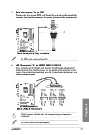
... the USB module cable to any of these connectors, then install the module to a slot opening at the back of the system chassis. COM PIN 1 Z97-E Z97-E Serial port (COM) connector The COM module is purchased separately. Serial port connector (10-1 pin COM) This connector is for USB 2.0 ports. RXD DTR... DSR CTS DCD TXD GND RTS RI 7. ASUS Z97-E 1-17 Chapter 1 USB+5V USB_P9USB_P9+ GND NC USB+5V USB_P11USB_P11+ GND NC USB+5V USB_P13USB_P13+ GND NC USB910 USB1112 USB1314...
... the USB module cable to any of these connectors, then install the module to a slot opening at the back of the system chassis. COM PIN 1 Z97-E Z97-E Serial port (COM) connector The COM module is purchased separately. Serial port connector (10-1 pin COM) This connector is for USB 2.0 ports. RXD DTR... DSR CTS DCD TXD GND RTS RI 7. ASUS Z97-E 1-17 Chapter 1 USB+5V USB_P9USB_P9+ GND NC USB+5V USB_P11USB_P11+ GND NC USB+5V USB_P13USB_P13+ GND NC USB910 USB1112 USB1314...
User Guide
Page 33
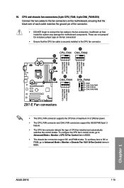
...system may damage the motherboard components. To configure the CPU fan's control mode, go to Advanced Mode > Monitor > CPU Q-Fan Control item in BIOS. Chapter 1 ASUS Z97-E 1-19 To set these fans to DC or PWM, go to Advanced Mode > Monitor > Chassis Fan 1/2/3 Q-Fan Control items in BIOS. • The ...CHA FAN PWM CHA FAN PWM CHA FAN IN CHA FAN PWR GND Z97-E Fan connectors • The CPU_FAN connector supports the CPU fan of maximum 1A (12W) fan power. • The CPU_FAN connector and CHA_FAN connectors support the ASUS FAN Xpert 3 feature. • The CPU fan connector detects the ...
...system may damage the motherboard components. To configure the CPU fan's control mode, go to Advanced Mode > Monitor > CPU Q-Fan Control item in BIOS. Chapter 1 ASUS Z97-E 1-19 To set these fans to DC or PWM, go to Advanced Mode > Monitor > Chassis Fan 1/2/3 Q-Fan Control items in BIOS. • The ...CHA FAN PWM CHA FAN PWM CHA FAN IN CHA FAN PWR GND Z97-E Fan connectors • The CPU_FAN connector supports the CPU fan of maximum 1A (12W) fan power. • The CPU_FAN connector and CHA_FAN connectors support the ASUS FAN Xpert 3 feature. • The CPU fan connector detects the ...
User Guide
Page 35
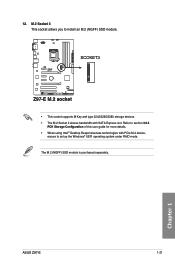
The M.2 (NGFF) SSD module is purchased separately. 12. SCOKET3 Z97-E Z97-E M.2 socket • This socket supports M Key and type 2242/2260/2280 storage devices. • The M.2 Socket 3 shares bandwidth with PCIe M.2 device, ensure to set up the Windows® UEFI operating system under RAID mode. Refer to install an M.2 (NGFF) SSD module. Chapter 1 ASUS Z97-E 1-21 M.2 Socket 3 This socket allows you to section 3.6.3 PCH Storage Configuration of this user guide for more details. • When using Intel® Desktop Responsiveness technologies with SATA Express slot.
The M.2 (NGFF) SSD module is purchased separately. 12. SCOKET3 Z97-E Z97-E M.2 socket • This socket supports M Key and type 2242/2260/2280 storage devices. • The M.2 Socket 3 shares bandwidth with PCIe M.2 device, ensure to set up the Windows® UEFI operating system under RAID mode. Refer to install an M.2 (NGFF) SSD module. Chapter 1 ASUS Z97-E 1-21 M.2 Socket 3 This socket allows you to section 3.6.3 PCH Storage Configuration of this user guide for more details. • When using Intel® Desktop Responsiveness technologies with SATA Express slot.
User Guide
Page 37
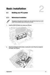
Chapter 2 ASUS Z97-E 2-1 Install the ASUS I/O-Shield to the chassis' rear I /O panel. 2. The motherboard layout may vary with models, but the installation steps are the same for reference only. Chapter 2: Basic installation Basic installation 2.1 Building your PC system 2 2.1.1 Motherboard installation The diagrams in this section are for all models. 1. Place the motherboard into the chassis, ensuring that its rear I/O ports are aligned to the chassis rear I /O panel.
Chapter 2 ASUS Z97-E 2-1 Install the ASUS I/O-Shield to the chassis' rear I /O panel. 2. The motherboard layout may vary with models, but the installation steps are the same for reference only. Chapter 2: Basic installation Basic installation 2.1 Building your PC system 2 2.1.1 Motherboard installation The diagrams in this section are for all models. 1. Place the motherboard into the chassis, ensuring that its rear I/O ports are aligned to the chassis rear I /O panel.
User Guide
Page 39
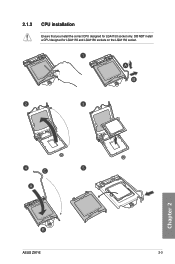
Chapter 2 ASUS Z97-E 2-3 DO NOT install a CPU designed for LGA1150 socket only. 2.1.2 CPU installation Ensure that you install the correct CPU designed for LGA1155 and LGA1156 sockets on the LGA1150 socket.
Chapter 2 ASUS Z97-E 2-3 DO NOT install a CPU designed for LGA1150 socket only. 2.1.2 CPU installation Ensure that you install the correct CPU designed for LGA1155 and LGA1156 sockets on the LGA1150 socket.
User Guide
Page 41
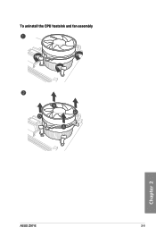
To uninstall the CPU heatsink and fan assembly Chapter 2 ASUS Z97-E 2-5
To uninstall the CPU heatsink and fan assembly Chapter 2 ASUS Z97-E 2-5
User Guide
Page 43
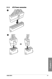
2.1.5 ATX Power connection OR ASUS Z97-E 2-7 Chapter 2
2.1.5 ATX Power connection OR ASUS Z97-E 2-7 Chapter 2
User Guide
Page 47
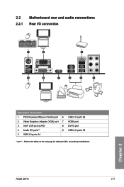
USB 3.0 ports 56 2. USB 3.0 ports 34 * and **: Refer to the tables on the next page for LAN port LEDs, and audio port definitions. HDMI port 3. USB 2.0 ports 78 5. Video Graphics Adapter (VGA) port 7. Audio I /O connection 1 2 3 9 8 7 6 5 4 Rear panel connectors 1. DVI-D port 4. Intel® LAN port (LAN)* 8. Chapter 2 ASUS Z97-E 2-11 2.2 Motherboard rear and audio connections 2.2.1 Rear I /O ports** 9. PS/2 Keyboard/Mouse Combo port 6.
USB 3.0 ports 56 2. USB 3.0 ports 34 * and **: Refer to the tables on the next page for LAN port LEDs, and audio port definitions. HDMI port 3. USB 2.0 ports 78 5. Video Graphics Adapter (VGA) port 7. Audio I /O connection 1 2 3 9 8 7 6 5 4 Rear panel connectors 1. DVI-D port 4. Intel® LAN port (LAN)* 8. Chapter 2 ASUS Z97-E 2-11 2.2 Motherboard rear and audio connections 2.2.1 Rear I /O ports** 9. PS/2 Keyboard/Mouse Combo port 6.
User Guide
Page 49
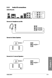
2.2.2 Audio I/O connections Audio I/O ports Connect to Headphone and Mic Connect to Stereo Speakers Chapter 2 Connect to 2.1 channel Speakers ASUS Z97-E 2-13
2.2.2 Audio I/O connections Audio I/O ports Connect to Headphone and Mic Connect to Stereo Speakers Chapter 2 Connect to 2.1 channel Speakers ASUS Z97-E 2-13
User Guide
Page 51
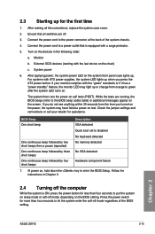
... the time you press the ATX power button. At power on the BIOS setting. Ensure that is ON, press the power button for assistance. Chapter 2 ASUS Z97-E 2-15 Monitor b. If your retailer for less than four seconds to let the system enter the soft-off mode regardless of the system chassis. 4. Connect...
... the time you press the ATX power button. At power on the BIOS setting. Ensure that is ON, press the power button for assistance. Chapter 2 ASUS Z97-E 2-15 Monitor b. If your retailer for less than four seconds to let the system enter the soft-off mode regardless of the system chassis. 4. Connect...

User Guide
Page 53
...failure. Inappropriate BIOS settings may result to "UEFI BIOS" unless otherwise specified. Chapter 3: BIOS setup BIOS setup 3.1 Knowing BIOS 3 The new ASUS UEFI BIOS is a Unified Extensible Interface that complies with UEFI architecture, offering a user-friendly interface that goes beyond the traditional keyboardonly BIOS controls... appears on the screen during the system bootup and requests you to enable a more flexible and convenient mouse input. Chapter 3 ASUS Z97-E 3-1 In normal circumstances, the default BIOS settings apply to most conditions to ensure optimal performance.
...failure. Inappropriate BIOS settings may result to "UEFI BIOS" unless otherwise specified. Chapter 3: BIOS setup BIOS setup 3.1 Knowing BIOS 3 The new ASUS UEFI BIOS is a Unified Extensible Interface that complies with UEFI architecture, offering a user-friendly interface that goes beyond the traditional keyboardonly BIOS controls... appears on the screen during the system bootup and requests you to enable a more flexible and convenient mouse input. Chapter 3 ASUS Z97-E 3-1 In normal circumstances, the default BIOS settings apply to most conditions to ensure optimal performance.
User Guide
Page 55
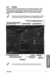
... the display language Creates storage RAID and of the BIOS setup program configures system overclocking Chapter 3 Enables or disables the SATA RAID mode for details. ASUS Z97-E 3-3 Click < or > to the Setup Mode item in section 3.8 Boot menu for Intel Rapid Storage Technology Displays the CPU Fan's speed. The EZ Mode provides...
... the display language Creates storage RAID and of the BIOS setup program configures system overclocking Chapter 3 Enables or disables the SATA RAID mode for details. ASUS Z97-E 3-3 Click < or > to the Setup Mode item in section 3.8 Boot menu for Intel Rapid Storage Technology Displays the CPU Fan's speed. The EZ Mode provides...


