User Guide
Page 4
... model only 2-20 2.5.9 Installing an ASUS PIKE RAID card (Z8NA-D6 model only 2-21 2.5.10 Installing i Button (Z8NA-D6 model only 2-22 2.5.11 Installing ASMB4 management board (Z8NA-D6 model only 2-22 2.5.12 Installing the audio card 2-23 2.5.13 Connect Thermal sensor cable 2-23 2.6 Jumpers 2-24 2.7 Connectors 2-29 2.7.1 Rear panel connectors 2-29 2.7.2 Internal connectors 2-30 Chapter 3: Powering up...
... model only 2-20 2.5.9 Installing an ASUS PIKE RAID card (Z8NA-D6 model only 2-21 2.5.10 Installing i Button (Z8NA-D6 model only 2-22 2.5.11 Installing ASMB4 management board (Z8NA-D6 model only 2-22 2.5.12 Installing the audio card 2-23 2.5.13 Connect Thermal sensor cable 2-23 2.6 Jumpers 2-24 2.7 Connectors 2-29 2.7.1 Rear panel connectors 2-29 2.7.2 Internal connectors 2-30 Chapter 3: Powering up...
User Guide
Page 28
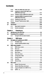
...10 2-15 2-20 2-20 2-20 2-20 2-20 Jumpers 1. Clear RTC RAM (CLRTC1) 2. Intel® ICH10R SATA port S/W RAID setting (3-pin RAID_SEL1) (Z8NA-D6 model only) 6. PS/2 mouse port (green) 2. LAN 2 (RJ-45) port Page 2-29 2-29 2-29 2-29 2-29 2-29 2-29 2-8...setting (3-pin RECOVERY1) Page 2-24 2-25 2-25 2-26 2-26 2-27 2-27 2-28 Rear panel connectors 1. PCI Express x8 slots (x4 link) 5. Serial (COM1) port 5. USB 2.0 ports 1 and 2 4. iBTN RAID setting (3-pin IBTN_SEL1) (Z8NA-D6 model only) 7. LAN 1 (RJ-45) port 7. 2.2.4 Layout contents Slots/Soocket 1. PCI...
...10 2-15 2-20 2-20 2-20 2-20 2-20 Jumpers 1. Clear RTC RAM (CLRTC1) 2. Intel® ICH10R SATA port S/W RAID setting (3-pin RAID_SEL1) (Z8NA-D6 model only) 6. PS/2 mouse port (green) 2. LAN 2 (RJ-45) port Page 2-29 2-29 2-29 2-29 2-29 2-29 2-29 2-8...setting (3-pin RECOVERY1) Page 2-24 2-25 2-25 2-26 2-26 2-27 2-27 2-28 Rear panel connectors 1. PCI Express x8 slots (x4 link) 5. Serial (COM1) port 5. USB 2.0 ports 1 and 2 4. iBTN RAID setting (3-pin IBTN_SEL1) (Z8NA-D6 model only) 7. LAN 1 (RJ-45) port 7. 2.2.4 Layout contents Slots/Soocket 1. PCI...

User Guide
Page 49
... LAN port LED indications. 7. LAN 1 (RJ-45) port. PS/2 keyboard port (purple). Refer to the table below for a VGA monitor or other serial devices. 5. 2.7 Connectors 2.7.1 Rear panel connectors 1. PS/2 mouse port (green). This port is for the LAN port LED indications. Serial (COM1) port. This port is for connecting USB 2.0 devices. 4. LAN port... BLINKING Data activity Speed LED Status Description OFF 10 Mbps connection ORANGE 100 Mbps connection GREEN 1 Gbps connection ACT/LINK SPEED LED LED LAN port ASUS Z8NA-D6 Series 2-29
... LAN port LED indications. 7. LAN 1 (RJ-45) port. PS/2 keyboard port (purple). Refer to the table below for a VGA monitor or other serial devices. 5. 2.7 Connectors 2.7.1 Rear panel connectors 1. PS/2 mouse port (green). This port is for the LAN port LED indications. Serial (COM1) port. This port is for connecting USB 2.0 devices. 4. LAN port... BLINKING Data activity Speed LED Status Description OFF 10 Mbps connection ORANGE 100 Mbps connection GREEN 1 Gbps connection ACT/LINK SPEED LED LED LAN port ASUS Z8NA-D6 Series 2-29

User Guide
Page 50
... for Serial ATA hard disk drives that allows up . 2-30 Chapter 2: Hardware information 2.7.2 Internal connectors 1. Black) Supported by the Intel® ICH10R chipset, these connectors are for the Serial ATA signal cables for the storage add-on the speed of Serial ATA hard disks installed. 2. If you installed Serial ATA ... depends on card cable connected to light up to 3Gb/s of any device connected to the SATA or SAS add-on card causes the front panel LED to the SATA or SAS add-on card. Serial ATA connectors (7-pin SATA1, SATA2, SATA3, SATA4; RED) (7-pin SATA5, SATA6;
... for Serial ATA hard disk drives that allows up . 2-30 Chapter 2: Hardware information 2.7.2 Internal connectors 1. Black) Supported by the Intel® ICH10R chipset, these connectors are for the Serial ATA signal cables for the storage add-on the speed of Serial ATA hard disks installed. 2. If you installed Serial ATA ... depends on card cable connected to light up to 3Gb/s of any device connected to the SATA or SAS add-on card causes the front panel LED to the SATA or SAS add-on card. Serial ATA connectors (7-pin SATA1, SATA2, SATA3, SATA4; RED) (7-pin SATA5, SATA6;

User Guide
Page 57
...system power LED. Hard disk drive activity LED (2-pin HDDLED) This 2-pin connector is controlled by Hardware monitor to this connector. Message LED (2-pin MLED) This 2-pin connector is for the HDD Activity LED. ASUS Z8NA-D6 Series 2-37 The system power LED lights up or flashes when data... ATX power button/soft-off the system power. Pressing the power button turns the system on the BIOS settings. The IDE LED lights up when you to the front message LED. System warning speaker (4-pin SPEAKER) This 4-pin connector is ON turns the system OFF. 6. 13. System panel connector ...
...system power LED. Hard disk drive activity LED (2-pin HDDLED) This 2-pin connector is controlled by Hardware monitor to this connector. Message LED (2-pin MLED) This 2-pin connector is for the HDD Activity LED. ASUS Z8NA-D6 Series 2-37 The system power LED lights up or flashes when data... ATX power button/soft-off the system power. Pressing the power button turns the system on the BIOS settings. The IDE LED lights up when you to the front message LED. System warning speaker (4-pin SPEAKER) This 4-pin connector is ON turns the system OFF. 6. 13. System panel connector ...

User Guide
Page 58
... to these leads to record a chassis intrusion event. 14. Auxiliary panel connector (20-pin AUX_PANEL1) This connector is pressed. 5. The LEDs will light up when the Locator button is for additional front panel features including front panel SMB, locator LED and switch, chassis intrusion, and LAN LEDs. ...These leads are for Gigabit LAN activity LEDs on the front panel. The default setting is short CASEOPEN and GND pin by jumper cap to these 2-pin connector. Front panel SMB (6-1 pin FPSMB) These leads connect the front panel SMBus cable. 2. This button queries the state of the...
... to these leads to record a chassis intrusion event. 14. Auxiliary panel connector (20-pin AUX_PANEL1) This connector is pressed. 5. The LEDs will light up when the Locator button is for additional front panel features including front panel SMB, locator LED and switch, chassis intrusion, and LAN LEDs. ...These leads are for Gigabit LAN activity LEDs on the front panel. The default setting is short CASEOPEN and GND pin by jumper cap to these 2-pin connector. Front panel SMB (6-1 pin FPSMB) These leads connect the front panel SMBus cable. 2. This button queries the state of the...

User Guide
Page 61
... call your monitor complies with the last device on self-test or POST. ASUS Z8NA-D6 Series 3-3 Follow the instructions in the following order: a. External SCSI devices... time you press the ATX power button. After applying power, the system power LED on the system front panel case lights up or ...connector at the back of the system chassis. 4. Turn on , hold down the key to a power outlet that all the connections, replace the system case cover. 2. For systems with a surge protector. 5. The system then runs the power-on the chain) c. Ensure that is equipped with ATX...
... call your monitor complies with the last device on self-test or POST. ASUS Z8NA-D6 Series 3-3 Follow the instructions in the following order: a. External SCSI devices... time you press the ATX power button. After applying power, the system power LED on the system front panel case lights up or ...connector at the back of the system chassis. 4. Turn on , hold down the key to a power outlet that all the connections, replace the system case cover. 2. For systems with a surge protector. 5. The system then runs the power-on the chain) c. Ensure that is equipped with ATX...


