User Guide
Page 11
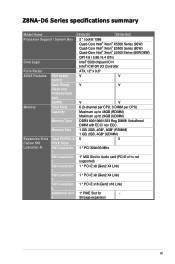
... Z8NA-D6C Processor Support / System Bus 2 * socket 1366 Quad-Core Intel® Xeon® X5500 Series (95W) Quad-Core Intel® Xeon® E5500 Series (80W) Quad-Core Intel® Xeon® L5500 Series (60W/38W) Core Logic QPI 4.8 / 5.86 / 6.4 GT/s Intel® 5500 chipset I/O H Intel® ICH10R I/O Controller Form Factor ATX, 12" x 9.6" ASUS...
... Z8NA-D6C Processor Support / System Bus 2 * socket 1366 Quad-Core Intel® Xeon® X5500 Series (95W) Quad-Core Intel® Xeon® E5500 Series (80W) Quad-Core Intel® Xeon® L5500 Series (60W/38W) Core Logic QPI 4.8 / 5.86 / 6.4 GT/s Intel® 5500 chipset I/O H Intel® ICH10R I/O Controller Form Factor ATX, 12" x 9.6" ASUS...
User Guide
Page 12
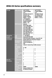
... 6480 8-port SAS RAID card 2 * Intel 82574L Aspeed AST2050 8MB 24-pin ATX power connector + 8-pin ATX 12V (Support Both ATX & SSI Power Supply)** Onboard header for KVM-over-Internet 1 2 1 ASWM - ASUS PIKE 1064E 4-port SAS RAID card; Z8NA-D6 Series specifications summary Storage Networking Graphic Onboard I/O Connectors Rear I/O Connectors SATA Controller SAS Controller LAN...
... 6480 8-port SAS RAID card 2 * Intel 82574L Aspeed AST2050 8MB 24-pin ATX power connector + 8-pin ATX 12V (Support Both ATX & SSI Power Supply)** Onboard header for KVM-over-Internet 1 2 1 ASWM - ASUS PIKE 1064E 4-port SAS RAID card; Z8NA-D6 Series specifications summary Storage Networking Graphic Onboard I/O Connectors Rear I/O Connectors SATA Controller SAS Controller LAN...
User Guide
Page 13
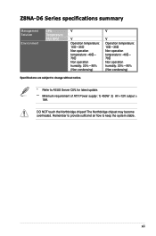
Remember to provide sufficinet air flow to ASUS Server QVL for latest update. ** Minimum requirement of ATX Power supply: 1) 450W 2) All +12V output ≥ 18A. DO NOT touch the Northbridge chipset! xiii The Northbridge chipset may become overheated. Z8NA-D6 Series specifications summary Management Solution Environment CPU Temperature FAN RPM V V V Operation temperature: 10℃...
Remember to provide sufficinet air flow to ASUS Server QVL for latest update. ** Minimum requirement of ATX Power supply: 1) 450W 2) All +12V output ≥ 18A. DO NOT touch the Northbridge chipset! xiii The Northbridge chipset may become overheated. Z8NA-D6 Series specifications summary Management Solution Environment CPU Temperature FAN RPM V V V Operation temperature: 10℃...
User Guide
Page 25
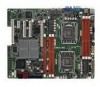
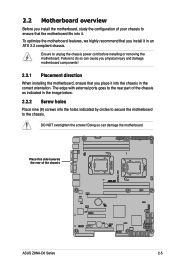
...motherboard. Failure to do so can damage the motherboard. Doing so can cause you physical injury and damage motherboard components! 2.2.1 Placement direction When installing the motherboard, ensure that the motherboard fits into it. The edge with external ports goes to the rear part of the chassis ASUS Z8NA...circles to secure the motherboard to the chassis. 2.2 Motherboard overview Before you install the motherboard, study the configuration of your chassis to ensure that you place it into the chassis in the correct orientation. To optimize the motherboard features, we highly ...
...motherboard. Failure to do so can damage the motherboard. Doing so can cause you physical injury and damage motherboard components! 2.2.1 Placement direction When installing the motherboard, ensure that the motherboard fits into it. The edge with external ports goes to the rear part of the chassis ASUS Z8NA...circles to secure the motherboard to the chassis. 2.2 Motherboard overview Before you install the motherboard, study the configuration of your chassis to ensure that you place it into the chassis in the correct orientation. To optimize the motherboard features, we highly ...

User Guide
Page 56
... proper orientation and push down firmly until the connectors completely fit. • DO NOT forget to fit these connectors in only one orientation. ATX power connectors (24-pin ATXPWR1, 8-pin ATX12V1) These connectors are designed to connect the 24+8-pin power plugs; The power supply plugs are... for an SSI & ATX power supply plugs. otherwise, the system will not boot up if the power is recommended when configuring a system with a higher power output is inadequate...
... proper orientation and push down firmly until the connectors completely fit. • DO NOT forget to fit these connectors in only one orientation. ATX power connectors (24-pin ATXPWR1, 8-pin ATX12V1) These connectors are designed to connect the 24+8-pin power plugs; The power supply plugs are... for an SSI & ATX power supply plugs. otherwise, the system will not boot up if the power is recommended when configuring a system with a higher power output is inadequate...

User Guide
Page 57
... connector is controlled by Hardware monitor to hear system beeps and warnings. 4. ATX power button/soft-off mode depending on or puts the system in sleep or soft-off button (2-pin PWRSW) This connector is in sleep mode. 2. ASUS Z8NA-D6 Series 2-37 System panel connector (20-pin PANEL1) This connector supports several...
... connector is controlled by Hardware monitor to hear system beeps and warnings. 4. ATX power button/soft-off mode depending on or puts the system in sleep or soft-off button (2-pin PWRSW) This connector is in sleep mode. 2. ASUS Z8NA-D6 Series 2-37 System panel connector (20-pin PANEL1) This connector supports several...

User Guide
Page 61
... the power cord to a power outlet that all the connections, replace the system case cover. 2. System power 6. Ensure that is equipped with ATX power supplies, the system LED lights up . After applying power, the system power LED on the system front panel case lights up when you turned...c. After making all switches are running, the BIOS beeps or additional messages appear on the screen. Turn on the devices in Chapter 4. ASUS Z8NA-D6 Series 3-3 If your retailer for the first time 1. 3.1 Starting up or switch between orange and green after the system LED turns on.
... the power cord to a power outlet that all the connections, replace the system case cover. 2. System power 6. Ensure that is equipped with ATX power supplies, the system LED lights up . After applying power, the system power LED on the system front panel case lights up when you turned...c. After making all switches are running, the BIOS beeps or additional messages appear on the screen. Turn on the devices in Chapter 4. ASUS Z8NA-D6 Series 3-3 If your retailer for the first time 1. 3.1 Starting up or switch between orange and green after the system LED turns on.

