
User Guide
Page 14
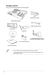
Actual product specifications may vary with different models. xiv Package contents Check your motherboard package for the following items ASUS X99-PRO motherboard 6 x Serial ATA 6 Gb/s cables 1 x ASUS Q-Shield 1 x ASUS SLI™ bridge connector HYPER M.2 x 4 Support DVD User Manual 1 x ASUS 2T2R dual-band Wi-Fi moving antennas (Wi-Fi 802.11a/b/g/n/ac compliant) 1 x 2-in-1 ASUS Q-Connector kit Technical documentations • If any of the above items is damaged or missing, contact your retailer. • The illustrated items above are for reference only.
Actual product specifications may vary with different models. xiv Package contents Check your motherboard package for the following items ASUS X99-PRO motherboard 6 x Serial ATA 6 Gb/s cables 1 x ASUS Q-Shield 1 x ASUS SLI™ bridge connector HYPER M.2 x 4 Support DVD User Manual 1 x ASUS 2T2R dual-band Wi-Fi moving antennas (Wi-Fi 802.11a/b/g/n/ac compliant) 1 x 2-in-1 ASUS Q-Connector kit Technical documentations • If any of the above items is damaged or missing, contact your retailer. • The illustrated items above are for reference only.

User Guide
Page 17
... play games at 4K and beyond. It provides great system performance, quad-channel DDR4 memory slots and PCI Express 2.0/3.0 expansion slots. Intel® X99 Express Chipset Intel® X99 Express Chipset is a single chipset that supports the LGA2011-v3 socket for Intel® Core™ i7 processors This motherboard supports the New... features backward compatibility with up with PCI Express 3.0 x4 slot to speed up data transfer up to meet the higher bandwidth requirements of PCIe 2.0. Chapter 1 ASUS X99-PRO 1-1
... play games at 4K and beyond. It provides great system performance, quad-channel DDR4 memory slots and PCI Express 2.0/3.0 expansion slots. Intel® X99 Express Chipset Intel® X99 Express Chipset is a single chipset that supports the LGA2011-v3 socket for Intel® Core™ i7 processors This motherboard supports the New... features backward compatibility with up with PCI Express 3.0 x4 slot to speed up data transfer up to meet the higher bandwidth requirements of PCIe 2.0. Chapter 1 ASUS X99-PRO 1-1

User Guide
Page 19
... the power supply case, to avoid damaging them due to static electricity. • Hold components by the edges to the motherboard, peripherals, or components. Chapter 1 ASUS X99-PRO 1-3 1.2 Motherboard overview 1.2.1 Before you proceed Take note of the following precautions before you install or remove any component, ensure that the ATX power supply is...
... the power supply case, to avoid damaging them due to static electricity. • Hold components by the edges to the motherboard, peripherals, or components. Chapter 1 ASUS X99-PRO 1-3 1.2 Motherboard overview 1.2.1 Before you proceed Take note of the following precautions before you install or remove any component, ensure that the ATX power supply is...

User Guide
Page 21
... 1-7 1-33 1-6 1-34 1-17 1-29 1-31 1-19 1-30 1-18 1-37 1-38 1-35 1-36 1-32 1-20 1-21 1-36 1-25 1-16 1-16 1-38 1-39 1-30 1-22 1-37 Chapter 1 ASUS X99-PRO 1-5 USB 3.0 connectors (20-1 pin USB3_12, USB3_34) 8. EZ XMP switch 17.
... 1-7 1-33 1-6 1-34 1-17 1-29 1-31 1-19 1-30 1-18 1-37 1-38 1-35 1-36 1-32 1-20 1-21 1-36 1-25 1-16 1-16 1-38 1-39 1-30 1-22 1-37 Chapter 1 ASUS X99-PRO 1-5 USB 3.0 connectors (20-1 pin USB3_12, USB3_34) 8. EZ XMP switch 17.

User Guide
Page 23
A DDR4 module is notched differently from a DDR, DDR2, or DDR3 module. Recommended memory configurations Chapter 1 ASUS X99-PRO 1-7 DO NOT install a DDR, DDR2, or DDR3 memory module to the DDR4 slot. 1.2.4 System memory The motherboard comes with eight DDR 4 (Double Data Rate 4) Quad Inline Memory Modules (DIMM) slots.
A DDR4 module is notched differently from a DDR, DDR2, or DDR3 module. Recommended memory configurations Chapter 1 ASUS X99-PRO 1-7 DO NOT install a DDR, DDR2, or DDR3 memory module to the DDR4 slot. 1.2.4 System memory The motherboard comes with eight DDR 4 (Double Data Rate 4) Quad Inline Memory Modules (DIMM) slots.

User Guide
Page 25
...8226; 1.2V • • 1.2V • • 1.2V • • 1.2V • • Chapter 1 ASUS X99-PRO 1-9 Size SS/ Chip Chip NO. CORSAIR CORSAIR CORSAIR CORSAIR CORSAIR CORSAIR G.SKILL G.SKILL CMD16GX4M4A2666C14 CMD32GX4M4A2666C14 CMK16GX4M4A2666C15 CMK32GX4M4A2666C15 CMK16GX4M4A2666C14R CMK32GX4M4A2666C14R F4-2666C15Q-16GRR F4...16GB (4GBx4) SS 32GB (8GBx4) DS Chip Chip Brand NO. - - - - - - - - - - - - X99-PRO Motherboard Qualified Vendors Lists (QVL) DDR4 3000 (O.C.) MHz capability Vendors Part No. G.SKILL G.SKILL G.SKILL F4-3000C16Q-32GRR F4-3000C15Q...
...8226; 1.2V • • 1.2V • • 1.2V • • 1.2V • • Chapter 1 ASUS X99-PRO 1-9 Size SS/ Chip Chip NO. CORSAIR CORSAIR CORSAIR CORSAIR CORSAIR CORSAIR G.SKILL G.SKILL CMD16GX4M4A2666C14 CMD32GX4M4A2666C14 CMK16GX4M4A2666C15 CMK32GX4M4A2666C15 CMK16GX4M4A2666C14R CMK32GX4M4A2666C14R F4-2666C15Q-16GRR F4...16GB (4GBx4) SS 32GB (8GBx4) DS Chip Chip Brand NO. - - - - - - - - - - - - X99-PRO Motherboard Qualified Vendors Lists (QVL) DDR4 3000 (O.C.) MHz capability Vendors Part No. G.SKILL G.SKILL G.SKILL F4-3000C16Q-32GRR F4-3000C15Q...

User Guide
Page 29
Failure to do so may cause you physical injury and damage motherboard components. 1.2.5 Expansion slots Unplug the power cord before adding or removing expansion cards. Chapter 1 Slot No. 1 2 3 4 5 6 40-LANE PCIe 3.0/2.0 x16_1 slot PCIe 2.0 x1_1 slot PCIe 2.0 x16_2 slot PCIe 3.0/2.0 x16_3 slot PCIe 2.0 x1_2 slot PCIe 3.0/2.0 x16_4 slot Slot Description 28-LANE PCIe 3.0/2.0 x16_1 slot PCIe 2.0 x1_1 slot PCIe 2.0 x16_2 slot PCIe 3.0/2.0 x16_3 slot PCIe 2.0 x1_2 slot PCIe 3.0/2.0 x16_4 slot ASUS X99-PRO 1-13
Failure to do so may cause you physical injury and damage motherboard components. 1.2.5 Expansion slots Unplug the power cord before adding or removing expansion cards. Chapter 1 Slot No. 1 2 3 4 5 6 40-LANE PCIe 3.0/2.0 x16_1 slot PCIe 2.0 x1_1 slot PCIe 2.0 x16_2 slot PCIe 3.0/2.0 x16_3 slot PCIe 2.0 x1_2 slot PCIe 3.0/2.0 x16_4 slot Slot Description 28-LANE PCIe 3.0/2.0 x16_1 slot PCIe 2.0 x1_1 slot PCIe 2.0 x16_2 slot PCIe 3.0/2.0 x16_3 slot PCIe 2.0 x1_2 slot PCIe 3.0/2.0 x16_4 slot ASUS X99-PRO 1-13
User Guide
Page 31
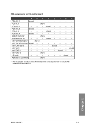
shared* - - - - Intel® LAN1 (i218) - - - - shared - - PCIe x1_1 - - PCIe x1_2 - - - Intel® xHCI - - - - - - - Intel® EHCI 2 - - shared - - - - - Chapter 1 ASUS X99-PRO 1-15 shared - - - - - PCIe x16_4 shared - - - - - - - shared - - - - - HD Audio - - - - - - When the bandwidth is set to A. SMBUS Controller - - Intel® SATA Controller 1 - ASMedia U3 Controller - - Wi-Fi/...
shared* - - - - Intel® LAN1 (i218) - - - - shared - - PCIe x1_1 - - PCIe x1_2 - - - Intel® xHCI - - - - - - - Intel® EHCI 2 - - shared - - - - - Chapter 1 ASUS X99-PRO 1-15 shared - - - - - PCIe x16_4 shared - - - - - - - shared - - - - - HD Audio - - - - - - When the bandwidth is set to A. SMBUS Controller - - Intel® SATA Controller 1 - ASMedia U3 Controller - - Wi-Fi/...
User Guide
Page 33
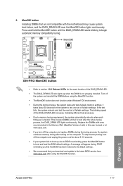
...• We recommend that are not compatible with ones recommended in the Memory QVL (Qualified Vendors Lists) in this user manual or at www.asus.com. • If you download and update to BIOS overclocking, press the MemOK! button to boot up when the DIMM is tested. A...process, the DIAG_DRAM LED lights continuously. button Installing DIMMs that you turn off the system and reinstall the DIMM before using the MemOK! ASUS X99-PRO 1-17 Chapter 1 Turn off the computer and unplug the power cord for about 30 seconds for the exact location of failsafe settings. If...
...• We recommend that are not compatible with ones recommended in the Memory QVL (Qualified Vendors Lists) in this user manual or at www.asus.com. • If you download and update to BIOS overclocking, press the MemOK! button to boot up when the DIMM is tested. A...process, the DIAG_DRAM LED lights continuously. button Installing DIMMs that you turn off the system and reinstall the DIMM before using the MemOK! ASUS X99-PRO 1-17 Chapter 1 Turn off the computer and unplug the power cord for about 30 seconds for the exact location of failsafe settings. If...

User Guide
Page 35
Chapter 1 ASUS X99-PRO 1-19 Enable this switch when the system is powered off. • The EPU LED (O2LED3) near the EPU switch lights up when you have made. 5. ...
Chapter 1 ASUS X99-PRO 1-19 Enable this switch when the system is powered off. • The EPU LED (O2LED3) near the EPU switch lights up when you have made. 5. ...
User Guide
Page 37
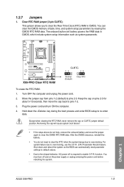
... and enter BIOS setup to clear the Real Time Clock (RTC) RAM in CMOS, which include system setup information such as system passwords. 1.2.7 Jumpers 1. function. ASUS X99-PRO 1-21 Chapter 1 Clear RTC RAM jumper (3-pin CLRTC) This jumper allows you to re-enter data. Turn OFF the computer and unplug the power cord...
... and enter BIOS setup to clear the Real Time Clock (RTC) RAM in CMOS, which include system setup information such as system passwords. 1.2.7 Jumpers 1. function. ASUS X99-PRO 1-21 Chapter 1 Clear RTC RAM jumper (3-pin CLRTC) This jumper allows you to re-enter data. Turn OFF the computer and unplug the power cord...

User Guide
Page 39
POST State LEDs The POST State LEDs provide the status of these key components during POST (Power-On-Self Test): CPU, memory modules, VGA card, and hard disk drives. TPU LED (TPU_LED) The TPU LED lights up until the problem is enabled. 1.2.8 Onboard LEDs 1. Chapter 1 ASUS X99-PRO 1-23 If an error is found, the critical component's LED stays lit up when the TPU switch is solved. 2.
POST State LEDs The POST State LEDs provide the status of these key components during POST (Power-On-Self Test): CPU, memory modules, VGA card, and hard disk drives. TPU LED (TPU_LED) The TPU LED lights up until the problem is enabled. 1.2.8 Onboard LEDs 1. Chapter 1 ASUS X99-PRO 1-23 If an error is found, the critical component's LED stays lit up when the TPU switch is solved. 2.

User Guide
Page 41
Refer to the Q-Code table on the next page) ASUS X99-PRO 1-25 Chapter 1 Q-Code LEDs The Q-Code LED design provides you with a 2-digit error code that displays the system status. Q-Code table Code 00 02 03 ...
Refer to the Q-Code table on the next page) ASUS X99-PRO 1-25 Chapter 1 Q-Code LEDs The Q-Code LED design provides you with a 2-digit error code that displays the system status. Q-Code table Code 00 02 03 ...

User Guide
Page 43
... CPU initialization error System Agent initialization error PCH initialization error Some of NVRAM settings) Reserved for Legacy Option ROM (continued on the next page) Chapter 1 ASUS X99-PRO 1-27 BF D0 D1 D2 D3 D4 D5 Description PCI Bus Enumeration PCI Bus Request Resources PCI Bus Assign Resources Console Output devices connect Console...
... CPU initialization error System Agent initialization error PCH initialization error Some of NVRAM settings) Reserved for Legacy Option ROM (continued on the next page) Chapter 1 ASUS X99-PRO 1-27 BF D0 D1 D2 D3 D4 D5 Description PCI Bus Enumeration PCI Bus Request Resources PCI Bus Assign Resources Console Output devices connect Console...
User Guide
Page 45
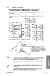
... support DVD. • The SATAEXPRESS_1 connector can create a RAID 0, 1, 5, and 10 configuration with the Intel® Rapid Storage Technology through the onboard Intel® X99 chipset. ASUS X99-PRO 1-29 1.2.9 Internal connectors 1. If you installed Serial ATA hard disk drives, you intend to create a Serial ATA RAID set using these connectors, set to Serial...
... support DVD. • The SATAEXPRESS_1 connector can create a RAID 0, 1, 5, and 10 configuration with the Intel® Rapid Storage Technology through the onboard Intel® X99 chipset. ASUS X99-PRO 1-29 1.2.9 Internal connectors 1. If you installed Serial ATA hard disk drives, you intend to create a Serial ATA RAID set using these connectors, set to Serial...

User Guide
Page 47
... rear panel ports. 4. With an installed USB 3.0 module, you to connect a USB 3.0 module for USB-chargeable devices, optimized power efficiency, and backward compatibility with USB 2.0. ASUS X99-PRO 1-31 Chapter 1 USB 3.0 connectors (20-1 pin USB3_12, USB3_34) These connectors allow you can enjoy all the benefits of USB 3.0 including faster data transfer speeds of...
... rear panel ports. 4. With an installed USB 3.0 module, you to connect a USB 3.0 module for USB-chargeable devices, optimized power efficiency, and backward compatibility with USB 2.0. ASUS X99-PRO 1-31 Chapter 1 USB 3.0 connectors (20-1 pin USB3_12, USB3_34) These connectors allow you can enjoy all the benefits of USB 3.0 including faster data transfer speeds of...
User Guide
Page 49
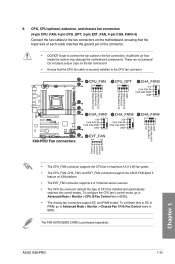
...installed and automatically switches the control modes. To set these fans to DC or PWM, go to the fan connectors. These are not jumpers! ASUS X99-PRO 1-33 CPU, CPU optional, extension, and chassis fan connectors (4-pin CPU_FAN; 4-pin CPU_OPT; 5-pin EXT_FAN, 4-pin CHA_FAN1-4) Connect the ...The CPU_FAN connector supports the CPU fan of maximum 1A (12 W) fan power. • The CPU_FAN, CHA_FAN, and EXT_FAN connectors support the ASUS FAN Xpert 3 feature on the motherboard, ensuring that the CPU fan cable is purchased separately. The FAN EXTENSION CARD is securely installed to Advanced...
...installed and automatically switches the control modes. To set these fans to DC or PWM, go to the fan connectors. These are not jumpers! ASUS X99-PRO 1-33 CPU, CPU optional, extension, and chassis fan connectors (4-pin CPU_FAN; 4-pin CPU_OPT; 5-pin EXT_FAN, 4-pin CHA_FAN1-4) Connect the ...The CPU_FAN connector supports the CPU fan of maximum 1A (12 W) fan power. • The CPU_FAN, CHA_FAN, and EXT_FAN connectors support the ASUS FAN Xpert 3 feature on the motherboard, ensuring that the CPU fan cable is purchased separately. The FAN EXTENSION CARD is securely installed to Advanced...

User Guide
Page 51
... puts the system in sleep mode. • Hard disk drive activity LED (2-pin HDD_LED) This 2-pin connector is for the chassis-mounted system warning speaker. ASUS X99-PRO 1-35 Chapter 1 8. The system power LED lights up or flashes when data is for the HDD Activity LED. The HDD LED lights up when you...
... puts the system in sleep mode. • Hard disk drive activity LED (2-pin HDD_LED) This 2-pin connector is for the chassis-mounted system warning speaker. ASUS X99-PRO 1-35 Chapter 1 8. The system power LED lights up or flashes when data is for the HDD Activity LED. The HDD LED lights up when you...
User Guide
Page 53
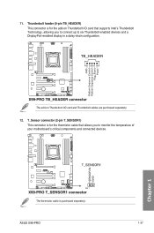
... is for the add-on Thunderbolt I /O card that allows you to connect up to monitor the temperature of your motherboard's critical components and connected devices. ASUS X99-PRO 1-37 Thunderbolt header (5-pin TB_HEADER) This connector is for the thermistor cable that supports Intel's Thunderbolt Technology, allowing you to six Thunderbolt-enabled devices and...
... is for the add-on Thunderbolt I /O card that allows you to connect up to monitor the temperature of your motherboard's critical components and connected devices. ASUS X99-PRO 1-37 Thunderbolt header (5-pin TB_HEADER) This connector is for the thermistor cable that supports Intel's Thunderbolt Technology, allowing you to six Thunderbolt-enabled devices and...
User Guide
Page 55
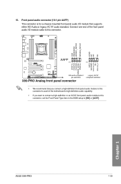
... a chassis-mounted front panel audio I /O module cable to this connector. • We recommend that supports either HD Audio or legacy AC`97 audio standard. Chapter 1 ASUS X99-PRO 1-39 15. Connect one end of the front panel audio I /O module that you connect a high-definition front panel audio module to this connector to avail...
... a chassis-mounted front panel audio I /O module cable to this connector. • We recommend that supports either HD Audio or legacy AC`97 audio standard. Chapter 1 ASUS X99-PRO 1-39 15. Connect one end of the front panel audio I /O module that you connect a high-definition front panel audio module to this connector to avail...


