
X99-E-10G WS User Guide for English.
Page 1
Motherboard X99-E-10G WS
Motherboard X99-E-10G WS
X99-E-10G WS User Guide for English.
Page 3
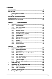
...X99-E-10G WS specifications summary x Package contents...xv Installation tools and components xvi Chapter 1: Product Introduction 1.1 Special features 1-1 1.1.1 Product highlights 1-1 1.1.2 Other special features 1-2 1.2 Motherboard overview 1-3 1.2.1 Before you proceed 1-3 1.2.2 Motherboard...16 1.2.8 Onboard LEDs 1-17 1.2.9 Internal connectors 1-24 Chapter 2: Basic Installation 2.1 Building your PC system 2-1 2.1.1 Motherboard installation 2-1 2.1.2 CPU installation 2-3 2.1.3 CPU heatsink and fan assembly installation 2-5 2.1.4 DIMM installation 2-6 2.1.5 ATX ...
...X99-E-10G WS specifications summary x Package contents...xv Installation tools and components xvi Chapter 1: Product Introduction 1.1 Special features 1-1 1.1.1 Product highlights 1-1 1.1.2 Other special features 1-2 1.2 Motherboard overview 1-3 1.2.1 Before you proceed 1-3 1.2.2 Motherboard...16 1.2.8 Onboard LEDs 1-17 1.2.9 Internal connectors 1-24 Chapter 2: Basic Installation 2.1 Building your PC system 2-1 2.1.1 Motherboard installation 2-1 2.1.2 CPU installation 2-3 2.1.3 CPU heatsink and fan assembly installation 2-5 2.1.4 DIMM installation 2-6 2.1.5 ATX ...
X99-E-10G WS User Guide for English.
Page 15
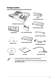
Actual product specifications may vary with different models. xv Package contents Check your motherboard package for the following items 10 x Serial ATA 6 Gb/s cables ASUS X99-E-10G WS motherboard 1 x 3-WAY SLI bridge connector 1 x ASUS Q-Shield 1 x 2-in-1 ASUS Q-Connector kit 1 x ASUS SLI® bridge connector COM port bracket 1 x 4-WAY SLI bridge connector 1 x RGB LED extension cable User Manual Support DVD User...
Actual product specifications may vary with different models. xv Package contents Check your motherboard package for the following items 10 x Serial ATA 6 Gb/s cables ASUS X99-E-10G WS motherboard 1 x 3-WAY SLI bridge connector 1 x ASUS Q-Shield 1 x 2-in-1 ASUS Q-Connector kit 1 x ASUS SLI® bridge connector COM port bracket 1 x 4-WAY SLI bridge connector 1 x RGB LED extension cable User Manual Support DVD User...
X99-E-10G WS User Guide for English.
Page 17
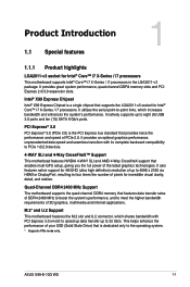
... bus standard that enables mulit-GPU setup, giving you the full power of 3D graphics, multimedia and Internet applications. Chapter 1 ASUS X99-E-10G WS 1-1 PCI Express® 3.0 PCI Express® 3.0 (PCIe 3.0) is dedicated only to meet the higher bandwidth requirements of... 1 1.1.1 Product highlights LGA2011-v3 socket for Intel® Core™ i7 X-Series / i7 processors. M.2* and U.2 Support This motherboard features the M.2 slot and U.2 connector, which increases bandwidth and enhances the system's performance. It provides great system performance, quad-channel DDR4...
... bus standard that enables mulit-GPU setup, giving you the full power of 3D graphics, multimedia and Internet applications. Chapter 1 ASUS X99-E-10G WS 1-1 PCI Express® 3.0 PCI Express® 3.0 (PCIe 3.0) is dedicated only to meet the higher bandwidth requirements of... 1 1.1.1 Product highlights LGA2011-v3 socket for Intel® Core™ i7 X-Series / i7 processors. M.2* and U.2 Support This motherboard features the M.2 slot and U.2 connector, which increases bandwidth and enhances the system's performance. It provides great system performance, quad-channel DDR4...
X99-E-10G WS User Guide for English.
Page 19
... avoid damaging them due to static electricity. • Hold components by the edges to the motherboard, peripherals, or components. Chapter 1 ASUS X99-E-10G WS 1-3 1.2 Motherboard overview 1.2.1 Before you proceed Take note of the following precautions before you install motherboard components or change any motherboard settings. • Unplug the power cord from the wall socket before touching any component...
... avoid damaging them due to static electricity. • Hold components by the edges to the motherboard, peripherals, or components. Chapter 1 ASUS X99-E-10G WS 1-3 1.2 Motherboard overview 1.2.1 Before you proceed Take note of the following precautions before you install motherboard components or change any motherboard settings. • Unplug the power cord from the wall socket before touching any component...
X99-E-10G WS User Guide for English.
Page 23
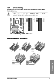
DO NOT install a DDR, DDR2, or DDR3 memory module to the DDR4 slot. Recommended memory configurations Chapter 1 ASUS X99-E-10G WS 1-7 A DDR4 module is notched differently from a DDR, DDR2, or DDR3 module. 1.2.4 System memory The motherboard comes with eight (8) DDR 4 (Double Data Rate 4) Quad Inline Memory Modules (DIMM) slots.
DO NOT install a DDR, DDR2, or DDR3 memory module to the DDR4 slot. Recommended memory configurations Chapter 1 ASUS X99-E-10G WS 1-7 A DDR4 module is notched differently from a DDR, DDR2, or DDR3 module. 1.2.4 System memory The motherboard comes with eight (8) DDR 4 (Double Data Rate 4) Quad Inline Memory Modules (DIMM) slots.
X99-E-10G WS User Guide for English.
Page 25
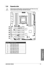
1.2.5 Expansion slots Unplug the power cord before adding or removing expansion cards. Chapter 1 Slot No. 1 2 3 4 5 6 7 Slot Description PCIe 3.0/2.0 x16_1 slot PCIe 3.0/2.0 x16_2 slot PCIe 3.0/2.0 x16_3 slot PCIe 3.0/2.0 x16_4 slot PCIe 3.0/2.0 x16_5 slot PCIe 3.0/2.0 x16_6 slot PCIe 3.0/2.0 x16_7 slot ASUS X99-E-10G WS 1-9 Failure to do so may cause you physical injury and damage motherboard components.
1.2.5 Expansion slots Unplug the power cord before adding or removing expansion cards. Chapter 1 Slot No. 1 2 3 4 5 6 7 Slot Description PCIe 3.0/2.0 x16_1 slot PCIe 3.0/2.0 x16_2 slot PCIe 3.0/2.0 x16_3 slot PCIe 3.0/2.0 x16_4 slot PCIe 3.0/2.0 x16_5 slot PCIe 3.0/2.0 x16_6 slot PCIe 3.0/2.0 x16_7 slot ASUS X99-E-10G WS 1-9 Failure to do so may cause you physical injury and damage motherboard components.
X99-E-10G WS User Guide for English.
Page 27
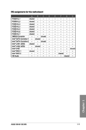
... Controller 2 - - PCIEX16_2 shared - - - Intel® LAN2 (x550) - shared - - - - - PCIEX16_3 PCIEX16_4 shared - - - Intel® SATA Controller 1 - Intel® EHCI 2 - - - - shared - - - - IRQ assignments for this motherboard A B C D PCIEX16_1 shared - - - shared - - shared - - - PCIEX16_6 shared - - - shared - Chapter 1 ASUS X99-E-10G WS 1-11 PCIEX16_7 shared - - - shared - shared - - Intel® LAN1 (x550) shared - - - Intel® xHCI - - - - Intel® EHCI 1 shared - - - HD Audio...
... Controller 2 - - PCIEX16_2 shared - - - Intel® LAN2 (x550) - shared - - - - - PCIEX16_3 PCIEX16_4 shared - - - Intel® SATA Controller 1 - Intel® EHCI 2 - - - - shared - - - - IRQ assignments for this motherboard A B C D PCIEX16_1 shared - - - shared - - shared - - - PCIEX16_6 shared - - - shared - Chapter 1 ASUS X99-E-10G WS 1-11 PCIEX16_7 shared - - - shared - shared - - Intel® LAN1 (x550) shared - - - Intel® xHCI - - - - Intel® EHCI 1 shared - - - HD Audio...
X99-E-10G WS User Guide for English.
Page 29
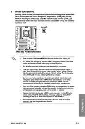
...to BIOS overclocking, press the MemOK! button to memory tuning requirement, the system automatically reboots when each timing set of failsafe settings. function. ASUS X99-E-10G WS 1-13 Chapter 1 The blinking speed of the DRAM_LED. • The DRAM_LED also lights up due to boot up when the DIMM is...recommended in the Memory QVL (Qualified Vendors Lists) at www.asus.com. • If you that the BIOS has been restored to test one set is not properly installed. Replace the DIMMs with the motherboard may cause system boot failure. button does not function under Windows...
...to BIOS overclocking, press the MemOK! button to memory tuning requirement, the system automatically reboots when each timing set of failsafe settings. function. ASUS X99-E-10G WS 1-13 Chapter 1 The blinking speed of the DRAM_LED. • The DRAM_LED also lights up due to boot up when the DIMM is...recommended in the Memory QVL (Qualified Vendors Lists) at www.asus.com. • If you that the BIOS has been restored to test one set is not properly installed. Replace the DIMMs with the motherboard may cause system boot failure. button does not function under Windows...
X99-E-10G WS User Guide for English.
Page 41
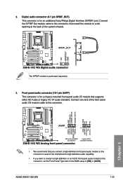
... a chassis-mounted front panel audio I /O module cable to this connector, then install the module to a slot opening at the back of the motherboard's high-definition audio capability. • If you want to connect a high-definition or an AC'97 front panel audio module to this connector, ...Audio or legacy AC`97 audio standard. Connect the S/PDIF Out module cable to [HD] or [AC97]. The S/PDIF module is purchased separately. 3. ASUS X99-E-10G WS 1-25 Chapter 1 Connect one end of the front panel audio I /O module that you connect a high-definition front panel audio module to this connector ...
... a chassis-mounted front panel audio I /O module cable to this connector, then install the module to a slot opening at the back of the motherboard's high-definition audio capability. • If you want to connect a high-definition or an AC'97 front panel audio module to this connector, ...Audio or legacy AC`97 audio standard. Connect the S/PDIF Out module cable to [HD] or [AC97]. The S/PDIF module is purchased separately. 3. ASUS X99-E-10G WS 1-25 Chapter 1 Connect one end of the front panel audio I /O module that you connect a high-definition front panel audio module to this connector ...

X99-E-10G WS User Guide for English.
Page 43
...and then install the Q-Connector (USB) to the USB connectors. USB 2.0 connectors (10-1 pin USB78, USB910) These connectors are for USB 2.0 ports. Chapter 1 ASUS X99-E-10G WS 1-27 DO NOT connect a 1394 cable to the USB connector onboard if your chassis supports front panel USB ports. 5. These USB connectors comply with USB... 2.0 specification that supports up to a slot opening at the back of the system chassis. Doing so will damage the motherboard! Connect the USB module cable to any of these connectors, then install the module to 48 Mb/s connection speed.
...and then install the Q-Connector (USB) to the USB connectors. USB 2.0 connectors (10-1 pin USB78, USB910) These connectors are for USB 2.0 ports. Chapter 1 ASUS X99-E-10G WS 1-27 DO NOT connect a 1394 cable to the USB connector onboard if your chassis supports front panel USB ports. 5. These USB connectors comply with USB... 2.0 specification that supports up to a slot opening at the back of the system chassis. Doing so will damage the motherboard! Connect the USB module cable to any of these connectors, then install the module to 48 Mb/s connection speed.

X99-E-10G WS User Guide for English.
Page 47
9. A TPM system also helps enhance network security, protect digital identities, and ensures platform integrity. Refer to this connector on the motherboard. DirectKey connector (2-pin DRCT) This connector is purchased separately. 10. ASUS X99-E-10G WS 1-31 The TPM module is for details. TPM connector (20-1 pin TPM) This connector supports a Trusted Platform Module (TPM) system, which...
9. A TPM system also helps enhance network security, protect digital identities, and ensures platform integrity. Refer to this connector on the motherboard. DirectKey connector (2-pin DRCT) This connector is purchased separately. 10. ASUS X99-E-10G WS 1-31 The TPM module is for details. TPM connector (20-1 pin TPM) This connector supports a Trusted Platform Module (TPM) system, which...

X99-E-10G WS User Guide for English.
Page 51
Chapter 1 ASUS X99-E-10G WS 1-35 T_Sensor connector (2-pin T_SENSOR1) This connector is purchased separately. 16. The thermistor cable is for the thermistor cable that allows you to monitor the temperature of your motherboard's critical components and connected devices.
Chapter 1 ASUS X99-E-10G WS 1-35 T_Sensor connector (2-pin T_SENSOR1) This connector is purchased separately. 16. The thermistor cable is for the thermistor cable that allows you to monitor the temperature of your motherboard's critical components and connected devices.

X99-E-10G WS User Guide for English.
Page 53
Place the motherboard into the chassis, ensuring that its rear I/O ports are aligned to the chassis rear I /O panel. Install the ASUS Q-Shield to the chassis' rear I /O panel. 2. Chapter 2 ASUS X99-E-10G WS 2-1 The motherboard layout may vary with models, but the installation steps are the same for reference only. Chapter 2: Basic Installation Basic Installation 2.1 Building your PC system 2 2.1.1 Motherboard installation The diagrams in this section are for all models. 1.
Place the motherboard into the chassis, ensuring that its rear I/O ports are aligned to the chassis rear I /O panel. Install the ASUS Q-Shield to the chassis' rear I /O panel. 2. Chapter 2 ASUS X99-E-10G WS 2-1 The motherboard layout may vary with models, but the installation steps are the same for reference only. Chapter 2: Basic Installation Basic Installation 2.1 Building your PC system 2 2.1.1 Motherboard installation The diagrams in this section are for all models. 1.
X99-E-10G WS User Guide for English.
Page 63
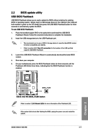
Place the bundled support DVD to boot after flashing the BIOS, unplug the power core and restart the system. Shut down your motherboard, press the BIOS Flashback button for the location of the Flashback LED. If the system fails to the optical drive and install the USB BIOS ... seconds to automatically update the BIOS. 2.2 BIOS update utility USB BIOS Flashback USB BIOS Flashback allows you to use USB BIOS Flashback: 1. On your computer. 5. ASUS X99-E-10G WS 2-11 Follow the onscreen instructions to automatically download the latest BIOS version. 4.
Place the bundled support DVD to boot after flashing the BIOS, unplug the power core and restart the system. Shut down your motherboard, press the BIOS Flashback button for the location of the Flashback LED. If the system fails to the optical drive and install the USB BIOS ... seconds to automatically update the BIOS. 2.2 BIOS update utility USB BIOS Flashback USB BIOS Flashback allows you to use USB BIOS Flashback: 1. On your computer. 5. ASUS X99-E-10G WS 2-11 Follow the onscreen instructions to automatically download the latest BIOS version. 4.
X99-E-10G WS User Guide for English.
Page 65
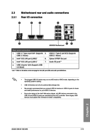
...USB devices must update their firmware for your USB 3.0 devices. • Due to the design of the Intel® X99 series chipset, all USB devices connected to the USB 2.0 and USB 3.0 ports are controlled by the xHCI controller. USB... better performance for better compatibility. Chapter 2 ASUS X99-E-10G WS 2-13 Intel® 10G LAN port (LAN1)* 7. USB 3.1 Type-C port EC2 (Supports USB 3.1 Boost) USB 3.1 Boost) 2. Intel® 10G LAN port (LAN2)* 6. Audio I /O connection USB BIOS Flashback port Rear panel connectors 1. 2.3 Motherboard rear and audio connections 2.3.1 Rear I /O...
...USB devices must update their firmware for your USB 3.0 devices. • Due to the design of the Intel® X99 series chipset, all USB devices connected to the USB 2.0 and USB 3.0 ports are controlled by the xHCI controller. USB... better performance for better compatibility. Chapter 2 ASUS X99-E-10G WS 2-13 Intel® 10G LAN port (LAN1)* 7. USB 3.1 Type-C port EC2 (Supports USB 3.1 Boost) USB 3.1 Boost) 2. Intel® 10G LAN port (LAN2)* 6. Audio I /O connection USB BIOS Flashback port Rear panel connectors 1. 2.3 Motherboard rear and audio connections 2.3.1 Rear I /O...

X99-E-10G WS User Guide for English.
Page 71
... storage device configuration, overclocking settings, advanced power management, and boot device configuration that requires further BIOS settings or update. Chapter 3 ASUS X99-E-10G WS 3-1 Inappropriate BIOS settings may result to ensure optimal performance. When downloading or updating the BIOS file, rename it as your operating ...system. You can easily navigate the new UEFI BIOS with the same smoothness as X99E10G.CAP for system startup in this motherboard. DO NOT change the BIOS settings only with the help of a trained service personnel. Chapter 3: BIOS Setup BIOS Setup 3.1 ...
... storage device configuration, overclocking settings, advanced power management, and boot device configuration that requires further BIOS settings or update. Chapter 3 ASUS X99-E-10G WS 3-1 Inappropriate BIOS settings may result to ensure optimal performance. When downloading or updating the BIOS file, rename it as your operating ...system. You can easily navigate the new UEFI BIOS with the same smoothness as X99E10G.CAP for system startup in this motherboard. DO NOT change the BIOS settings only with the help of a trained service personnel. Chapter 3: BIOS Setup BIOS Setup 3.1 ...
X99-E-10G WS User Guide for English.
Page 73
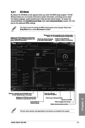
...Creates storage RAID and of the selected mode. 3.2.1 EZ Mode By default, the EZ Mode screen appears when you enter the BIOS setup program. ASUS X99-E-10G WS 3-3 Click < or > to the Setup Mode item in section Boot menu for Intel Rapid Storage Technology Displays the CPU Fan's speed. To...press hot key for entering the BIOS setup program can be changed. The default screen for the advanced BIOS settings. Displays the CPU/motherboard temperature, CPU voltage output, CPU/chassis/power fan speed, and SATA information Displays the system properties of the BIOS setup program configures ...
...Creates storage RAID and of the selected mode. 3.2.1 EZ Mode By default, the EZ Mode screen appears when you enter the BIOS setup program. ASUS X99-E-10G WS 3-3 Click < or > to the Setup Mode item in section Boot menu for Intel Rapid Storage Technology Displays the CPU Fan's speed. To...press hot key for entering the BIOS setup program can be changed. The default screen for the advanced BIOS settings. Displays the CPU/motherboard temperature, CPU voltage output, CPU/chassis/power fan speed, and SATA information Displays the system properties of the BIOS setup program configures ...

X99-E-10G WS User Guide for English.
Page 75
... can select for your BIOS screen. It also allows you to section 3.3 My Favorites for that the item has a submenu. Chapter 3 ASUS X99-E-10G WS 3-5 Boot Tool Exit For changing the system boot configuration For configuring options for special functions For selecting the exit options and loading default settings... bar The menu bar on any menu screen means that menu. Language This button above the menu bar allows you to change the motherboard's SATA mode from AHCI to section 3.2.3 QFan Control for more information. Refer to RAID mode. Click this button to manually tweak the...
... can select for your BIOS screen. It also allows you to section 3.3 My Favorites for that the item has a submenu. Chapter 3 ASUS X99-E-10G WS 3-5 Boot Tool Exit For changing the system boot configuration For configuring options for special functions For selecting the exit options and loading default settings... bar The menu bar on any menu screen means that menu. Language This button above the menu bar allows you to change the motherboard's SATA mode from AHCI to section 3.2.3 QFan Control for more information. Refer to RAID mode. Click this button to manually tweak the...
X99-E-10G WS User Guide for English.
Page 115
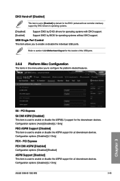
... host controller interface) support by EHCI drivers in this menu allow you to enable or disable the individual USB ports. Chapter 3 SA - Refer to section 1.2.2 Motherboard layout for the location of the USB ports. 3.6.6 Platform Misc Configuration The items in operating systems. [Disabled] [Enabled] Support EHCI by EHCI drivers for operating...
... host controller interface) support by EHCI drivers in this menu allow you to enable or disable the individual USB ports. Chapter 3 SA - Refer to section 1.2.2 Motherboard layout for the location of the USB ports. 3.6.6 Platform Misc Configuration The items in operating systems. [Disabled] [Enabled] Support EHCI by EHCI drivers for operating...


